
Related Manuals for Beckhoff CX1000-0 SERIES


Summary of Contents for Beckhoff CX1000-0 SERIES
- Page 1 CX1000 Embedded PC Hardware documentation CX1000-0xxx CX1000-Nxxx version: 1.1 date: 2006-06-21...
-
Page 3: Table Of Contents
Table of contents Table of contents CX1000 Hardware Documentation 1. Foreword Notes on the Manual Safety instructions Documentation Issue Status 2. Product Overview Appropriate Use System Overview Base Modules Technical Data Types Connections Compact flash insert Compact flash card PC 104 bus System interfaces Technical Data Connections CX1000-N001... - Page 4 Table of contents Power supplys LED CX1100-0001 LED CX1100-0002 LED CX1100-0003 Trouble shooting 6. Decommissioning Removal and disposal 7. Appendix Accessories Support Certificates Embedded PC...
-
Page 5: Foreword
© This manual is copyrighted. Any reproduction or third party use of this publication, whether in whole or in part, without the written permission of Beckhoff Automation GmbH, is forbidden. Associated publication For commissioning the use of the appropriate hardware documentation is recommended apart from this documentation. -
Page 6: Safety Instructions
All the components are supplied in particular hardware and software configurations appropriate for the application. Modifications to hardware or software configurations other than those described in the documentation are not permitted, and nullify the liability of Beckhoff Automation GmbH. Personnel Qualification This description is only intended for the use of trained specialists in control and automation engineering who are familiar with the applicable national standards. -
Page 7: Documentation Issue Status
Foreword Documentation Issue Status Version Changes comments on hardware watchdog added updated version preliminarily version Embedded PC... -
Page 8: Product Overview
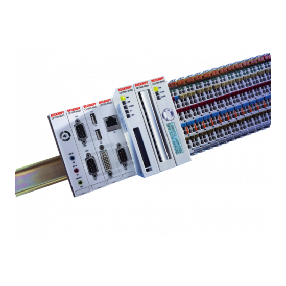
Product Overview 2. Product Overview Appropriate Use The CX1000 device series is a modular control system that can be mounted on top hat rails. Its components are plugged together and installed in the control cabinet or junction box, depending on the required function. Embedded PC... -
Page 9: System Overview
Ethernet and RS 232 interfaces. If local visualisation is required, this can be implemented via a DVI (digital video interface), to which all Beckhoff Control Panels and all commercially available monitors with DVI-input can be connected. The touch screen signal is read via one of the two available USB interfaces. - Page 10 (master and slave) und SERCOS Interface (only master). The use of fieldbus master modules in a CX1000 system enables the utilisation of all Beckhoff fieldbus components (e. g. Bus Coupler, Bus Terminal Controller, drive technology) as distributed control components for the assembly of...
-
Page 11: Base Modules
The passive cooling module CX1000-COOL is included in the scope of supply. Note The Watchdog function is only supported by Beckhoff in combination of TwinCAT with WINDOWS NT based systems. For other operating systems without TwinCAT it is not possible to give a general solution. -
Page 12: Types
Product Overview Types The CPU module can be equipped with different hardware and software options: the internal memory is expandable to 32 MB Flash/128 MB RAM; the operating systems can be Windows CE.NET or Windows XP Embedded. The TwinCAT automation software transforms a CX1000 system into powerful PLC and Motion Control system that can be operated with or without visualisation. - Page 13 Product Overview CX1001- 0112 CX1001- 0120 CX1001- 0121 CX1001- 0122 CX1000 systems with Windows XP Embedded require a Compact Flash card with a minimum capacity of 128 MB. Note: A list of the different software images can be found in the CX1000 Software Documentation. Embedded PC...
-
Page 14: Connections
Product Overview Connections The basic CPU module is available with different hardware and software options. It is supplied from the power supply unit, so that only the connections are described here. Basic CPU module with Ethernet RJ 45 and COM1 (RS232) interface: RJ 45 interface (socket): Assignment of the RJ45 interface: Signal... - Page 15 Product Overview Basic CPU module with DVI/USB interface: In addition to the Ethernet and COM interface, this basic module features a DVI-I and two USB interfaces. The pin assignment of the basic CPU module with two USB and a DVI-I interface is explained under the associated system interface CX1000-N001.
-
Page 16: Compact Flash Insert
Warning It is recommended only use CF cards supplied by Beckhoff Automation GmbH. The CF cards are made for industrial use. They possess a higher number of read / write cycles and an enhance temperature range (up to + 85°C). -
Page 17: Pc 104 Bus
Product Overview PC 104 Bus The PC 104 bus is a standerdised bus with 104ISA signals for compact embedded systems. For the functionality of the CX1000 modules eight further signals have been added ( here marked with color). Pin assignment of 16 bit PC 104 bus: J1/P1 J1/P1 J1/P1... - Page 18 Product Overview Remarks: 2. B10 and C19 are key locations. 3. Signal timing and function are as specified in ISA specification. 4. Signal source/sink current differ from ISA values. Pin assignment of the addtional signals Pin number Assignment I²C SCL USB D+ I²C SDA USB D-...
-
Page 19: System Interfaces
Product Overview System interfaces Technical Data Unlike other CX components, the system interfaces cannot be upgraded or expanded in the field. They are supplied ex factory in the specified configuration and cannot be separated from the CPU module. The system interfaces run through the internal PC104, so that further CX components can be connected. -
Page 20: Connections Cx1000-N001
The DVI-I interface transfers analog and digital data and is suitable for connection to analog graphics cards with 15 pin D-Sub connector and digital graphics cards with DVI-D output. The resolution at the screen or the Beckhoff Control Panel depends on the distance (maximum 7 m). - Page 21 Product Overview USB interface: The USB socket is a type A socket. The USB interface complies to USB 1.1 specification Assignment Typical assignment VBUS White Green Black Shell Shield Drain Wire Embedded PC...
-
Page 22: Connections Cx1000-N002
Product Overview CX1000-N002 connections The CX1000-N002 system interface features two RS232 interfaces, COM2 and COM3 (9 pin Sub-D plug connector). The maximum baud rate on both channels is 115 kBit. RS232 COM interface (connector): Pin assignment of the COM2 interface: Signal Type Description... -
Page 23: Connections Cx1000-N003
Product Overview CX1000-N003 connections This system interface contains the audio interfaces Line In, Mic In (microphone signal input) and Line Out (also for earphones), max. 200 mW. It also features a PC beeper. The 3.5 mm sockets are designed for jack plugs. Line In / Line Out stereo jack plugs: Pin assignment Line In /Line Out: Signal... -
Page 24: Connections Cx1000-N005
Product Overview CX1000-N005 connections The system interface CX1000-N005 contains two RS422, RS485 interfaces, COM2 and COM3 (9 pin Sub-D plug connector). The maximum baud rate on both channels is 115 kBit. COM interface (plug): Pin assignment of the COM interface: Signal Type Description... - Page 25 Product Overview RS485 without Echo, Drop-Point ( without Termination) Status Function Echo on Echo off Auto send on Always send on Auto receive on Always receive on Term on Term on RS485 with Echo, Drop-Point ( without Termination) Status Function Echo on Echo off Auto send on...
-
Page 26: Power Supply
Product Overview Power supply Technical Data CX1100-0001 One of three power supply modules can be selected for a CX1000 system. The power supply of all other system components is ensured via the internal PC104 bus; no separate supply lines are required. However, the CX1100 components offer further important characteristics that go beyond a pure power supply: an integrated NOVRAM enables the fail-safe storage of process data, an LCD display with two lines of 16 characters each is used for displaying system and user messages. -
Page 27: Technical Data Cx1100-0002 / Cx1100-0003
Technical Data CX1100-0002 / CX1100-0003 Local I/O signals are connected via the CX1100-0002 power supply variant, to which all Beckhoff Bus Terminals can be connected, or via CX1100-0003, which in addition to the Bus Terminals enables the connection of Extension Box IExxxx type Beckhoff Fieldbus Box modules. -
Page 28: Connections Cx1100-0001
Product Overview CX1100-0001 Connections This power supply unit does not have an I/O interface. The power supply is therefore connected through the 5-pin open pluggable connector. The power supply unit supplies all further system components with a voltage of 24 V DC (- 15 %/+20%) via the PC104 bus. -
Page 29: Connections Cx1100-0002
Product Overview CX1100-0002 Connections This power supply unit is equipped with an I/O interface, which permits connection of the Beckhoff Bus Terminals. The power is supplied via the upper spring-loaded terminals labelled “24V” and “0V”. The supply voltage feeds the CX system and supplies a voltage of 24 V DC (-15 %/+20%) to the Bus Terminals via the K-Bus. -
Page 30: Connections Cx1100-0003
This power supply unit permits not only the connection of the Beckhoff Bus Terminals, but also the serial connection of the Beckhoff fieldbus box modules of the type extension box IExxxx. The power is supplied via the upper spring- loaded terminals labelled “24V” and “0V”. -
Page 31: Lcd Display
Product Overview LCD Display The LCD display of the power supply units has two rows of 16 characters each and is used for displaying system and user messages. "Index-Group/Offset" Specification for the LCD Display ADS Port 300 Index Data Phys. Def. -
Page 32: Transport
4. Please keep the associated paperwork. It contains important information for handling the unit. 5. Check the contents for visible shipping damage. 6. If you notice any shipping damage or inconsistencies between the contents and your order, you should notify Beckhoff Service. Warning Danger of damage to the unit! During transport in cold conditions, or if the unit is subjected to extreme temperature swings, condensation on and inside the unit must be avoided. -
Page 33: Fitting And Wiring
The overall width of the application is made up of the individual modules. With a height of 100 mm, the module dimensions exactly match those of the Beckhoff Bus Terminals. Together with the lowered connector surfaces, this means that it can be used in a standard terminal box with a height of 120 mm. -
Page 34: Mechanical Assembly Of The Base Module
Fitting and wiring Mechanical Assembly of the base module The installation of the modules takes place in three steps: 1. The Sequence of the Modules The CPU basic module with system interfaces, which are factory-installed on the left side, is extended with the power supply unit on the right and with the fieldbus connection (master or slave) left side if available. - Page 35 Fitting and wiring FIG. 6: Tension straps back in starting position FIG.7: Tension straps not engaged / engaged Note: A locking mechanism prevents the individual housings from being pulled off again. More detailed information about disassembling the CX configuration from the top-hat rail can be found on the page decommissioning. By lowering the front surfaces, which contain the interfaces, installation can easily be done in a standard terminal box of 120 mm height.
- Page 36 Fitting and wiring FIG. 9: Allowable installation position FIG. 10: Unallowable installation position Embedded PC...
-
Page 37: Mechanical Mounting Of The Fieldbus Modules
Fitting and wiring Mechanical mounting of the Fieldbus modules The mounting of the Fieldbus modules takes place in several steps: 1. Remove cover at CX1000/CX1020 basic module In order to be able to fasten the connection of the fieldbus connection to the CPU basic module, the cover must first be removed (FIG 1, 2). - Page 38 Fitting and wiring FIG. 4: Tension straps back in starting position 3. Attach Cover If the connection area does not have a closing cover on the left-hand side, the cover that was previously removed should be pressed over the connections until it audibly engages. Note: If the CX1000/CX1020 configuration is not positioned on the top-hat rail it is possible to join the connection first with the CX1000/CX1020 configuration, as shown in FIG.
-
Page 39: Error Handling And Diagnostics
Error handling and diagnostics 5. Error handling and diagnostics CPU base module LEDs of the basic CPU module Display Meaning Power supply The Power LED comes on when the device is connected to a live power supply unit. Link LAN Link 10 MBit This LED comes on when the network speed is 10 MBit or 100 MBit (if the device is part of a network). -
Page 40: Power Supplys
Error handling and diagnostics Power supplys CX1100-0001 power supply LEDs Display Meaning Power Power supply The LED lights up green when the power supply is correct, but red if there is a short circuit. Embedded PC... -
Page 41: Led Cx1100-0002
Error handling and diagnostics CX1100-0002 power supply LEDs After switching on, the power supply immediately checks the connected Bus Terminal configuration. Error-free start- up is signalled by the red "I/O ERR” LED being extinguished. If the ”I/O ERR" LED blinks, an error in the area of the terminals is indicated. - Page 42 Error handling and diagnostics consistent with the clear the boot project. configuration that existed when the boot project was created 14 pulses nth Bus Terminal has the Start the power supply again, and if the error wrong format occurs again then exchange the Bus Terminal.
-
Page 43: Led Cx1100-0003
Error handling and diagnostics CX1100-0003 power supply LEDs After switching on, the power supply immediately checks the connected Bus Terminal configuration. Error-free start- up is signalled by the red "I/O ERR” LED being extinguished. If the ”I/O ERR" LED blinks, an error in the area of the terminals is indicated. - Page 44 Error handling and diagnostics consistent with the clear the boot project. configuration that existed when the boot project was created 14 pulses nth Bus Terminal has the Start the power supply again, and if the error wrong format occurs again then exchange the Bus Terminal.
-
Page 45: Trouble Shooting
Error handling and diagnostics Störungen Lesen Sie dazu auch das Kapitel Sicherheitshinweise. Mögliche Störungen und ihre Beseitigung Bitte geben Sie im Servicefall die Projektnummer Ihres PCs an, welche Sie dem Typenschild entnehmen können. Die BECKHOFF-Support Nummer: für Deutschland: 05246/963-157 international: +49-5246/963-157 Störung Ursache Maßnahmen... -
Page 46: Decommissioning
Decommissioning 6. Decommissioning Removal and disposal A CX1000 hardware configuration is dismantled in 2 stages: 1. Removing from the top-hat rail: The white straps on the underneath of all the modules must be pulled downwards (FIG 1). This can be done using an ordinary screwdriver and a slight turn. - Page 47 Decommissioning FIG. 4: Undoing the latching mechanism FIG 5: Separating the modules The CPU can be separated from the power supply unit and the fieldbus connections in this way. Note: If the configuration has a power supply unit with an I/O interface, it is first necessary to release one terminal from the top-hat rail so that the configuration can be separated from the I/O hardware.
-
Page 48: Appendix
Appendix 7. Appendix Accessories Compact flash cards order number Description CX1900-0015 128 MByte compact flash card type I CX1900-0017 256 MByte compact flash card type I CX1900-0021 512 MByte compact flash card type I CX1900-0023 1 GByte compact flash card type I CX1900-0025 2 GByte compact flash card type I CX1900-0027... -
Page 49: Support
33415 Verl Germany Phone: +49(0)5246/963-0 Fax: +49(0)5246/963-198 e-mail: info@beckhoff.com The addresses of Beckhoff's branch offices and representatives round the world can be found on her internet pages: http://www.beckhoff.com You will also find further documentation for Beckhoff components there. Embedded PC... -
Page 50: Certificates
All products of the Embedded PC family are CE, UL and GOST-R certified. Since the product family is continuously developed further, we are unable to provide a full listing here. The current list of certified products can be found on the Embedded PC certificates web page or at www.beckhoff.de under Embedded PC. Embedded PC...
Need help?
Do you have a question about the CX1000-0 SERIES and is the answer not in the manual?
Questions and answers