Table of Contents
Advertisement
Advertisement
Table of Contents

Related Manuals for MKN FlexiCombi MagicPilot Series


Summary of Contents for MKN FlexiCombi MagicPilot Series
-
Page 1: Installation Instructions
Read the operating instructions prior to commissioning Installation instructions Combisteamer Unit Type of energy Unit type Model FlexiCombi MagicPilot Electric Countertop unit FKECOD615 FKECOD621 FKECOD115 FKECOD121 Floor-standing unit FKECOD215 FKECOD221 10013865-0AIBE-B en-GB... - Page 2 Fax +49 5331 89-280 Internet www.mkn.eu Copyright All rights to text, graphics and pictures in this documentation are held by MKN Maschinenfabrik Kurt Neubauer GmbH & Co. KG. Distribution or duplication is only permitted with the prior written consent of MKN.
-
Page 3: Table Of Contents
Directory of contents 1 Introduction ................. 5 1.1 About this manual ................ 5 1.1.1 Explanation of signs .................. 6 1.2 Use of the unit ................... 7 1.3 Warranty .................... 7 2 Safety information .............. 8 3 Description of the unit ............. 10 3.1 Overview of the unit ............... 10 3.2 Planning drawing ................ ... - Page 4 Directory of contents 7 Testing the function ............ 41 7.1 Checking the controls .............. 41 7.2 Checking the monitoring of the cooking zone door .... 42 7.3 Running the self-diagnosis ............ 42 8 Putting the unit into service .......... 43 8.1 Filling out the Commissioning report ........... 43 Installation instructions...
-
Page 5: 1 Introduction
Introduction 1 Introduction 1.1 About this manual The instruction manual is part of the unit and contains information on safe installation of the unit. Observe and adhere to the following instructions: • Read the instruction manual in its entirety prior to installation. •... -
Page 6: Explanation Of Signs
Introduction 1.1.1 Explanation of signs DANGER Imminent threat of danger Failure to comply will lead to death or very severe injuries. WARNING Possible threat of danger Failure to comply can lead to death or very severe injuries. CAUTION Dangerous situation Failure to comply can lead to slight or moderately severe injuries. -
Page 7: Use Of The Unit
Introduction 1.2 Use of the unit This unit is intended to be used solely for commercial purposes, particularly in commercial kitchens. The use of the unit is prohibited in the following countries: • • Canada 1.3 Warranty The warranty is void and safety is no longer assured in the event of: •... -
Page 8: 2 Safety Information
Safety information 2 Safety information The unit complies with applicable safety standards. Residual risks associated with operation or risks resulting from incorrect operation cannot be ruled out and are mentioned specifically in the safety instructions and warnings. The installer must be familiar with regional regulations and observe them. - Page 9 Safety information Setup Risk of property damage and personal injury from improper setup • Ensure that the installation area has adequate load-bearing capacity. • Wear safety shoes and protective gloves. Electrical connection Risk of fire from improper connection • Observe applicable regional regulations of the electrical utility. •...
-
Page 10: 3 Description Of The Unit
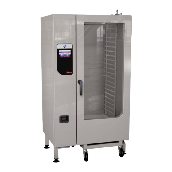
Description of the unit 3 Description of the unit 3.1 Overview of the unit Image: Unit with tray rack trolley a Tray rack k Nameplate b Insulated window l Base frame (optional) c Door handle m Equipment leg d Cooking zone door n Control unit e Tray rack trolley (optional) o Housing... - Page 11 Description of the unit Image: Unit with tray trolley a Tray rack j Hand shower b Insulated window k Nameplate c Door handle l Equipment leg d Cooking zone door m Control unit e Guide rail (right) n Housing f Tray trolley o Air inlet g Push handle p Steam outlet...
-
Page 12: Planning Drawing
Description of the unit 3.2 Planning drawing Image: Size 6XX and 1XX Image: Size 2XX Size 615, 621 115, 121 215, 221 1075 1060 1640 1640 1960 All dimensions in mm Installation instructions... -
Page 13: Equipment And Connection Data
Description of the unit 3.3 Equipment and connection data Model: FKECOD Size Dimensions Unit 997 x 799 x 790 997 x 799 x 1060 1075 x 813 x 1960 Length x Width x Height (mm) Weight (kg) unit Emissions Latent heat (W) 1780* 3670* 2750*... - Page 14 Description of the unit Model: FKECOD Size Voltage (V) Connected load (kW) 10.4 20.9 15.9 30.5 31.7 60.9 Fuse (A) 3 x 16 3 x 35 3 x 25 3 x 50 3 x 50 3 x 100 Voltage (V) Connected load (kW) 11.2 22.5...
- Page 15 Description of the unit Model: FKECOD Size Temperature resistance (°C) Maximum flow rate (l/min) Exhaust air connection Connection to unit (mm) Maximum length (m) Temperature resistance (°C) Transformer voltage Type of connection 3NPE / AC 50/60 Hz Voltage range (V) 200 — 240 Transformer Marking or colour of the cores Blue...
- Page 16 Description of the unit Basic control setting Basic setting Parameter Standard Adjustment Explanation value range Date / time yyyy - mm - dd Year - Month - Day hh : mm Hour : Minute Unit of temperature °C °C Celsius (°C) °F Fahrenheit (°F) Altitude...
- Page 17 Description of the unit Basic control setting (Advanced) Basic setting Parameter Standard Adjustment Explanation value range Ready2Cook 0 — 30 % If the unit is fully loaded with a large mass preheating (roasts, loaves of bread), increase the temperature preheat temperature so that the cooking zone temperature does not drop too suddenly.
-
Page 18: 4 Transporting The Unit
Transporting the unit 4 Transporting the unit CAUTION Risk of property damage and personnel injury from tipping equipment • Do not linger next to or behind raised equipment. • Move raised equipment carefully. ATTENTION Risk of physical damage from improper transport •... -
Page 19: Unpacking The Unit
Transporting the unit 4.2 Unpacking the unit CAUTION Risk of injury from sharp edges • Wear protective gloves. When unpacking the unit, inspect it for transport damage. Do not install damaged units or put into service. 1. Remove the packaging. 2. -
Page 20: 5 Setting Up The Unit
Setting up the unit 5 Setting up the unit WARNING Risk of burns from spraying hot fat • Set up deep fat fryers outside the range of the hand shower. CAUTION Risk of crushing from improper setup • Protect the unit and work area during setup and alignment. CAUTION Risk of fire from failure to observe applicable regional fire prevention regulations... -
Page 21: Maintaining Minimum Clearances
Setting up the unit 5.1 Maintaining minimum clearances Image: Minimum clearances to walls, ceiling or units All dimensions in mm * Recommended for service work 500 mm The following clearances from walls, ceilings or other equipment must be maintained when setting up the unit: •... -
Page 22: Lifting The Unit Off The Pallet
Setting up the unit 5.2 Lifting the unit off the pallet CAUTION Risk of property damage and personnel injury from tipping equipment • Do not linger next to or behind raised equipment. • Move raised equipment carefully. ATTENTION Risk of physical damage from lifting the unit incorrectly •... -
Page 23: Setting Up The Unit On A Base Frame
Setting up the unit 5.4 Setting up the unit on a base frame Image: Setting up the unit on a base frame a Lifting fork d Stud bolt b Waste trap on the unit e Equipment leg c Base frame f Unit Requirement The base frame must carry the weight of the unit Base frame levelled... -
Page 24: Installing The Support Rack
Setting up the unit 5.4.1 Installing the support rack Depending on the version, the base frame can be equipped with a support rack. The support rack is used to hold containers, metal trays and grates. Image: A Stop profile, B Support rack a Stop profile c Outboard support rack b Pin... - Page 25 Setting up the unit 3. Open the cooking zone door. 4. Move the tray trolley into the unit until it stops and check the alignment. 5. Close the cooking zone door. The sheet metal seal on the tray trolley should make full contact (no gaps) with the door seal.
-
Page 26: 6 Connecting The Unit
Connecting the unit 6 Connecting the unit DANGER Risk of personal injury and physical damage from electric shock • Prior to working on the unit, ensure that the unit has been disconnected from the mains. • Do not operate the unit with the housing open. CAUTION Risk of injury from sharp edges •... -
Page 27: Making The Power Connection
Connecting the unit Attaching side wall ATTENTION Risk of physical damage from leaky housing • Check seals when attaching the housing parts. • Replace damaged gaskets. 1. Insert the top edge of the side wall. 2. Carefully push the bottom of the side wall inwards. 3. - Page 28 Connecting the unit Permanent connection CAUTION Risk of property damage and personal injury from improper installation • In the case of a permanent electrical connection, install an all-phase disconnect switch before the unit. Install an all-phase disconnect switch if the unit will be connected permanently to the electric mains.
-
Page 29: Matching The Unit To The Connection Voltage
Connecting the unit Equipotential bonding Image: Equipotential bonding symbol The unit must be included in a potential equalisation system by means of appropriately sized wiring. 6.2.1 Matching the unit to the connection voltage DANGER Risk of personal injury and physical damage from electric shock •... - Page 30 Connecting the unit Image: A Transformer position T1; B Connection for transformer controls Image: A Transformer position T0, only for unit without neutral wire; B Transformer connection Requirement Unit not live Left side wall removed 1. Measure the connection voltage with a suitable measuring device. The voltage range must match that on the nameplate.
-
Page 31: Connecting The Power Connection Cable
Connecting the unit 6.2.2 Connecting the power connection cable DANGER Risk of personal injury and physical damage from electric shock • Prior to working on the unit, ensure that the unit has been disconnected from the mains. • Do not operate the unit with the housing open. DANGER Risk of personal injury and physical damage from electric shock... -
Page 32: Connecting The Power Optimisation System
Connecting the unit Requirement Unit not live Power connection cable not live Unit matched to the connection voltage Side wall open 1. Route the power connection cable into the unit through the cable gland. 2. Connect the power connection cable in accordance with the wiring diagram. -
Page 33: Connecting To The Potential Equalisation Circuit
Connecting the unit 6.2.4 Connecting to the potential equalisation circuit Image: Connecting the potential equalisation circuit 1. Run and attach potential equalisation line to the identified terminal. 2. Fill out the commissioning report. 6.3 Connecting the kitchen management system The units can be connected with a RJ45 plug to a kitchen management system. - Page 34 Connecting the unit Minimum requirements for the network cable Type of network Ethernet Cable quality 4-pair, shrouded patch cable Cat-6 S/FTP Connection to unit Shrouded RJ45 plug Image: Connecting the kitchen management system a RJ45 socket d Cable tie b RJ45 plug e Ferrite ring c Network cable Requirement Unit not live...
-
Page 35: Making The Basic Control Setting
Connecting the unit 6.4 Making the basic control setting Image: Main menu a Main menu d "Equipment functions" button b FlexiHelp button e Back button c Language selection 6.4.1 Changing the basic control setting By entering the password "2100", the basic settings for the installation can be displayed and changed. -
Page 36: Making The Water Connection
Connecting the unit 6.5 Making the water connection Installation work involving drinking water must be performed by an authorised plumbing contractor. Observe applicable regional regulations with regard to drinking water installations and connection data (see "Equipment and connection data"). The unit has a connection for permanent attachment the drinking water system. -
Page 37: Connecting The Tap Water Connection Line
Connecting the unit 6.5.1 Connecting the tap water connection line Image: Water connection a Soft water d Tap water connection b Backflow preventer e Tap water connection line c Soft water connection f Tap water Requirement Water pressure complies with the specified range (see "Equipment and connection data") Backflow preventer installed The connection lines are pressure-tight and suitable for tap water... -
Page 38: Connecting Softened Tap Water To Both Connections
Connecting the unit 6.5.2 Connecting softened tap water to both connections If only softened tap water is available at the installation site, use a T- piece to connect both water connections on the unit to each other. Image: Connecting softened tap water to both connections a Softened tap water e Tap water connection b Backflow preventer... -
Page 39: Making The Wastewater Connection
Connecting the unit 6.6 Making the wastewater connection Installation work involving wastewater must be performed by an authorised plumbing contractor. Observe the applicable regional regulations of the sewage utility involved. 6.6.1 Connecting the wastewater line to a permanent connection Image: Wastewater line to a permanent connection a Wastewater connection d Sewer system waste trap b Wastewater line... -
Page 40: Making The Exhaust Air Connection
Connecting the unit 6.7 Making the exhaust air connection When setting up the unit under a ventilation system, observe the regional regulations for heating, ventilation and air conditioning systems. ATTENTION Risk of physical damage from fouling of the exhaust air ducts •... -
Page 41: 7 Testing The Function
Testing the function 7 Testing the function DANGER Risk of personal injury and physical damage from unsuccessful operational check • Do not put the unit into service. • Contact customer service. Requirement Power connection made Water connection made Wastewater connection made Unit cleaned 7.1 Checking the controls 1. -
Page 42: Checking The Monitoring Of The Cooking Zone Door
Testing the function 7.2 Checking the monitoring of the cooking zone door 1. Switch on the unit and start any cooking program (see operating instructions). The unit starts to heat. The fan wheel is turning. 2. Open the cooking zone door during operation. The unit shuts off the heating function. -
Page 43: 8 Putting The Unit Into Service
Putting the unit into service 8 Putting the unit into service If the unit is not put into service immediately after being connected and the function check, all inspections must be repeated. Requirement Power connection made Water connection established Wastewater connection established Exhaust connection made ... - Page 44 Putting the unit into service Basic control setting Unit of temperature set? °C °F Have date and time been set? Has software version been identified? Version: __________ Altitude set? 0 — 999 m 1000 m — 1999 m 2000 m — 2499 m 2500 m or higher 80 % power set? 100 % 80 %...
- Page 45 Putting the unit into service Wastewater connection Wastewater connection made properly? Waste trap in the building Aerator Funnel drain Floor gutter Connection dimension of wastewater line: ____________________ mm Exhaust air connection Setting up below ventilation system? Connected to exhaust air duct? Connection dimension of exhaust air line: ____________________ mm Length of exhaust air line: ________________________ mm Function check...
- Page 46 Putting the unit into service The function check was performed by: Company Installer City, date Signature Operator training was provided by: Company Installer City, date Signature Installation instructions...
- Page 48 www.mkn.eu...
Need help?
Do you have a question about the FlexiCombi MagicPilot Series and is the answer not in the manual?
Questions and answers