
Subscribe to Our Youtube Channel
Related Manuals for Carlisle MS Elite A5


Summary of Contents for Carlisle MS Elite A5
- Page 1 SERVICE MANUAL MS Elite A5 Automatic Powder Spray Applicator Model: 835020 2813 ll 2D 2mJ PA-18-01-R5 (02/2022) 1 / 41 www.carlisleft.com...
- Page 2 MANUAL CHANGES NOTE: This manual has been changed from revision PA-18-01-R4 to revision PA-18-01-R5. Reasons for this change are noted under “Manual Change Summary” inside the back cover of this manual. PA-18-01-R5 (02/2022) 2 / 41 www.carlisleft.com...
-
Page 3: Table Of Contents
............................. 16 SPECIFICATIONS: Specifications ................................17 INTRODUCTION: 18-21 Product Description ..............................18 MS elite A5 Automatic Powder Applicator Parts Breakdown ..................19 Function ..................................20 Nozzle Function ................................21 INSTALLATION: 22-28 Commissioning and Operation of Topcaot A5 Automatic Powder Applicator ............... -
Page 4: Safety
This information relates to USER SAFETY and PREVENTING and safety literature for your equipment, contact your local EQUIPMENT PROBLEMS. To help you recognize this Carlisle Fluid Technologies representative or Carlisle Fluid information, we use the following symbols. Please pay Technologies technical support. -
Page 5: Hazards / Safeguards
SAFETY Return To Contents AREA SAFEGUARDS HAZARD Tells where hazards Tells how to avoid the hazard. Tells what the hazard is. may occur. Fire Hazard Spray Area Fire extinguishing equipment must be present in the Improper or inadequate spray area and tested periodically. operation and maintenance procedures will cause a fire Spray areas must be kept clean to prevent the... - Page 6 SAFETY Return To Contents AREA SAFEGUARDS HAZARD Tells where hazards Tells how to avoid the hazard. Tells what the hazard is. may occur. Explosion Hazard Spray Area Improper or inadequate Electrostatic arcing must be prevented. Safe sparking operation and maintenance distance must be maintained between the parts procedures will cause a being coated and the applicator.
- Page 7 SAFETY Return To Contents AREA SAFEGUARDS HAZARD Tells where hazards Tells how to avoid the hazard. Tells what the hazard is. may occur. Spray Area / Electrical Discharge High Voltage There is a high voltage device Parts being sprayed and operators in the spray area Equipment that can induce an electrical must be properly grounded.
- Page 8 SAFETY Return To Contents AREA SAFEGUARDS HAZARD Tells where hazards Tells how to avoid the hazard. Tells what the hazard is. may occur. Electrical Electrical Discharge Equipment Unless specifically approved for use in hazardous High voltage equipment is utilized in the process. Arcing locations, the power supply, control cabinet, and all in the vicinity of flammable or other electrical equipment must be located outside...
-
Page 9: Intended Use
SAFETY Return To Contents INTENDED USE 1. The MS elite A5 Automatic powder applicator is exclusively Safety Regulations for Electrostatic for use in powder coating. It has been developed according Powder Coating to recognized safety regulations for use in potentially... -
Page 10: Notice Of Harmless Discharge
SAFETY Return To Contents The supplied grounding cable (green / yellow) must be 13. When working with cleaning agents that can develop connected to the grounding screw of the electrostatic hazardous fumes, the manufacturer’s instructions must manual powder coating equipment. The grounding cable be observed. -
Page 11: Safety Considerations
SAFETY Return To Contents When the high voltage is switched on, a glow or corona 2. The operator must help to ensure that no unauthorized discharge occurs at the tip. This is only visible in a dark persons work on the powder spraying device (e.g. by environment. - Page 12 SAFETY Return To Contents Crushing and shearing points Energized equipment must not be service while power is on. The power must be disconnected prior to servicing. During operation, moving parts may move automatically in the workspace. Only trained and authorized persons may Powder approach this equipment.
-
Page 13: Atex/Fm/Ukex
ATEX/FM/UKEX ATEX/FM/UKEX EUROPEAN ATEX DIRECTIVE 2014/34/EU, ANNEX II, UKSI 2016: 1107 (AS AMEMDED) The following instructions apply to equipment Putting into service, use, assembling, and adjustment covered by certificate number FM 19ATEX0004X and of the equipment shall be fitted by suitably trained FM21UKEX0140X: personnel in accordance with the manufacturer's documentation. - Page 14 ATEX/FM/UKEX 11. A recapitulation of the certification marking is detailed 17. Earthing of the jigs for workpieces in the “ATEX” section on the next page. Appropriate measures shall ensure that the resistance to earth of the jig shall not exceed 1 MΩ, measured with 12.
-
Page 15: Label
ATEX/FM/UKEX MS Powder A5 elite 835020 ATEX Product Marking Definitions Ex Certificate Number: FM19ATEX0004X FM = Notified Body performing EU-type examination 835091 835092 USED WITH 461959-XXXX OR 610190-1X 19 = Year of examination ATEX = Reference to ATEX Directive FM Configuration 0004 = Document serial number These applications are FM approved when the setup is X = Special conditions for safe use apply... -
Page 16: Approvals Atex/Fm/Ukex
APPROVALS ATEX/FM/UKEX Return To Contents MS ELITE A5 AUTOMATIC POWDER SPRAY APPLICATOR MODEL 835020 Configuration DWG. 835091 835092 615215, 615216, 615050-3X, 615050-1X 615218 615213 615225, 615226 AVAILABLE ACCESSORIES Description Part # 615215 Extension Flat Spray F150 615216 Extension Flat Spray F300... -
Page 17: Specifications
ATEX/FM/UKEX Return To Contents SPECIFICATIONS Dimension: Weight: 470g (16.6 oz.) Length: 395 mm (Standard Flat Spray Nozzle) (15.5 inches) Electrical Data: Frequency: 40 kHz Output voltage: 100 kV DC Maximum Output current: 0 – 110 µA Polarity: Negative Pneumatic Data: Input air pressure (Sprayed air): 6 bar max (87 psig) Powder flow rate:... -
Page 18: Introduction
DC charge to the electrode, creating an electrostatic field between the nozzle and the target. One of the many features of the MS elite A5 Automatic powder applicator is that the electrical energy, which is available from the resistive charging electrode, is limited to the optimum level of safety and efficiency. -
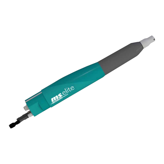
Page 19: Ms Elite A5 Automatic Powder Applicator Parts Breakdown
INTRODUCTION Return To Contents Figure 1: MS elite A5 Automatic Powder Applicator 835020 MS ELITE A5 AUTOMATIC POWDER APPLICATOR Item # Description Housing, A5 elite Cap, End, A5 Nut, Nozzle Flat spray nozzle Clip, Body 5 Pin Applicator Cable Connector... -
Page 20: Function
INTRODUCTION Return To Contents FUNCTION Since these particles have the same charge as the spray When the automatic powder spray applicator is turned on at applicator, they are repelled, distributed in a fine cloud and the controller, and the cable is connected at (1), the cascade (2) is activated and provides high voltage to the electrode. -
Page 21: Nozzle Function
INTRODUCTION Return To Contents NOZZLE FUNCTION Flat fan nozzle The applicator air is used to cool the electrode during operation to prevent impact fusion. Applicator Air High Voltage Round spray nozzle The applicator air is used to cool the electrode during operation to prevent impact fusion. -
Page 22: Installation
INSTALLATION Return To Contents INSTALLATION COMMISSIONING AND 3. In case of a problem with the equipment, the issue must be solved as described in the maintenance section under OPERATION OF MS ELITE troubleshooting. A5 AUTOMATIC POWDER APPLICATOR 4. Comply with local regulations for occupational safety and accident prevention regulations at all times. -
Page 23: Cable And Hose Connections
INSTALLATION CABLE AND HOSE CONNECTIONS CONNECTING Connect From Connecting to Controller Manual Powder Applicator Cable Applicator Connect Powder Applicator Controller Dosage Air Hose Doseage Air Red Controller Injector Dosage Air Feed Air Hose Feed Air Blue Controller Injector Feed Air Gun Air Hose Rinse Air Black Controller... -
Page 24: Wiring Diagram Of Ms Elite Control Module (Basic Model)
INSTALLATION WIRING DIAGRAM OF MS ELITE CONTROL MODULE (BASIC MODEL) Vibrator Control Signals 24VDC 230/110V 50/60Hz 6 bar Inlet (87 psig) Air Pressure (max) PA-18-01-R5 (02/2022) 24 / 41 www.carlisleft.com... -
Page 25: Wiring Diagram Of Ms Elite Control Module (Deluxe Model)
INSTALLATION Return To Contents WIRING DIAGRAM OF MS ELITE CONTROL MODULE (DELUXE MODEL) Vibrator Control Signals 24VDC 230/110V 50/60Hz 6 bar Inlet (87 psig) Air Pressure (max) www.carlisleft.com 25 / 41 PA-18-01-R5 (02/2022) -
Page 26: Tubing Diagram For Use With 610190-10
INSTALLATION TUBING DIAGRAM FOR USE WITH 610190-10 Supply 6 bar Inlet (87 psig) Air Pressure (max) PA-18-01-R5 (02/2022) 26 / 41 www.carlisleft.com... -
Page 27: Connecting Automatic Powder Applicator
INSTALLATION Return To Contents CONNECTABLE CONTROLLERS CONNECTING AUTOMATIC MS elite AUTOMATIC POWDER APPLICATOR POWDER APPLICATOR The powder hose is connected via a quick disconnect. There is a gun air fitting and the controller cable connection. The MS elite Automatic powder spray applicator may only be operated with one of the following controllers: WA R N I N G •... -
Page 28: Operation
OPERATION Return To Contents OPERATION GROUNDING WA R N I N G Ground the powder coating system properly. † The grounding of all conductive parts (for example, hooks, chain conveyors, etc.) must be checked at least In order to achieve a good powder coating and for safety weekly. -
Page 29: Maintenance
MAINTENANCE Return To Contents MAINTENANCE NOZZLE CHANGE WA R N I N G Removing the nozzle † Inspection and maintenance of this equipment shall be carried out by suitably trained personel. WA R N I N G † Wear parts in the powder applicator, marked with a W in the spare parts list, must be checked regularly and replaced if necessary. -
Page 30: Cleaning Powder Passage
MAINTENANCE Return To Contents 4. Carefully pull out the nozzle tube (3) without twisting the applicator body (4). 2. Screw the nozzle nut (2) over the nozzle tube (3). Replace 5. Clean the removed nozzle and powder applicator with the flat spray nozzle (1). Check the nozzle slot is aligned compressed air. - Page 31 MAINTENANCE Return To Contents 3. Remove cover and powder connector assembly. 6. Apply dielectric grease along the cascade wire and body. 7. Reinsert cascade, taking care to orient wire correctly. 4. Remove cascade assembly. 8. Replace rear cover and powder tube assembly. 5.
-
Page 32: Troubleshooting Guide
MAINTENANCE Return To Contents TROUBLESHOOTING GUIDE General Problem Possible Cause Solution Wear bar or flat spray nozzle are improperly Inconsistent See “Installing the Nozzle” section. oriented Powder Cloud Improper power cord connection. No Power or Check plug connections. Air Delivery applicator Improper controller/ cable connection. -
Page 33: Parts Identification
PARTS IDENTIFICATION Return To Contents PARTS IDENTIFICATION 460105 615214 615056 615258 460230 419738 460485 461601 427061 615057 (Included in 615258) (Includes 615258) (Fastened by 419750) 621211 615214 615258 461775 615213 615277 615260-00 MS TOPCOAT A5 AUTOMATIC APPLICATOR SPARE PARTS Part # Description Wear Part 460230... - Page 34 PARTS IDENTIFICATION 615218 460450 460430 460440 460460 615219-01 615260-00 461775 615213 ROUND SPRAY NOZZLES “R” Part # Description 615218 Round Spray Nozzle Set R1 460430 Round Spray Nozzle D16 (Included in 615218) 460440 Round Spray Nozzle D20 (Included in 615218) 460450 Round Spray Nozzle D24 (Included in 615218) 460460...
-
Page 35: Accessories
PARTS IDENTIFICATION ACCESSORIES 615214 615277 615258 461775 615260-00 615213 FLAT SPRAY NOZZLES “C3” Description Part # 615214 Assembly, Flat Spray Nozzle & Electrode 615258 Assembly, Flat Spray Nozzle (Included in 615214) 460105-K5, -K25, -K50 O-Ring Nozzle Kit 615260-00, -K5 Wire Assembly Kit 615277, -K5 Electrode Replacement Kit 615213... -
Page 36: Flat Nozzle Extensions
PARTS IDENTIFICATION Return To Contents POWDER HOSE Part # Description 810195-06 Powder Hose 6m, (10mm ID) 810195-08 Powder Hose 8m, (10mm ID) 810195-10 Powder Hose 10m, (10mm ID) 810195-16 Powder Hose 16m, (10mm ID) 810190-20 Powder Hose 20m, (11mm ID) 810195-100 Powder Hose 100m, Bulk (10mm ID) 810190-100... - Page 37 PARTS IDENTIFICATION Return To Contents 615215 (150mm) 615216 (300mm) 615258 615239 (150mm) 615240 (300mm) 461866 615000-150 (150mm) 615000-300 (300mm) 615212 615330-03 (150mm) 615213 615330-01 (300mm) 615258 461888 FLAT SPRAY NOZZLE EXTENSIONS “C3” Part # Description 615215 Assembly, Nozzle Extension Flat Spray Set, 150mm 615239 Assembly, Extension Tube 150mm 615000-150...
- Page 38 PARTS IDENTIFICATION Return To Contents 615050-1X (150mm) 615050-3X (300mm) 615130-X 615239 (150mm) 615240 (300mm) 615000-150 (150mm) 461866 (O-RING) 615000-300 (300mm) 615330-03 (150mm) 615212 615330-01 (300mm) 615213 461888 615130-X FLAT SPRAY NOZZLE EXTENSIONS “G” Part # Description Assembly, Nozzle Extension Flat Jet Set, 150mm 615050-13 Nozzle Extension Flat Jet Set, 150mm (3mm wide) 615050-14...
- Page 39 PARTS IDENTIFICATION 615225 (150mm) 615226 (300mm) 615239 (150mm) 461866 (O-RING) 615213 615240 (300mm) 615219-02 (150mm) 460430 460440 460450 460460 615219-03 (300mm) 615330-04 (150mm) 615330-02 (300mm) 461888 ROUND SPRAY NOZZLE EXTENSIONS “R” Part # Description 615225 Assembly, Nozzle Extension Round Spray Set, 150mm 615239 Assembly, Extension Tube 150mm 615330-04, -K5...
-
Page 40: Manual Changes
MANUAL CHANGES Return To Contents MANUAL CHANGE SUMMARY PA-18-01-R5 - Replaces PA-18-01-R4 with the folowing changes: Change Description Page(s) 1. Update SAFETY section 2. Make multiple changes to ATEX/FM/UKEX section 13-17 3. Text change to bullet point 3 4. Change MANUAL to AUTOMATIC, redirect arrows in the image and change last WARNING to a CAUTION 5. - Page 41 WARRANTY POLICY This product is covered by Carlisle Fluid Technologies’ materials and workmanship limited warranty. The use of any parts or accessories, from a source other than Carlisle Fluid Technologies, will void all warranties. Failure to reasonably follow any maintenance guidance provided, may invalidate any warranty.
Need help?
Do you have a question about the MS Elite A5 and is the answer not in the manual?
Questions and answers