Table of Contents
Advertisement
Quick Links
UM11436
PCA9959 Evaluation board OMPCA9959LEDEV
Rev. 1.0 — 27 April 2020
Document information
Information
Content
Keywords
SPI-bus, PCA9959, RGB and White LEDs, 24-channel x 6-bit brightness, 64
grids for gradation control.
Abstract
The OMPCA9959LEDEV eval board allows test and design for the PCA9959,
which is a 24-channel SPI 4-wire bus 63 mA/5.5V constant current LED
driver. This eval board, along with the OM13089 MCU board, provides an
easy to use evaluation platform.
User manual
Advertisement
Table of Contents

Related Manuals for NXP Semiconductors UM11436


Summary of Contents for NXP Semiconductors UM11436
- Page 1 UM11436 PCA9959 Evaluation board OMPCA9959LEDEV Rev. 1.0 — 27 April 2020 User manual Document information Information Content Keywords SPI-bus, PCA9959, RGB and White LEDs, 24-channel x 6-bit brightness, 64 grids for gradation control. Abstract The OMPCA9959LEDEV eval board allows test and design for the PCA9959, which is a 24-channel SPI 4-wire bus 63 mA/5.5V constant current LED...
- Page 2 UM11436 NXP Semiconductors PCA9959 Evaluation board OMPCA9959LEDEV Revision history Revision history Date Description v.1.0 20200427 Initial version UM11436 All information provided in this document is subject to legal disclaimers. © NXP B.V. 2020. All rights reserved. User manual Rev. 1.0 — 27 April 2020...
-
Page 3: Introduction
UM11436 NXP Semiconductors PCA9959 Evaluation board OMPCA9959LEDEV Introduction The PCA9959 evaluation board features LEDs for color mixing, blinking and dimming demonstrations. A graphical interface allows the user to easily explore the different functions of the driver. The board can be connected in series with other SPI-bus demo- boards to create an evaluation system. -
Page 4: Features
UM11436 NXP Semiconductors PCA9959 Evaluation board OMPCA9959LEDEV Features • A complete evaluation platform for the PCA9959 24-channel SPI-bus 63 mA/5.5V constant current LED driver • Easy to use GUI based software demonstrates the capabilities of the PCA9959. • On-board Infrared, blue and RGB LEDs for variable experiments •... -
Page 5: Getting Started
UM11436 NXP Semiconductors PCA9959 Evaluation board OMPCA9959LEDEV Getting started 3.1 Assumptions Familiarity with the SPI-bus is helpful but not required. 3.2 Static handling requirements CAUTION This device is sensitive to ElectroStatic Discharge (ESD). Therefore care should be taken during transport and handling. You must use a ground strap or touch the PC case or other grounded source before unpacking or handling the hardware. -
Page 6: Hardware Installation
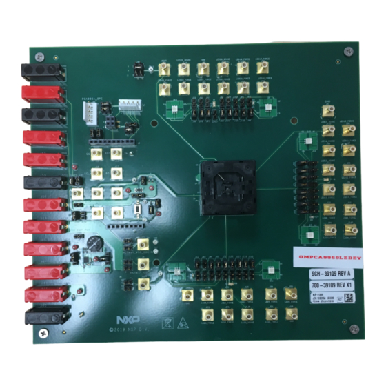
UM11436 NXP Semiconductors PCA9959 Evaluation board OMPCA9959LEDEV Hardware installation 4.1 OMPCA9959LEDEV EV board and OM13089 MCU board connection OMPCA9959LEDEV evaluation board is connected to the OM13089 MCU board using two connectors (J1 & J2 on OMPCA9959LEDEV board and J1 & J8 on OM13089 board). - Page 7 UM11436 NXP Semiconductors PCA9959 Evaluation board OMPCA9959LEDEV Figure 2. OM13089 MCU board • OMPCA9959LEDEV evaluation board connecting to the OM13089 MCU board • Use J5 (USB Micro-B connector) on OM13089 for power supply and GUI communication port. • Use J7 (USB Micro-B connector) on OM13089 for additional power supply Figure 3. OMPCA9959LEDEV evaluation board...
-
Page 8: Hardware Description
UM11436 NXP Semiconductors PCA9959 Evaluation board OMPCA9959LEDEV Hardware description • J1 and J2 are connected to the PM13089 MCU board. • J123 selects PCA9959 VDD power supply. • J120 selects PCA9959 VDDIO power supply. • J113 selects LED power supply. - Page 9 UM11436 NXP Semiconductors PCA9959 Evaluation board OMPCA9959LEDEV Jumper Default setting Comment SPI bus interface to the OM13089 MCU board J3, J4 For OMPCA9959LEDEV SPI daisy chain test MISO MOSI SPI bus test points J8,J9,J10,J11 SPI bus SPI bus test points Table 4. Jumper settings for LEDs...
- Page 10 UM11436 NXP Semiconductors PCA9959 Evaluation board OMPCA9959LEDEV Jumper Default setting Comment D12 - RGB LED 1-2: Not measuring D12 current Open: Use current J75, J77, J80 meter to measure D12 current J76, J78, J79 Open D12 - RGB LED 1-2: Bypass D12 LED Open: Use D12 LED...
- Page 11 UM11436 NXP Semiconductors PCA9959 Evaluation board OMPCA9959LEDEV Figure 4. Jumpers and test points location UM11436 All information provided in this document is subject to legal disclaimers. © NXP B.V. 2020. All rights reserved. User manual Rev. 1.0 — 27 April 2020...
-
Page 12: Schematic
UM11436 NXP Semiconductors PCA9959 Evaluation board OMPCA9959LEDEV Schematic VDD Ext Power Supply (2.7V - 5.5V) VDDIO Ext Power Supply (1.65V - 5.5V) J124 HDR 1X2 TH VDDIO Power Supply From VDD_IN or EXT power SILK = VDD EXT PWR J121... - Page 13 UM11436 NXP Semiconductors PCA9959 Evaluation board OMPCA9959LEDEV TP16 +5V_MCU J113 LED voltage select: OPEN: use external voltage TP15 VOUT_ADJ 1-2: +5V 2-3: +3.3V 2-4: +2.5V to +4.1V +3V3_MCU OUT1 OUT2 HDR 1X1 + HDR 1X3 OUT3 JUMPER DEFAULT = 2-4...
- Page 14 UM11436 NXP Semiconductors PCA9959 Evaluation board OMPCA9959LEDEV LED[0..23] LED[0..23] [2,3] VDDIO CON 1 SMB CON 1 SMB CON 1 SMB CON 1 SMB CON 1 SMB CON 1 SMB CON 1 SMB CON 1 SMB CON 1 SMB CON 1 SMB...
-
Page 15: Pca9959 Demo Gui
UM11436 NXP Semiconductors PCA9959 Evaluation board OMPCA9959LEDEV PCA9959 demo GUI 7.1 Run PCA9959 GUI V0.1.exe on Windows 7, 8, or 10 PC 1. Click “Connect” button to connect OM13089 board 2. If OM13089 board is detected a. It shows “OM13089 board connected” in Message Box b. - Page 16 UM11436 NXP Semiconductors PCA9959 Evaluation board OMPCA9959LEDEV 3. If OM13089 board is not detected a. It shows “OM13089 (LPC 54114) board doesn't find!” in Message Box. b. Please check whether USB cable is connected to right USB port (J5) on OM13089 board 4.
- Page 17 UM11436 NXP Semiconductors PCA9959 Evaluation board OMPCA9959LEDEV 6. Use “GRID0-7” to “GRID56-63” to adjust GRID0 – GRID63 setting a. Use GRID0 – GRID63 Combo Box to adjust GRIDx value 7. Use “CH0_CFG-CH11_CFG” and “CH12_CFG-CH23” LED CHx output a. Use CHx checkbox to enable or disable LED CHx output b.
- Page 18 UM11436 NXP Semiconductors PCA9959 Evaluation board OMPCA9959LEDEV 8. Use “Error Flags” page to read out error status for LEDs output a. Click on “Read Error Flags” button to read out error status for LED0-23 output b. Click on “CLRERR” button to clear error flags.
- Page 19 UM11436 NXP Semiconductors PCA9959 Evaluation board OMPCA9959LEDEV UM11436 All information provided in this document is subject to legal disclaimers. © NXP B.V. 2020. All rights reserved. User manual Rev. 1.0 — 27 April 2020 19 / 25...
-
Page 20: Abbreviations
UM11436 NXP Semiconductors PCA9959 Evaluation board OMPCA9959LEDEV Abbreviations Table 7. Abbreviations Acronym Description Electro Static Discharge Graphical User Interface C-bus Inter-integrated Circuit bus Integrated Circuit Light Emitting Diode MISO Master In, Slave Out MOSI Master Out, Slave In Personal Computer Pulse Width Modulator... -
Page 21: References
UM11436 NXP Semiconductors PCA9959 Evaluation board OMPCA9959LEDEV References PCA9959 — 24-channel SPI serial bus 32 mA / 5.5V constant current LED driver; Product data sheet; NXP Semiconductors UM11436 All information provided in this document is subject to legal disclaimers. © NXP B.V. 2020. All rights reserved. -
Page 22: Legal Information
Customer is responsible for doing all necessary testing for the customer’s applications and products using NXP Semiconductors products in order to avoid a 10.2 Disclaimers default of the applications and the products or of the application or use by customer’s third party customer(s). - Page 23 UM11436 NXP Semiconductors PCA9959 Evaluation board OMPCA9959LEDEV Tables Tab. 1. OMPCA9959LEDEV board main Tab. 4. Jumper settings for LEDs ........9 components ............8 Tab. 5. Jumper settings for SMB connectors ....10 Tab. 2. Jumper settings for power supply ..... 8 Tab.
- Page 24 UM11436 NXP Semiconductors PCA9959 Evaluation board OMPCA9959LEDEV Figures Fig. 1. OMPCA9959LEDEV evaluation board ....6 Fig. 5. PCA9959 schematic ........12 Fig. 2. OM13089 MCU board ........7 Fig. 6. LED portion schematic ........13 Fig. 3. OMPCA9959LEDEV evaluation board ....7 Fig.
-
Page 25: Table Of Contents
'Legal information'. © NXP B.V. 2020. All rights reserved. For more information, please visit: http://www.nxp.com For sales office addresses, please send an email to: salesaddresses@nxp.com Date of release: 27 April 2020 Document identifier: UM11436...
Need help?
Do you have a question about the UM11436 and is the answer not in the manual?
Questions and answers