Table of Contents
Advertisement
Quick Links
Advertisement
Chapters
Table of Contents

Related Manuals for Rohde & Schwarz R&S NRPM


Summary of Contents for Rohde & Schwarz R&S NRPM
- Page 1 ® R&S NRPM OTA Power Measurement Solution User Manual (>IäÍ2) 1425866302...
- Page 2 ® This document describes the R&S NRPM OTA Power Measurement Solution, including the following com- ponents: ● ® R&S NRPM3 Sensor Module, 1425.8563.02 ● ® R&S NRPM-A90 OTA Single Polarized Antenna Module, 1426.7760.02 ● ® R&S NRPM-A90D OTA Dual Polarized Antenna Module, 1426.7777.02 ●...
- Page 3 Safety Instructions Instrucciones de seguridad Sicherheitshinweise Consignes de sécurité Risk of injury and instrument damage The instrument must be used in an appropriate manner to prevent electric shock, fire, personal injury or instrument damage. ● Do not open the instrument casing. ●...
- Page 4 Gefahr von Verletzungen und Schäden am Gerät Betreiben Sie das Gerät immer ordnungsgemäß, um elektrischen Schlag, Brand, Verletzungen von Personen oder Geräteschäden zu verhindern. ● Öffnen Sie das Gerätegehäuse nicht. ● Lesen und beachten Sie die "Grundlegenden Sicherheitshinweise", die als gedruckte Broschüre dem Gerät beiliegen. ●...
-
Page 5: Table Of Contents
® Contents R&S NRPM Contents 1 Welcome to the R&S NRPM OTA Power Measurement Solution..7 2 Preface....................9 About this Manual......................9 Documentation Overview................... 10 2.2.1 User Manual........................10 2.2.2 Basic Safety Instructions....................10 2.2.3 Data Sheets and Brochures..................10 2.2.4 Release Notes and Open Source Acknowledgment (OSA).......... 10 3 Preparing for Use................. - Page 6 ® Contents R&S NRPM 5 Performing Measurements..............33 Sensor Module Readings................... 33 Measurement Applications..................33 5.2.1 Using R&S Power Viewer....................34 5.2.2 Using R&S Forum......................39 5.2.3 References........................41 6 Firmware Update.................. 43 Installation of New Firmware..................43 Hardware and Software Requirements..............43 Preparation........................
- Page 7 ® Contents R&S NRPM 7.6.1 Configuring Auto Averaging..................83 7.6.2 Setting the Frequency....................87 7.6.3 Configuring Corrections....................87 7.6.3.1 Duty Cycle Corrections....................87 7.6.3.2 Offset Corrections......................88 Starting and Ending a Measurement.................89 Configuring the Trigger....................90 Using the Status Register..................97 7.9.1 General Status Register Commands................
- Page 8 ® Contents R&S NRPM A.2.3 Status Byte (STB) and Service Request Enable Register (SRE)........ 119 A.2.4 IST Flag and Parallel Poll Enable Register (PPE)............121 A.2.5 Device Status Register....................121 A.2.6 Questionable Status Register..................122 A.2.6.1 Questionable Power Status Register................123 A.2.6.2 Questionable Calibration Status Register..............
-
Page 9: Welcome To The R&S Nrpm Ota Power Measurement Solution
® Welcome to the R&S NRPM OTA Power Measurement Solution R&S NRPM 1 Welcome to the R&S NRPM OTA Power Measurement Solution The R&S NRPM OTA power measurement solution is designed to calibrate the trans- mit antenna output power and test the beamforming function over the air. Applications are in high frequency bands, used in modern high performance wireless system stand- ards, e.g. - Page 10 ® Welcome to the R&S NRPM OTA Power Measurement Solution R&S NRPM With the single and dual polarized antenna modules (R&S NRPM-A90, R&S NRPM- A90D), you can calibrate the DUT (transmit antenna) output power and test the beam- forming function. The R&S NRPM measurement is controlled by an arbitrary user-definable measure- ment application.
-
Page 11: Preface
® Preface R&S NRPM About this Manual 2 Preface The R&S NRPM OTA power measurement solution is designated for the development, production and verification of electronic components and devices in industrial and labo- ratory environments. Always operate the system in an EM controlled environment, i.e. in an RF test box or RF test chamber. -
Page 12: Documentation Overview
® Preface R&S NRPM Documentation Overview ● Glossary List of often used terms and abbreviations. ● Index Details concerning the arrangement of the antenna modules in the test setup are not discussed in this manual. 2.2 Documentation Overview This section provides an overview of the R&S NRPM user documentation. Unless specified otherwise, you find the documents on the product page at: www.rohde- schwarz.com/manual/nrpm. -
Page 13: Preparing For Use
® Preparing for Use R&S NRPM 3 Preparing for Use This section describes the basic steps to be taken when setting up the R&S NRPM OTA power measurement solution for the first time. Risk of injury due to disregarding safety information Observe the information on appropriate operating conditions provided in the data sheet to prevent personal injury or damage to the instrument. -
Page 14: Emi Suppression
® Preparing for Use R&S NRPM Unpacking and Checking the Instrument Risk of instrument damage during operation An unsuitable operating site or test setup can damage the sensor module and connec- ted devices. Make sure that the following operating conditions are met: ●... -
Page 15: R&S Nrpm Tour
® Preparing for Use R&S NRPM R&S NRPM Tour 3.3 R&S NRPM Tour The following chapters introduce the main hardware components of the R&S NRPM OTA power measurement solution. 3.3.1 R&S NRPM3 Sensor Module This chapter provides an overview of the available connectors and LED of the R&S NRPM3. -
Page 16: R&S Nrpm-A90 And R&S Nrpm-A90D Antenna Modules
® Preparing for Use R&S NRPM R&S NRPM Tour Trigger I/O connector (3) The trigger I/O is a connector of SMB type. You can use the connector for input or output of a trigger signal, and for working in trig- ger master-slave mode (optional), see also "Host interface connector (2)"... - Page 17 ® Preparing for Use R&S NRPM R&S NRPM Tour R&S NRPM-A90 Single polarized antenna module with integrated diode detector 1 = PCB (printed circuit board) 2 = Signaling LED 3 = Interface cable R&S NRPM-A90D Dual polarized antenna module with integrated diode detectors 1 = PCBs (printed circuit boards) To distinguish the feeds, the carrier of the R&S NRPM-A90D antenna module is labeled on the back with the corresponding let-...
-
Page 18: R&S Nrpm-Zd3 Feedthrough Module
® Preparing for Use R&S NRPM R&S NRPM Tour Printed circuit boards of the antenna modules (1) Risk of antenna module damage when touching the PCB of the antenna mod- ules (1) Never touch the exposed top or bottom of the antenna module PCB (printed circuit board) during setting up. -
Page 19: R&S Nrpm-Z3 Interface Module
® Preparing for Use R&S NRPM R&S NRPM Tour Figure 3-2: The R&S NRPM-ZD3 feedthrough module 1 = Cable feedthrough module 2 = Antenna module cable connectors 3 = Sensor module cable connector Filtered cable feedthrough module (1) R&S NRPM-ZD3 filtered cable feedthrough for combining three antenna module cables to one sensor module cable R&S NRPM-ZKD3. -
Page 20: R&S Nrpm-Z3 Connected To The R&S Nrpm3
® Preparing for Use R&S NRPM R&S NRPM Tour Figure 3-3: The R&S NRPM-Z3 interface module 1 = Interface module 2 = Connector to sensor module 3 = Antenna module cable connectors Interface module (1) R&S NRPM-Z3 three channel interface module to pass up to three antenna module cables to one R&S NRPM3 sensor module. -
Page 21: Hardware And Software Requirements
® Preparing for Use R&S NRPM Hardware and Software Requirements 1 = R&S NRP-ZKU 2 = R&S NRPM3 3 = R&S NRPM-Z3 4 = Strain relieve 5 = Antenna module cables Strain relieve (4) Strain relieve for the antenna module cable connections. Antenna module cables (5) Cables firmly connected to the antenna modules for connection to the R&S NRPM-Z3 interface module or the R&S NRPM-ZD3 feedthrough interface modules. -
Page 22: Mandatory Software
® Preparing for Use R&S NRPM Hardware and Software Requirements Chapter 4, "Setting Up a Measurement", on page 27 for examples on how to set up an R&S NRPM OTA power measurement. 3.4.2 Mandatory Software The sensor modules are smart sensor modules that can be directly connected to a controlling PC. -
Page 23: Installing The Software Application And Drivers
® Preparing for Use R&S NRPM Installing the Software Application and Drivers dows command syntax) to complex programs using the programming language Python. ● Programming examples for customer-specific applications. Rohde & Schwarz provides various programming examples containing: – The GUI application R&S Power Viewer. –... -
Page 24: Visa Driver Installation
® Preparing for Use R&S NRPM Installing the Software Application and Drivers 3.5.1 VISA Driver Installation To install the R&S VISA standardized software library on MS Windows: ► Consult the Rohde & Schwarz http://www.rohde-schwarz.com/rsvisa web site, that provides the software and the necessary information. If you are using VISA from another supplier, refer to the corresponding documenta- tion on how to install the driver on your system. - Page 25 ® Preparing for Use R&S NRPM Installing the Software Application and Drivers 3. In the main dialog: a) Select the R&S NRP Toolkit 64-bit option if your MS Windows PC has 64-bit architecture. The 32-bit version is always installed. b) To include the programming examples, select "NRP-Toolkit SDK". To develop own application programs with the R&S NRPM3, we recommend that you acti- vate this option to get various programming samples installed onto your PC.
- Page 26 ® Preparing for Use R&S NRPM Installing the Software Application and Drivers 2. The corresponding packages come with a README.txt file which describes in detail the steps to install the Linux R&S NRP Toolkit. An R&S NRP Toolkit for Linux normally consists of several files (*.deb or *.rpm files).
-
Page 27: R&S Power Viewer Installation
® Preparing for Use R&S NRPM Installing the Software Application and Drivers 3.5.3 R&S Power Viewer Installation The R&S Power Viewer is a software application that simplifies many power measure- ment tasks. It is part of the Mac OS X NRP-Toolkit installer, and is available as a sepa- rately installable package for Linux and MS Windows. - Page 28 ® Preparing for Use R&S NRPM Installing the Software Application and Drivers R&S Forum must be installed on the PC, and requires a VISA library, e.g. the R&S VISA. If there is no VISA library available on the PC, you can include the R&S VISA during R&S Forum installation.
-
Page 29: Setting Up A Measurement
® Setting Up a Measurement R&S NRPM 4 Setting Up a Measurement This section shows some test setup examples and brief instructions on how to connect the components of an OTA power measurement. You can also find references to the product page and the user manual of the RF test box R&S TS7124 or the RF test chamber R&S ATS1000. - Page 30 ® Setting Up a Measurement R&S NRPM Example: Setup with one single polarized R&S NRPM-A90 antenna module installed in an RF test box (feedthrough module): Figure 4-1: One R&S NRPM-A90 in an RF test box Multiple spatially distributed antenna modules With several antenna modules distributed in an area, you can test the beamforming function of a DUT.
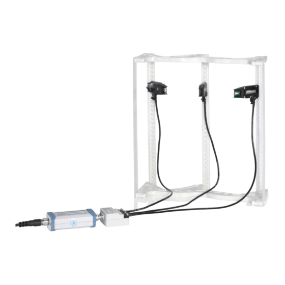
- Page 31 ® Setting Up a Measurement R&S NRPM Example: Setup with multiple single polarized R&S NRPM-A90 antenna modules in an RF test chamber (interface modules): Figure 4-3: Multiple R&S NRPM-A90 in an RF test chamber Example: Setup with dual polarized R&S NRPM-A90D antenna modules in an RF test box with feedthrough modules: Figure 4-4: Setup with multiple R&S NRPM-A90D in an anechoic chamber Note: Since one dual polarized antenna module allocates two channels of the sensor...
-
Page 32: R&S Ts7124 Rf Test Box
® Setting Up a Measurement R&S NRPM Connecting the R&S NRPM3 4.1 R&S TS7124 RF Test Box The R&S TS7124 RF test box enables reliable and reproducible measurements when a controlled EM test environment is needed. As the R&S TS7124 is a stand-alone product of Rohde & Schwarz, this section does not describe the box and measurement setups in detail. - Page 33 ® Setting Up a Measurement R&S NRPM Connecting the R&S NRPM3 ● The software and drivers are installed on the controller PC, see Chapter 3.5, "Installing the Software Application and Drivers", on page 21. ● The transmitting device (DUT) is installed and ready for operation. The following steps describe the connections necessary for measurement setups in both, an RF test box or an RF test chamber.
- Page 34 ® Setting Up a Measurement R&S NRPM Connecting the R&S NRPM3 When you are working with the dual-polarized antenna modules R&S NRPM- A90D, notice the feeds of the vertical and horizontal antenna modules. You can find out the alignment with the identification numbers "1" (vertical) and "2" (horizon- tal) on the carrier of the antenna modules.
-
Page 35: Performing Measurements
® Performing Measurements R&S NRPM Measurement Applications 5 Performing Measurements 5.1 Sensor Module Readings The antenna modules R&S NRPM-A90 and R&S NRPM-A90D have integrated diode detectors that convert the RF signal and transmit it directly to the sensor module. You can measure the power of the incident electromagnetic wave towards the antenna module in various quantities: ●... -
Page 36: Using R&S Power Viewer
® Performing Measurements R&S NRPM Measurement Applications It is assumed, that the measurement is set up, and the required software and drivers are installed on the PC. 5.2.1 Using R&S Power Viewer This section shows how to start the application and access the settings relevant for OTA measurements. - Page 37 ® Performing Measurements R&S NRPM Measurement Applications 2. In the lower border toolbar, select the sensor module. 3. In the panel on the right, select the antenna modules for the measurement. 4. If necessary, set the parameters to configure the continuous average power mea- surement.
- Page 38 ® Performing Measurements R&S NRPM Measurement Applications The measurement results window displays measured power in the sensor module channels. To configure an OTA multi sensor ContAV measurement In the toolbar, select the "OTA Multi Sensor" button to open the panel for the OTA measurements with several sensor modules.
- Page 39 ® Performing Measurements R&S NRPM Measurement Applications The measurement results window displays the results of the multi channel mea- surement. To configure an OTA single sensor trace power measurement In the toolbar, select the button to open the panel for trace measurements. User Manual 1425.8663.02 ─...
- Page 40 ® Performing Measurements R&S NRPM Measurement Applications The R&S Power Viewer displays the trace measurement results windows, and the setting parameters in the panel on the right. 2. In the lower border toolbar, select the sensor module. 3. In the panel on the right, select the antenna modules for the measurement. 4.
-
Page 41: Using R&S Forum
® Performing Measurements R&S NRPM Measurement Applications The results window displays the trace measurement results of the three antenna modules. 5.2.2 Using R&S Forum With the scripting tool R&S Forum, you can measure the power in remote control mode. This section briefly shows how to proceed by a programming example. For han- dling and using the tool in detail, see the documentation provided at the www.rohde- schwarz.com/forum... - Page 42 ® Performing Measurements R&S NRPM Measurement Applications 4. Enter the resource parameters. 5. Confirm with "Ok". 6. In the "Enabled" column, check the R&S NRPM3. 7. Select "Test Connection". R&S Forum confirms the connection by displaying the response of the sensor mod- ule.
-
Page 43: References
® Performing Measurements R&S NRPM Measurement Applications 8. Close the dialog with "Ok". In the interface window, you can control the R&S NRPM3 using single commands, command sequences or executing loaded script files. Figure 5-1: R&S Forum interface window 5.2.3 References This section provides information on starting the R&S Power Viewer on operating sys- tems other than MS Windows. - Page 44 ® Performing Measurements R&S NRPM Measurement Applications 4. Double-click "Power Viewer.app" 5. Connect the sensor modules to a USB port of your system. The measurement is set up and ready for operation. Using R&S Power Viewer on Linux The Linux version of R&S Power Viewer is available as an installable package for selected Linux distributions.
-
Page 45: Firmware Update
® Firmware Update R&S NRPM Preparation 6 Firmware Update 6.1 Installation of New Firmware Use the firmware update program (PureFW) to load new firmware for the sensor mod- ules. It is part of the R&S NRP Toolkit that is provided on the Internet, e.g. on the www.rohde-schwarz.com/software/nrpm/ website. -
Page 46: Updating The Application Firmware
® Firmware Update R&S NRPM Updating the Application Firmware 6.4 Updating the Application Firmware To perform a firmware update: 1. Start the firmware update program (PureFW) via "Start menu > NRP-Toolkit > Firm- ware Update". The following window appears: The program automatically starts scanning for R&S NRPM3 sensor modules which are connected via USB. - Page 47 ® Firmware Update R&S NRPM Updating the Application Firmware The "Hostname or IP Address" field is for adding sensor modules which are con- nected to the LAN. Since there is no LAN version of the sensor module, this field is not used.
- Page 48 ® Firmware Update R&S NRPM Updating the Application Firmware Potential damage to the firmware of the device Disconnecting the power supply while an update is in progress leads to missing or faulty firmware. Special care must be taken on not disconnecting the power supply while the update is in progress.
-
Page 49: Remote Control
® Remote Control R&S NRPM Remote Control Commands 7 Remote Control 7.1 Remote Control Commands In the following sections, all commands implemented in the sensor are listed according to the command system and then described in detail. Mostly, the notation used com- plies with SCPI specifications. - Page 50 ® Remote Control R&S NRPM Remote Control Commands Numeric suffixes <n> If a command can be applied to multiple instances of an object, e.g. specific sensor modules, the required instances can be specified by a suffix added to the command. Numeric suffixes are indicated by angular brackets (<1...4>, <n>, <I>) and are replaced by a single value in the command.
-
Page 51: Common Commands
® Remote Control R&S NRPM Remote Control Commands Special characters | and { } A vertical bar in parameter definitions indicates alternative possibilities in the sense of "or". The effect of the command differs, depending on which parameter is used. Example: Definition: INITiate:CONTinuous ON | OFF Command INITiate:CONTinuous ON starts the measurements... -
Page 52: Ese
® Remote Control R&S NRPM Remote Control Commands *ESE <register> Event Status Enable Sets the event status enable register to the specified value. The query returns the con- tents of the event status enable register in decimal form. Parameters: <register> Range: 0 to 255 *RST:... -
Page 53: Opt
® Remote Control R&S NRPM Remote Control Commands *OPC? is preferred to because with *OPC?, the execution of commands can be *WAI queried from a controller program before new commands are sent. This prevents over- flow of the input queue when too many commands are sent that cannot be executed. Unlike *WAI, *OPC? must be sent at the end of a program message. -
Page 54: Sre
® Remote Control R&S NRPM Remote Control Commands Stores the current device state under the specified number. The storage numbers 0 to 9 are available. Setting parameters: <number> Range: 0 to 9 *RST: Usage: Setting only *SRE <register> Service Request Enable Sets the service request enable register to the specified value. -
Page 55: Configuring The General Functions
® Remote Control R&S NRPM Configuring the General Functions Example: *TST? Query Response: Passed *TST? Query Response: Failed Usage: Query only *WAI WAIt to continue Prevents the execution of the subsequent commands until all preceding commands have been executed and all signals have settled. Usage: Event 7.2 Configuring the General Functions... -
Page 56: System:dfprint
® Remote Control R&S NRPM Configuring the General Functions ..................59 SYSTem:PARameters:DELTa? ......................59 SYSTem:PRESet ......................60 SYSTem:REBoot ......................60 SYSTem:RESTart ..................... 60 SYSTem:SERRor:LIST:ALL? ..................60 SYSTem:SERRor:LIST[:NEXT]? ......................60 SYSTem:SERRor? ......................61 SYSTem:TLEVels? ................... 61 SYSTem:TRANsaction:BEGin ....................61 SYSTem:TRANsaction:END ......................61 SYSTem:VERSion? ....................61 SYSTem[:SENSor]:NAME SYSTem:DFPRint<Channel>? Reads the footprint file of the sensor module. -
Page 57: System:error:count
® Remote Control R&S NRPM Configuring the General Functions Example: SYSTem:ERRor:CODE? Response: 0 No errors have occurred since the error queue was last read out. Usage: Query only SYSTem:ERRor:COUNt? Queries the number of entries in the error queue. Example: SYSTem:ERRor:COUNt? Response: 1 One error occurred since the last read out of the error queue. -
Page 58: System:fwupdate:status
® Remote Control R&S NRPM Configuring the General Functions Example: If you want to update the firmware of the R&S NRPM, you first need an update file, e.g. nrpm3_FW_15.02.12.01.rsu. Lets assume that this file has a size of 10242884 bytes. To send the file to the sensor module for updating the firmware to the new one, your application must assemble a memory block. -
Page 59: System:help:headers
® Remote Control R&S NRPM Configuring the General Functions SYSTem:HELP:HEADers? [<Item>] Returns a list of all SCPI commands supported by the sensor. Query parameters: <Item> <block_data> Usage: Query only SYSTem:HELP:SYNTax:ALL? Returns a block data with all SCPIs and the relevant parameter infos for each SCPI. Usage: Query only SYSTem:HELP:SYNTax? [<Item>]... -
Page 60: System:initialize
® Remote Control R&S NRPM Configuring the General Functions SYSTem:INITialize Sets the sensor to the standard state, i.e. the default settings for all test parameters are loaded in the same way as with *RST. The sensor then returns a complete list of all supported commands and parameters. -
Page 61: System:led:mode
® Remote Control R&S NRPM Configuring the General Functions Example: SYSTem:LED:MODE USER Selects "User" mode for the system status LED. SYSTem:LED:COLor #HA000A0 Sets the LED color to magenta. SYSTem:LED:COLor #H00C000 Sets the LED color to green. SYSTem:LED:MODE SENSor Sets the system status LED operating mode back to the sensor internal settings. -
Page 62: System:reboot
® Remote Control R&S NRPM Configuring the General Functions The command corresponds to the command. *RST Usage: Event SYSTem:REBoot Reboots the power sensor. Usage: Event SYSTem:RESTart Restarts the sensor module. Usage: Event SYSTem:SERRor:LIST:ALL? Returns a list of all static errors that have occurred but have already been resolved. For example, an overload of a short duration. -
Page 63: Selecting A Measurement Channel
® Remote Control R&S NRPM Configuring the General Functions Usage: Query only SYSTem:TLEVels? Queries the possible power test levels of the sensor. Usage: Query only SYSTem:TRANsaction:BEGin Starts a series of settings. Usage: Event SYSTem:TRANsaction:END Ends a series of settings. Usage: Event SYSTem:VERSion? Queries the SCPI version the sensor's command set complies with. -
Page 64: Selecting The Reference Source
® Remote Control R&S NRPM Configuring the General Functions Remote commands: ............62 [SENSe<Sensor>:]CHANnel<Channel>:PRESence? ............... 62 [SENSe<Sensor>:]CHANnel<Channel>[:ENABle] [SENSe<Sensor>:]CHANnel<Channel>:PRESence? Queries for channels that are connected to an antenna module. Suffix: <Channel> 1...3 Usage: Query only [SENSe<Sensor>:]CHANnel<Channel>[:ENABle] <state> Activates channels that are connected to an antenna module. Suffix: <Channel>... -
Page 65: Setting The Result Format
® Remote Control R&S NRPM Configuring the General Functions Parameters: <unit> DBM | W *RST: 7.2.5 Setting the Result Format The FORMat subsystem sets the format of numeric data (measured values) that is exchanged between the remote control computer and the sensor modules if high-level measurement commands are used. -
Page 66: Controlling The Measurement
® Remote Control R&S NRPM Controlling the Measurement Parameters: <data,length> ASCii | REAL ASCii Transmits data as character strings in plain text. REAL Transmits data in binary blocks with 32 bit or 64 bit length. *RST: ASCii <length> Range: 32, 64 *RST: Example: FORMat:DATA REAL,64... - Page 67 ® Remote Control R&S NRPM Controlling the Measurement Before a trigger can be executed, set the sensor module to the waiting for trigger state, using one of the commands described under "Waiting for a trigger event" on page 65. ● Waiting for trigger The sensor module waits for a trigger event.
-
Page 68: Controlling The Measurement Results
® Remote Control R&S NRPM Controlling the Measurement Trigger source Description Remote commands to initiate the measurement External 2 Uses the digital input signal supplied at the SMB TRIGger:IMMediate connector. Triggered by the remote command. *TRG TRIGger:IMMediate 7.3.2 Controlling the Measurement Results The R&S NRPM3 sensor module can cope with the wide range of measurement sce- narios with the help of the so-called "termination control". - Page 69 ® Remote Control R&S NRPM Controlling the Measurement Example: Repeating termination control Further settings for this example: ● [SENSe<Sensor>:]AVERage:TCONtrol REPeat The measurement is started by the trigger event. Due to the chopper phases, one measurement lasts twice the defined aperture time. As defined by the average count, after 4 measurements, the result is averaged and available.
-
Page 70: Trace Mode
® Remote Control R&S NRPM Controlling the Measurement Example: Moving termination control Further settings for this example: ● [SENSe<Sensor>:]AVERage:TCONtrol MOVing ● TRIGger:COUNt 16 Every measurement is started by a trigger event. Due to the chopper phases, one measurement lasts twice the defined aperture time. During each measurement, the trigger synchronization is high (TRIGger:SYNC:STATe On ). - Page 71 ® Remote Control R&S NRPM Controlling the Measurement Example: Repeating termination control Further settings for this example: ● [SENSe<Sensor>:]AVERage:TCONtrol REPeat Every chopper phase is started by a trigger event and lasts the defined aperture time. During a chopper phase, the trigger synchronization is high (TRIGger:SYNC:STATe On).
- Page 72 ® Remote Control R&S NRPM Controlling the Measurement Example: Moving termination control Further settings for this example: ● [SENSe<Sensor>:]AVERage:TCONtrol MOVing Every chopper phase is started by a trigger event and lasts the defined aperture time. During a chopper phase, the trigger synchronization is high (TRIGger:SYNC:STATe On).
-
Page 73: Selecting A Measurement Mode And Retrieving Results
® Remote Control R&S NRPM Selecting a Measurement Mode and Retrieving Results Example: Average count = 1 [SENSe<Sensor>:]AVERage:COUNt 1 For average count 1, the setting of the termination control has no impact. In both cases, the measurement runs for the duration of one aperture time. Then, settled data are available, and the sensor module returns to the idle state. - Page 74 ® Remote Control R&S NRPM Selecting a Measurement Mode and Retrieving Results Remote commands: .....................72 [SENSe<Sensor>:]FUNCtion ..............72 FETCh<Channel>[:SCALar][:POWer][:AVG]? ..............72 FETCh<Sensor>:ALL[:SCALar][:POWer][:AVG]? ......................73 CALCulate:FEED ..................73 CALCulate:MATH[:EXPRession] ................. 74 CALCulate:MATH[:EXPRession]:CATalog? ....................74 [SENSe<Sensor>:]AUXiliary [SENSe<Sensor>:]FUNCtion <function> Sets the measurement mode. Parameters: <function> "POWer:AVG" Continuous Average After a trigger event, the power is integrated over a time interval (averaging) set with [SENSe<Sensor>:][POWer:][AVG:...
- Page 75 ® Remote Control R&S NRPM Selecting a Measurement Mode and Retrieving Results CALCulate:FEED <mode> When you query measurement data using FETCh<Channel>[:SCALar][: POWer][:AVG]?, the sensor module returns data of the measurand that was config- ured before, but it can also return data of different measurands. By default, the reading is the average power.
- Page 76 ® Remote Control R&S NRPM Selecting a Measurement Mode and Retrieving Results String Meaning "PISotropic" Equivalent isotropically received power P in W or dBm (default): Equivalent detected power of an isotropic antenna with an ideal power detec- tor at the phase center location of the R&S NRPM antenna module assuming radiation only from boresight direction.
-
Page 77: Configuring The Measurement Modes
® Remote Control R&S NRPM Configuring the Measurement Modes Parameters: <mode> NONE | MINMax | RNDMax NONE No additional values are measured. MINMax By averaging the measured values in the sensor module, extreme values are lost. RNDMax In contrast to MINMax, the value of a randomly selected sample is returned instead of the min value. - Page 78 ® Remote Control R&S NRPM Configuring the Measurement Modes reduced. The sampling values are subjected to weighting (raised-von-Hann window), which corresponds to video filtering. If you deactivate the smoothing filter, 300 to 3000 periods are required to obtain the same effect. The sampling values are considered equivalent and averaged in a sam- pling window, which yields an integrating behavior of the measuring instrument.
-
Page 79: Configuring A Trace Measurement
® Remote Control R&S NRPM Configuring the Measurement Modes 7.5.2 Configuring a Trace Measurement The trace measurement is used to acquire the course of power over a certain time. During the measurement time ([SENSe<Sensor>:]TRACe:TIME) a large number of measurements are made and the result is returned to the user as an array of values with a predefined size [SENSe<Sensor>:]TRACe:POINts. - Page 80 ® Remote Control R&S NRPM Configuring the Measurement Modes Parameters: <mode> MOVing | REPeat MOVing Returns each new average value as a measurement result. This mode is suitable for measurements, where tendencies in the result have to be recognized during the measurement proce- dure.
- Page 81 ® Remote Control R&S NRPM Configuring the Measurement Modes Figure 7-1: Response format ● The header consists of: – The character #. – A single digit ( 'n') which defines the number of the following digits taken as the size of the content. –...
- Page 82 ® Remote Control R&S NRPM Configuring the Measurement Modes Figure 7-2: User-data-content format y = number of values which follow the header x = number of digits of y User Manual 1425.8663.02 ─ 05...
- Page 83 ® Remote Control R&S NRPM Configuring the Measurement Modes Example: C1Af3260xxxxyyyy Channel 1 The letter ‘A’ to denote the Average-Trace The letter ‘f’ to denote float format 3 bytes for length of the number of points that follows 260 float values (4 bytes each) xxxxyyyy...
- Page 84 ® Remote Control R&S NRPM Configuring the Measurement Modes Usage: Query only [SENSe<Sensor>:]TRACe:OFFSet:TIME <time> Sets the relative position of the trigger event in relation to the beginning of the trace measurement sequence. It is used to specify the start of recording for trace mode. The start of recording is referenced to the delayed trigger point that is set with TRIGger:DELay.
-
Page 85: Configuring Basic Measurement Parameters
® Remote Control R&S NRPM Configuring Basic Measurement Parameters [SENSe<Sensor>:]TRACe:UPSample[:TYPE] <type> Selects an output mode for the acquired trace data. Parameters: <type> SINC | HOLD HOLD Returns the trace data unchanged. The course of power over time is represented as sampled by the sensor module's data acquisition and processing logic. - Page 86 ® Remote Control R&S NRPM Configuring Basic Measurement Parameters ............85 [SENSe<Sensor>:]AVERage:COUNt:AUTO:NSRatio ...................85 [SENSe<Sensor>:]AVERage:RESet ............85 [SENSe<Sensor>:]AVERage:COUNt:AUTO:RESolution ................86 [SENSe<Sensor>:]AVERage:TCONtrol .............. 86 [SENSe<Sensor>:]AVERage:COUNt:AUTO:TYPE ................. 86 [SENSe<Sensor>:]AVERage[:STATe] [SENSe<Sensor>:]AVERage:COUNt <count> Sets the number of readings that are averaged for one measured value. The higher the count, the lower the noise, and the longer it takes to obtain a measured value.
- Page 87 ® Remote Control R&S NRPM Configuring Basic Measurement Parameters Parameters: <maximum_time> Range: 0.01 to 999.99 *RST: 4.00 [SENSe<Sensor>:]AVERage:COUNt:AUTO:NSRatio <nsr> Sets the maximum noise ratio in the measurement result. This value is considered in the auto averaging calculation when [SENSe<Sensor>: is ON and for ]AVERage:COUNt:AUTO [SENSe<Sensor>:]AVERage:COUNt: AUTO:TYPENSR.
- Page 88 ® Remote Control R&S NRPM Configuring Basic Measurement Parameters [SENSe<Sensor>:]AVERage:TCONtrol <mode> Defines how the measurement results are provided at the output. This mode is called termination control. When a new measured value is shifted to the FIR filter, a new average value is availa- ble at the filter output.
-
Page 89: Setting The Frequency
® Remote Control R&S NRPM Configuring Basic Measurement Parameters 7.6.2 Setting the Frequency The frequency of the signal to be measured is not automatically determined. For ach- ieving better accuracy, the carrier frequency of the applied signal must be set.................. -
Page 90: Offset Corrections
® Remote Control R&S NRPM Configuring Basic Measurement Parameters Parameters: <duty_cycle> Range: 0.001 to 100.00 *RST: 1.00 Default unit: Percent Example: CORRection:DCYCle 0.01 [SENSe<Sensor>:]CORRection:DCYCle:STATe <state> Activates the duty cycle correction for the measured value. Parameters: <state> *RST: Example: CORRection:DCYCle:STATe ON 7.6.3.2 Offset Corrections The offset accounts for external losses by adding a fixed level offset in dB. -
Page 91: Starting And Ending A Measurement
® Remote Control R&S NRPM Starting and Ending a Measurement 7.7 Starting and Ending a Measurement ..........................89 ABORt ........................89 INITiate:ALL ......................89 INITiate[:IMMediate] ......................89 INITiate:CONTinuous ABORt Immediately interrupts the current measurement. Depending on the selected measurement mode, the trigger system of the sensor mod- ule exits the measuring state and switches to: ●... -
Page 92: Configuring The Trigger
® Remote Control R&S NRPM Configuring the Trigger Parameters: <state> Measures continuously. If a measurement is completed, the sen- sor module enters the wait for trigger state again. Stops the continuous measurement mode. The sensor module switches to idle state. *RST: Example: Chapter 8.2, "Performing Measurements in Continuous... -
Page 93: Trigger:atrigger:executed
® Remote Control R&S NRPM Configuring the Trigger TRIGger:ATRigger:EXECuted? Queries the number of measurements which were triggered automatically, provided is activated. TRIGger:ATRigger:STATe In scalar measurements, this number can only be 0 or 1. If you execute a buffered measurement the number indicates how many results in the returned array of mea- surement data were executed without a real trigger event. -
Page 94: Trigger:delay:auto
® Remote Control R&S NRPM Configuring the Trigger TRIGger:DELay:AUTO <state> Activates the automatic setting of the delay time. If activated, the measurement starts only after the R&S NRPM has settled. is not The function determines the delay value automatically. It is ignored if the set time is longer than the automatically determined value. -
Page 95: Trigger:external<2
® Remote Control R&S NRPM Configuring the Trigger Parameters: <dropout_time> Range: 0.00 to 10.00 *RST: 0.00 Default unit: s TRIGger:EXTernal<2...2>:IMPedance <impedance> Sets the termination resistance of the second external trigger input (EXTernal2). You can select between HIGH (~ 10 kOhm) and LOW (50 Ohms) to fit the impedance of the trigger source and thus minimize reflections on the trigger signals. -
Page 96: Trigger:master:port
® Remote Control R&S NRPM Configuring the Trigger Parameters: <hysteresis> Range: 0.00 to 10.00 *RST: 0.00 Default unit: dB TRIGger:IMMediate Triggers a generic trigger event that causes the sensor module to exit the WAIT_FOR_TRIGGER state immediately, irrespective of the trigger source and the trigger delay and start the measurement. -
Page 97: Trigger:master:state
® Remote Control R&S NRPM Configuring the Trigger TRIGger:MASTer:STATe <state> Activates the trigger master mode of the sensor module. In this state the sensor mod- ule can output a digital trigger signal in synchronization with its own trigger event. If activated, select the output port the trigger signal using TRIGger:MASTer:PORT. Typically, the trigger master uses its internal trigger source. -
Page 98: Trigger:sync:port
® Remote Control R&S NRPM Configuring the Trigger Parameters: <source> HOLD | IMMediate | INTernal | INT1 | INT2 | INT3 | INTernal1 | INTernal2 | INTernal3 | BUS | EXTernal | EXT1 | EXTernal1 | EXT2 | EXTernal2 Starts triggering with the commands *TRG TRIGger: IMMediate, where... -
Page 99: Using The Status Register
® Remote Control R&S NRPM Using the Status Register This function makes sure, that a new measurement only starts after all sensor modules have completed their last measurement. Make sure that the number of repetitions is the same for all the sensor modules involved in the measurement. -
Page 100: Reading Out The Condition Part
® Remote Control R&S NRPM Using the Status Register 7.9.2 Reading Out the CONDition Part For more information on the CONDition part see Chapter A.2.2, "Structure of an SCPI Status Register", on page 118. STATus:DEVice:CONDition? STATus:OPERation:CALibrating:CONDition? STATus:OPERation:CONDition? STATus:OPERation:LLFail:CONDition? STATus:OPERation:MEASuring:CONDition? STATus:OPERation:SENSe:CONDition? STATus:OPERation:TRIGger:CONDition? STATus:OPERation:ULFail:CONDition? STATus:QUEStionable:CALibration:CONDition? -
Page 101: Controlling The Negative Transition Part
® Remote Control R&S NRPM Using the Status Register STATus:DEVice:ENABle <value> STATus:OPERation:CALibrating:ENABle <value> STATus:OPERation:ENABle <value> STATus:OPERation:LLFail:ENABle <value> STATus:OPERation:MEASuring:ENABle <value> STATus:OPERation:SENSe:ENABle <value> STATus:OPERation:TRIGger:ENABle <value> STATus:OPERation:ULFail:ENABle <value> STATus:QUEStionable:CALibration:ENABle <value> STATus:QUEStionable:ENABle <value> STATus:QUEStionable:POWer:ENABle <value> These commands control the ENABle part of a register. The ENABle part allows true conditions in the EVENt part of the status register to be reported in the summary bit. -
Page 102: Controlling The Positive Transition Part
® Remote Control R&S NRPM Testing the R&S NRPM OTA Power Measurement Solution 7.9.6 Controlling the Positive Transition Part For more information on the positive transition part see Chapter A.2.2, "Structure of an SCPI Status Register", on page 118. STATus:DEVice:PTRansition <value> STATus:OPERation:CALibrating:PTRansition <value>... -
Page 103: Calibrating/Zeroing The R&S Nrpm3 Sensor Module
® Remote Control R&S NRPM Calibrating/Zeroing the R&S NRPM3 Sensor Module 7.11 Calibrating/Zeroing the R&S NRPM3 Sensor Module Zeroing removes offset voltages from the analog circuitry of the sensor modules, so that there are only low powers displayed when there is no power applied. The zeroing process may take more than 8 seconds to complete. - Page 104 ® Remote Control R&S NRPM Calibrating/Zeroing the R&S NRPM3 Sensor Module While zero calibration is in progress, no queries or other setting commands are allowed. Any communication attempt can run into a timeout. The setting command accepts only the parameter ONCE; OFF and ON are ignored. The query returns the value ON if a calibration is in progress, otherwise the value OFF.
-
Page 105: Programming Examples
® Programming Examples R&S NRPM Performing Measurements in Continuous Average Mode 8 Programming Examples This section provides programming examples for R&S NRPM OTA power measure- ment tasks. It includes examples for continuous average and trace power measure- ments in the common SCPI syntax. In addition, Rohde &... - Page 106 ® Programming Examples R&S NRPM Performing Measurements in Continuous Average Mode Example: SCPI sequence for measuring the power of three antenna modules The command sequence measures the continuous average power of the three chan- nels of an R&S NRPM. // Query the resource identifier and reset the sensor module to default *IDN? // Response: ROHDE&SCHWARZ,NRPM3,100001,16.09.20.01 *RST...
- Page 107 ® Programming Examples R&S NRPM Performing Measurements in Continuous Average Mode Example: Pseudo code for measuring the power of two antenna modules This example, written in pseudo code, shows a reduced set of basic steps to set up and execute a continuous average measurement. // resource = "NRPM3-100001"...
- Page 108 ® Programming Examples R&S NRPM Performing Measurements in Continuous Average Mode Example: Python (VISA) source code This sequence shows the Python source code, based on the pseudo code example above. ################################################################### ## Name: contAv-M3.py ## Purpose: Measuring RF power with the R&S NRPM3 OTA sensor module ## Description: This example demonstrates the use of an R&S NRPM3 sensor module measuring continuously average power on up to 3 channels...
-
Page 109: Performing Measurements In Trace Mode
® Programming Examples R&S NRPM Performing Measurements in Trace Mode else: cmd = "SENS:CHAN{}:ENAB OFF".format( antenna + 1 ) sensor.write(cmd) print "SYST:ERR? --> " + sensor.ask("SYST:ERR?") print "SYST:SERR? --> " + sensor.ask("SYST:SERR?") return sensor break return None ################################################################### # Convert a power value of Watt unit to dBm unit ################################################################### def Watt2dBm( dW ): if fabs( dW ) <... - Page 110 ® Programming Examples R&S NRPM Performing Measurements in Trace Mode Example: SCPI sequence for measuring the power of three antenna modules The command sequence measures the envelope power over time in the three chan- nels of the R&S NRPM antenna module. // Query the resource identifier and // reset the sensor module to default *IDN?
- Page 111 ® Programming Examples R&S NRPM Performing Measurements in Trace Mode Example: Pseudo code for measuring the power of two antenna modules This example, written in pseudo code, shows how to set up and execute a trace power measurement. // resource = "NRPM3-100001" // Open the device sensor = Open( resource ) // Query the resource identifier and reset the sensor module to default...
-
Page 112: Annex
® Remote Control Basics R&S NRPM SCPI Command Structure Annex A Remote Control Basics ● SCPI Command Structure..................110 ● Status Reporting System..................116 A.1 SCPI Command Structure SCPI commands - messages - are used for remote control. Commands that are not taken from the SCPI standard follow the SCPI syntax rules. - Page 113 ® Remote Control Basics R&S NRPM SCPI Command Structure plete word. Either the short form or the long form can be entered; other abbreviations are not permitted. Example: INITiate:CONTinuous is equivalent to INIT:CONT or init:cont. Case-insensitivity Upper case and lower case notation only serves to distinguish the two forms in the manual, the instrument itself is case-insensitive.
-
Page 114: Scpi Parameters
® Remote Control Basics R&S NRPM SCPI Command Structure Special characters Parameters A vertical stroke in parameter definitions indicates alternative possibilities in the sense of "or". The effect of the command differs, depending on which parameter is used. Mnemonics in square brackets are optional and can be inserted into the header or omitted. Example: INITiate[:IMMediate] INIT:IMM is equivalent to INIT Parameters in curly brackets are optional and can be inserted once or several times, or omitted. - Page 115 ® Remote Control Basics R&S NRPM SCPI Command Structure DEFault denotes a preset value which has been stored in the non variable mem- ory. This value conforms to the default setting, as it is called by the *RST com- mand. ●...
-
Page 116: Overview Of Syntax Elements
® Remote Control Basics R&S NRPM SCPI Command Structure Block data Block data is a format which is suitable for the transmission of large amounts of data. A command using a block data parameter has the following structure: Example: SYSTem:HELP:SYNTax:ALL? Response: #45168xxxxxxxx The ASCII character # introduces the data block. -
Page 117: Responses To Queries
® Remote Control Basics R&S NRPM SCPI Command Structure ● an EOI together with the last data byte Several commands in a command line must be separated by a semicolon ";". If the next command belongs to a different command system, the semicolon is followed by a colon. -
Page 118: Status Reporting System
® Remote Control Basics R&S NRPM Status Reporting System Setting command: TRIGger:SOURce INTernal Query: TRIG:SOUR? Response: INT A.2 Status Reporting System The status reporting system stores all information on the current operating state of the sensor module, and on errors which have occurred. This information is stored in the status registers and in the error queue. - Page 119 ® Remote Control Basics R&S NRPM Status Reporting System Device Sensor Error Summary Status Sensor Error Sensor Error Sensor Error Sensor Error Legacy Locked Reference-PLL Locked Questionable Output-Queue Status Power Summary Calibration Summary POST Failure Error-/Event-Queue Standard Operation Complete Event Status Query Error Device-Dependent Error...
-
Page 120: Structure Of An Scpi Status Register
® Remote Control Basics R&S NRPM Status Reporting System The highest level is formed by the status byte register (STB) and the associated service request enable (SRE) register. The STB receives its information from the standard event status register (ESR) and the associated Standard Event Status Enable (ESE) Register, as well as from the SCPI- defined operation status register, and the questionable status register, which contain detailed information on the device, and from the device status register. -
Page 121: Status Byte (Stb) And Service Request Enable Register (Sre)
® Remote Control Basics R&S NRPM Status Reporting System ● PTR bit =1: the EVENt bit is set. ● PTR bit =0: the EVENt bit is not set. This part can be written into and read as required. Its contents are not affected by reading. - Page 122 ® Remote Control Basics R&S NRPM Status Reporting System the SCPI hierarchy. Its special feature is that bit 6 acts as the summary bit of all other bits of the Status Byte Register. The status byte is read by the query *STB? or a serial poll. The SRE is associated with the STB.
-
Page 123: Ist Flag And Parallel Poll Enable Register (Ppe)
® Remote Control Basics R&S NRPM Status Reporting System Bit No. Meaning MSS: Master status summary bit This bit is set if the sensor module triggers a service request. This is the case if one of the other bits of this register is set together with its enable bit in the service request enable reg- ister (SRE). -
Page 124: Questionable Status Register
® Remote Control Basics R&S NRPM Status Reporting System Bit No. Meaning SERR critical A critical static error exists therefore the Status LED of the sensor module is blinking fast in red. 5 to 6 Not used Reference PLL locked state This bit signals whether the PLL for the clock reference is synchronized. -
Page 125: Questionable Power Status Register
® Remote Control Basics R&S NRPM Status Reporting System Table A-3: Meaning of bits used in the questionable status register Bit No. Meaning 0 to 2 Not used Questionable power status register summary bit Corresponds to the summary bit of the questionable power status register. Chapter A.2.6.1, "Questionable Power Status Register", on page 123. -
Page 126: Standard Event Status And Enable Register (Esr, Ese)
® Remote Control Basics R&S NRPM Status Reporting System Table A-5: Meaning of bits used in the questionable calibration status register Bit No. Meaning Not used sensor module calibration Zeroing of the sensor module was not successful. 2 to 15 Not used A.2.7 Standard Event Status and Enable Register (ESR, ESE) The ESR is already defined in the IEEE 488.2 standard. -
Page 127: Operation Status Register
® Remote Control Basics R&S NRPM Status Reporting System A.2.8 Operation Status Register The CONDition register contains information on the operations currently being per- formed by the sensor module, while the EVENt register contains information on the operations performed by the since the last readout of the register. Querying the register: ●... -
Page 128: Operation Calibrating Status Register
® Remote Control Basics R&S NRPM Status Reporting System A.2.8.1 Operation Calibrating Status Register The CONDition register contains information about whether a sensor module is cur- rently being calibrated and, depending on the configuration of the transition register. User Manual 1425.8663.02 ─ 05... -
Page 129: Operation Measuring Status Register
® Remote Control Basics R&S NRPM Status Reporting System The EVENt register indicates whether a calibration was started or completed since the last readout of this register. Querying the register: ● STATus:OPERation:CALibrating:CONDition? ● STATus:OPERation:CALibrating[:SUMMary][:EVENt]? Table A-8: Meaning of bits used in the operation calibrating status register Bit No. -
Page 130: Operation Sense Status Register
® Remote Control Basics R&S NRPM Status Reporting System Table A-10: Meaning of bits used in the operation trigger status register Bit No. Meaning Not used sensor module waiting for trigger The sensor module is in the waiting for trigger state and is waiting for a trigger event. When the trigger event occurs, the sensor module changes into the measuring state. -
Page 131: Operation Upper Limit Fail Status Register
® Remote Control Basics R&S NRPM Status Reporting System Table A-12: Meaning of bits used in the operation lower limit fail status register Bit No. Meaning Not used Lower limit fail The measured value drops below the lower limit value. 5 to 15 Not used A.2.8.6... -
Page 132: Glossary: List Of The Often Used Terms And Abbreviations
® Glossary: List of the often Used Terms and Abbreviations R&S NRPM Glossary: List of the often Used Terms and Abbreviations anechoic chamber: Non-reflective, non-echoing box (RF test box) or chamber test chamber) that absorbs reflections of radio frequencies, used to test antennas, radars or electromagnetic interference. - Page 133 ® Glossary: List of the often Used Terms and Abbreviations R&S NRPM Power: A term describing the signal level in the RF domain or defining the length of the I/Q vector in the Baseband domain. product page: A designation of the R&S NRPM product page. R&S NRP-Toolkit: Software package, which provides drivers for Linux, Mac OS X or MS Windows.
- Page 134 ® Glossary: List of the often Used Terms and Abbreviations R&S NRPM A standardized software interface library providing input and output functions to com- municate with instruments. WPTC: (Wireless Performance Test Chamber) Anechoic chamber with very low reflectivity. Provides a shielded test environment for OTA measurements of radio frequencies.
-
Page 135: List Of Commands
® List of Commands R&S NRPM List of Commands [SENSe<Sensor>:][POWer:][AVG:]APERture....................76 [SENSe<Sensor>:][POWer:][AVG:]SMOothing:STATe..................76 [SENSe<Sensor>:]AUXiliary..........................74 [SENSe<Sensor>:]AVERage:COUNt......................84 [SENSe<Sensor>:]AVERage:COUNt:AUTO....................84 [SENSe<Sensor>:]AVERage:COUNt:AUTO:MTIMe..................84 [SENSe<Sensor>:]AVERage:COUNt:AUTO:NSRatio..................85 [SENSe<Sensor>:]AVERage:COUNt:AUTO:RESolution................85 [SENSe<Sensor>:]AVERage:COUNt:AUTO:TYPE..................86 [SENSe<Sensor>:]AVERage:RESet........................85 [SENSe<Sensor>:]AVERage:TCONtrol......................86 [SENSe<Sensor>:]AVERage[:STATe]......................86 [SENSe<Sensor>:]CHANnel<Channel>:PRESence?..................62 [SENSe<Sensor>:]CHANnel<Channel>[:ENABle]..................62 [SENSe<Sensor>:]CORRection:DCYCle......................87 [SENSe<Sensor>:]CORRection:DCYCle:STATe..................... 88 [SENSe<Sensor>:]CORRection:OFFSet......................88 [SENSe<Sensor>:]CORRection:OFFSet:STATe..................... 88 [SENSe<Sensor>:]FREQuency........................87 [SENSe<Sensor>:]FUNCtion...........................72 [SENSe<Sensor>:]ROSCillator:SOURce...................... - Page 136 ® List of Commands R&S NRPM ABORt................................89 CALCulate:FEED.............................73 CALCulate:MATH[:EXPRession]........................73 CALCulate:MATH[:EXPRession]:CATalog?..................... 74 CALibration<1...4>:DATA..........................101 CALibration<1...4>:DATA:LENGth?....................... 101 CALibration<Channel>:ZERO:AUTO......................101 FETCh<Channel>[:SCALar][:POWer][:AVG]?....................72 FETCh<Sensor>:ALL[:SCALar][:POWer][:AVG]?....................72 FORMat:BORDer.............................63 FORMat:SREGister............................63 FORMat[:DATA]............................... 63 INITiate:ALL..............................89 INITiate:CONTinuous............................89 INITiate[:IMMediate]............................89 STATus:DEVice:CONDition?........................... 98 STATus:DEVice:ENABle..........................99 STATus:DEVice:NTRansition...........................99 STATus:DEVice:PTRansition......................... 100 STATus:DEVice[:EVENt]?..........................98 STATus:OPERation:CALibrating:CONDition?....................98 STATus:OPERation:CALibrating:ENABle......................99 STATus:OPERation:CALibrating:NTRansition....................99 STATus:OPERation:CALibrating:PTRansition....................
- Page 137 ® List of Commands R&S NRPM STATus:OPERation:ULFail:ENABle.........................99 STATus:OPERation:ULFail:NTRansition......................99 STATus:OPERation:ULFail:PTRansition......................100 STATus:OPERation:ULFail[:SUMMary][:EVENt]?................... 98 STATus:OPERation[:EVENt]?..........................98 STATus:PRESet...............................97 STATus:QUEStionable:CALibration:CONDition?.....................98 STATus:QUEStionable:CALibration:ENABle....................99 STATus:QUEStionable:CALibration:NTRansition.................... 99 STATus:QUEStionable:CALibration:PTRansition..................100 STATus:QUEStionable:CALibration[:SUMMary][:EVENt]?................98 STATus:QUEStionable:CONDition?.........................98 STATus:QUEStionable:ENABle........................99 STATus:QUEStionable:NTRansition........................ 99 STATus:QUEStionable:POWer:CONDition?....................98 STATus:QUEStionable:POWer:ENABle......................99 STATus:QUEStionable:POWer:NTRansition....................99 STATus:QUEStionable:POWer:PTRansition....................100 STATus:QUEStionable:POWer[:SUMMary][:EVENt]?..................98 STATus:QUEStionable:PTRansition......................100 STATus:QUEStionable[:EVENt]?........................98 STATus:QUEue[:NEXT]?..........................
- Page 138 ® List of Commands R&S NRPM SYSTem:TRANsaction:END..........................61 SYSTem:VERSion?............................61 SYSTem[:SENSor]:NAME..........................61 TEST:SENSor?.............................. 100 TRIGger:ATRigger:DELay..........................90 TRIGger:ATRigger:EXECuted?........................91 TRIGger:ATRigger:STATe..........................91 TRIGger:COUNt...............................91 TRIGger:DELay............................... 91 TRIGger:DELay:AUTO............................ 92 TRIGger:DTIMe............................... 92 TRIGger:EXTernal<2...2>:IMPedance......................93 TRIGger:HOLDoff............................93 TRIGger:HYSTeresis............................93 TRIGger:IMMediate............................94 TRIGger:LEVel..............................94 TRIGger:MASTer:PORT..........................94 TRIGger:MASTer:STATe..........................95 TRIGger:SLOPe...............................95 TRIGger:SOURce............................95 TRIGger:SYNC:PORT.............................
-
Page 139: Index
® Index R&S NRPM Index ENABle ................119 ESD ................... 11 About ................... 7 EVENt ................119 NRPM manual .............. 9 Antenna connector ............13 Antenna module Feedthrough module Dual polarized ............. 14 Antenna module cable connector ....... 17 Instrument tour ............14 NRPM-ZD3 .............. - Page 140 ® Index R&S NRPM Interface module ............... 18 NRPM Antenna module cable connector ....... 18 About this manual ............9 Connector to sensor module ........18 Measurement setup ............ 27 Strain relieve ............... 19 Measurement tasks ..........103 Interface module connected Measurements ............
- Page 141 ® Index R&S NRPM Start ................34 Useful links ..............21 Preface ................9 Safety instructions ............. 10 Preparing for use ............... 11 SCPI Parameters ..............112 Hardware requirements ..........19 Installation ..............21 Programming examples ContAv (three antenna mod- ules) ................104 Instrument tour ............
- Page 142 ® Index R&S NRPM Trigger I/O connector ............14 Trigger1 ................13 Two antenna modules Programming examples ContAv (pseudo code) ..105 Programming examples trace mode (pseudo code) . 109 Units ................112 Unpacking and checking ........... 12 Connecting the R&S NRPM3 ........32 USBTMC ................
Need help?
Do you have a question about the R&S NRPM and is the answer not in the manual?
Questions and answers