
Subscribe to Our Youtube Channel
Related Manuals for Rohde & Schwarz R&S NGU411


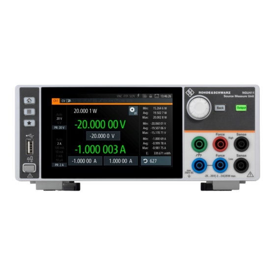
Summary of Contents for Rohde & Schwarz R&S NGU411
- Page 1 ® R&S Source Measure Units Getting Started (;ÝHÛ2) 1179247702 Version 03 Distributed by: Sie haben Fragen oder wünschen eine Beratung? Angebotsanfrage unter +49 7121 / 51 50 50 oder über info@datatec.eu...
- Page 2 ® This manual describes the following R&S NGU models with firmware version 1.00 and higher: ● R&S ® NGU201 2-QUADRANT SMU (3639.3763.02) ● R&S ® NGU401 4-QUADRANT SMU (3639.3763.03) © 2022 Rohde & Schwarz GmbH & Co. KG Muehldorfstr. 15, 81671 Muenchen, Germany Phone: +49 89 41 29 - 0 Email: info@rohde-schwarz.com...
-
Page 3: Table Of Contents
® Contents R&S Contents 1 Safety information..............5 2 Korea certification class A............6 3 Documentation overview............7 3.1 Manuals....................7 3.2 Data sheet....................7 3.3 Calibration certificate................8 3.4 Release notes, open source acknowledgment........8 4 Welcome to R&S NGU............9 5 Putting into operation............10 5.1 Safety.................... - Page 4 ® Contents R&S 8 Maintenance and support........... 26 8.1 Maintenance..................26 8.2 Contacting customer support............26 Index..................28 Getting Started 1179.2477.02 ─ 03...
-
Page 5: Safety Information
® Safety information R&S Safety information The product documentation helps you use the R&S NGU safely and efficiently. Follow the instructions provided here and in the printed "Basic Safety Instruc- tions". Keep the product documentation nearby and offer it to other users. Intended use The R&S NGU is intended for the development, production and verification of electronic components and devices in industrial, administrative, and laboratory... -
Page 6: Korea Certification Class A
® Korea certification class A R&S Korea certification class A 이 기기는 업무용(A급) 전자파 적합기기로서 판매자 또는 사용자는 이 점을 주의하 시기 바라며, 가정외의 지역에서 사용하는 것을 목적으로 합니다. Getting Started 1179.2477.02 ─ 03... -
Page 7: Documentation Overview
® Documentation overview R&S Data sheet Documentation overview This section provides an overview of the R&S NGU user documentation. Manuals You find the documents on the R&S NGU product page at: www.rohde-schwarz.com/manual/ngu Getting started Introduces the R&S NGU source measure units and describes how to set up and start working with the instrument. -
Page 8: Calibration Certificate
® Documentation overview R&S Release notes, open source acknowledgment Calibration certificate The document is available on https://gloris.rohde-schwarz.com/calcert. You need the device ID of your instrument, which you can find on a label on the rear panel. Release notes, open source acknowledgment The release notes list new features, improvements and known issues of the cur- rent firmware version, and describe the firmware installation. -
Page 9: Welcome To R&S Ngu
® Welcome to R&S NGU R&S Welcome to R&S NGU The single source measure units are based on a classical transformer concept with linear regulators. This concept allows the instrument to achieve highest accu- racy and lowest residual ripple. Multi-purpose protection functions are available which you can set separately, such as overcurrent protection (OCP), overvoltage protection (OVP) and over- power protection (OPP). -
Page 10: Putting Into Operation
® Putting into operation R&S Putting into operation This chapter describes how to set up the R&S NGU source measure units for the first time. Risk of injury due to disregarding safety information Observe the information on appropriate operating conditions provided in the data sheet to prevent personal injury or damage to the instrument. - Page 11 ® Putting into operation R&S Risk of instrument damage during operation An unsuitable operating site or test setup can cause damage to the instru- ment and the connected devices. Ensure the following operating conditions before you switch on the instrument: ●...
-
Page 12: Safety
® Putting into operation R&S Safety Safety Recommendations on secure operation The R&S NGU is designed to operate at local workplaces or in secured net- works (LAN). It should not be accessible from the internet, because of a potential security risk, e.g. attackers could misuse or damage your device. Please always install the latest firmware. -
Page 13: Intended Operation
® Putting into operation R&S Intended operation If it is assumed that a safe operation is no longer possible, the instrument must be shut down and secured against any unintended operation. Safe operation can no longer be assumed when: ● Instrument shows visible damage ●... -
Page 14: Unpacking And Checking The Instrument
® Putting into operation R&S Unpacking and checking the instrument The instrument may be operated only under the operating conditions and in the positions specified by the manufacturer, without the product's ventilation being obstructed. If the manufacturer’s specifications are not observed, this can result in electric shock, fire and/or serious personal injury, and in some cases, death. - Page 15 ® Putting into operation R&S Unpacking and checking the instrument ● Check the equipment for completeness using the delivery note and package contents list for the various items. ● Check the instrument for any damage and loose parts. If there is any damage, immediately contact the carrier who delivered the instrument.
-
Page 16: Setting Up The Instrument
® Putting into operation R&S Setting up the instrument Setting up the instrument The R&S NGU is designed for benchtop and rackmount operation. 5.4.1 Bench operation On a benchtop, the R&S NGU source measure unit can either lie flat or stand on its feet. -
Page 17: Instrument Tour
® Instrument tour R&S Overview of controls Instrument tour This chapter provides an overview of all the controls available in the R&S NGU models and steps to switch on the instrument for the first time. ● Overview of controls..................17 ● Switching on the instrument................ - Page 18 ® Instrument tour R&S Overview of controls 5 = Output terminals 6 = Power key 7 = USB connector Menu control keys (1) The menu control keys allow you to access the home window, device/channel menu window and user button key in the instrument. For a detailed description on menu control keys, see section "Menu Controls"...
-
Page 19: Rear Panel
® Instrument tour R&S Overview of controls Both models are equipped with "Force (High)", 2 x "Force (Low)", "Sense (High)", "Sense (Low)" and a ground terminal. With a jumper connecting the ground terminal and the additional "Force (Low)" connector, the R&S NGU provides good ground connection which is essential when measuring very small voltages and currents. - Page 20 ® Instrument tour R&S Overview of controls 12 = Ethernet (LAN) connector 13 = Cover for optional IEEE-488 (GPIB) interface 14 = Digital I/O connector AC inlet with fuse holder and voltage selector (8) Main supply cord Do not use detachable mains supply cord with inadequate rating. The power cable must be plugged in before signal circuits can be connected.
- Page 21 ® Instrument tour R&S Overview of controls USB connectors (10, 11) The USB host connector (Type-A) can be used for mass storage devices like the USB connector at the front panel. The USB device connector is a Type-B connector for remote control operation. Ethernet connector (12) 10/100 Ethernet port for remote control operation via the local area network.
-
Page 22: Switching On The Instrument
® Instrument tour R&S Switching on the instrument Table 6-2: Inhibit signals Signal name Descriptions Inhibit Ch1 Pin 1 of Digital I/O If the inhibit signal goes active, channel 1 connector output is turned off. The inhibit signal is low active (inverted logic). - Page 23 ® Instrument tour R&S Switching on the instrument By default, all output channels are turned off when the instrument is switched on to prevent connected loads from being damaged unintentionally. During startup, the R&S NGU is loaded with the last saved instrument settings from internal memory.
-
Page 24: Trying Out The Instrument
® Trying out the instrument R&S Activating the channel output Trying out the instrument This chapter describes some basic functions that you can perform with the R&S NGU. Source and sink current The R&S NGU201 is a 2 quadrant source measure unit whereas the R&S NGU401 is a 4 quadrant source measure unit. - Page 25 ® Trying out the instrument R&S Activating the channel output To switch on or off channel output. ► Press [Output] key on the front panel. The R&S NGU outputs the set voltage level on the output terminal. Depending on the operating mode which the R&S NGU is operated in, the follow- ing are observed: CR mode CR mode is available only with R&S NGU201 model.
- Page 26 ® Maintenance and support R&S Contacting customer support Maintenance and support Maintenance Regular maintenance improves the life span of the instrument, the following chap- ter provides information on instrument maintenance. Cleaning Before cleaning the instrument, ensure that it has been switched off and the power cable is disconnected.
- Page 27 ® Maintenance and support R&S Contacting customer support Contact information Contact our customer support center at www.rohde-schwarz.com/support, or fol- low this QR code: Figure 8-1: QR code to the Rohde & Schwarz support page Getting Started 1179.2477.02 ─ 03...
- Page 28 ® Index R&S Index Activating the channel output ....24 Putting into operation ......10 Intended operation ......13 Safety ..........12 Unpacking and checking the instrument Calibration certificate ......... 8 ............14 Customer support ........26 Rear panel Data sheet ..........7 AC inlet with fuse holder .....
Need help?
Do you have a question about the R&S NGU411 and is the answer not in the manual?
Questions and answers