Table of Contents
Advertisement
Quick Links
Advertisement
Table of Contents

Related Manuals for Rohde & Schwarz R&S NRX Series


Summary of Contents for Rohde & Schwarz R&S NRX Series
- Page 1 ® R&S Power Meter Getting Started (>HÔÔ2) 1424707002 Version 11...
- Page 2 ® This document describes the following R&S NRX models and options: ● R&S ® NRX (1424.7005K02) ● R&S ® NRX-B1 (1424.7805K02) ● R&S ® NRX-B4 (1424.8901K02) ● R&S ® NRX-B8 (1424.8301K02) ● R&S ® NRX-B9 (1424.8601K02) ● R&S ® NRX-K2 (1424.9208K02) ●...
-
Page 3: Table Of Contents
® Contents R&S Contents 1 Safety and regulatory information........5 1.1 Safety instructions................6 1.2 Labels on the product................9 1.3 Warning messages in the documentation.......... 9 1.4 Korea certification class B..............10 2 Documentation overview............ 11 2.1 Getting started manual............... 11 2.2 User manual..................11 2.3 Instrument security procedures............ - Page 4 ® Contents R&S 4.7.2 Optional interface for R&S NRT-Z sensors (R&S NRX-B9)....20 4.7.3 LAN interface..................21 4.7.4 USB 2.0 host interfaces................ 22 4.8 Connecting USB and external devices..........22 4.9 Switching on or off................22 5 Instrument tour..............24 5.1 Front panel tour..................
-
Page 5: Safety And Regulatory Information
® Safety and regulatory information R&S Safety and regulatory information The product documentation helps you use the product safely and efficiently. Fol- low the instructions provided here and in the following chapters. Intended use <product-specific intended use> Combined with the supported R&S power sensors, the R&S NRX base unit is intended for power measurements in development and production. -
Page 6: Safety Instructions
® Safety and regulatory information R&S Safety instructions Safety instructions Products from the Rohde & Schwarz group of companies are manufactured according to the highest technical standards. To use the products safely, follow the instructions provided here and in the product documentation. Keep the prod- uct documentation nearby and offer it to other users. - Page 7 ® Safety and regulatory information R&S Safety instructions ment. The product is suitable for pollution degree 2 environments where noncon- ductive contamination can occur. For more information on environmental condi- tions such as ambient temperature and humidity, see the specifications docu- ment.
- Page 8 ® Safety and regulatory information R&S Safety instructions does not adjust automatically, set the correct value and check the rating of the fuse. ● Only use the power cable delivered with the product. It complies with country- specific safety requirements. Only insert the plug into an outlet with protective conductor terminal.
-
Page 9: Labels On The Product
® Safety and regulatory information R&S Warning messages in the documentation Labels on the product Labels on the casing inform about: ● Personal safety, see "Meaning of safety labels" on page 8 ● Environment safety, see Table 1-1 ● Identification of the product, see Chapter 5.2.7, "Name plate", on page 31. -
Page 10: Korea Certification Class B
® Safety and regulatory information R&S Korea certification class B Korea certification class B 이 기기는 가정용(B급) 전자파 적합기기로서 주로 가정에서 사용하는 것을 목적으 로 하며, 모든 지역에서 사용할 수 있습니다. Getting Started 1424.7070.02 ─ 11... -
Page 11: Documentation Overview
® Documentation overview R&S Instrument security procedures Documentation overview This section provides an overview of the R&S NRX user documentation. Unless specified otherwise, you find the documents at: www.rohde-schwarz.com/manual/NRX Further documents are available at: www.rohde-schwarz.com/product/NRX Getting started manual Introduces the R&S NRX and describes how to set up and start working with the product. -
Page 12: Printed Safety Instructions
® Documentation overview R&S Release notes and open source acknowledgment (OSA) Printed safety instructions Provides safety information in many languages. The printed document is deliv- ered with the product. Specifications and product brochures The specifications document, also known as the data sheet, contains the techni- cal specifications of the R&S NRX. -
Page 13: Key Features
® Key features R&S Key features The R&S NRX supports: ● Easy RF power measurements ● Multichannel measurements ● RF pulse analysis ● System integration The R&S NRX is a versatile, user-friendly base unit. ● Straightforward numerical and graphical display of measured values, plus intuitive operation with touchscreen-based graphical user interface ●... -
Page 14: Preparing For Use
® Preparing for use R&S Unpacking and checking Preparing for use Here, you can find basic information about setting up the product for the first time. ● Lifting and carrying..................14 ● Unpacking and checking................. 14 ● Choosing the operating site................15 ●... -
Page 15: Choosing The Operating Site
® Preparing for use R&S Setting up the product Choosing the operating site Specific operating conditions ensure proper operation and avoid damage to the product and connected devices. For information on environmental conditions such as ambient temperature and humidity, see the specifications document. For safety information, see "Choosing the operating site"... - Page 16 ® Preparing for use R&S Setting up the product To place the product on a bench top 1. Place the product on a stable, flat and level surface. Ensure that the surface can support the weight of the product. For information on the weight, see the specifications document.
-
Page 17: Mounting The Product In A Rack
® Preparing for use R&S Setting up the product ● Do not place the product next to heat-generating equipment such as radia- tors or other products. 4.4.2 Mounting the product in a rack To prepare the rack 1. Observe the requirements and instructions in "Setting up the product"... -
Page 18: Considerations For Test Setup
® Preparing for use R&S Connecting to power Considerations for test setup Cable selection and electromagnetic interference (EMI) Electromagnetic interference (EMI) can affect the measurement results. To suppress electromagnetic radiation during operation: ● Use high-quality shielded cables, for example, double-shielded RF and LAN cables. -
Page 19: Connecting Sensors
® Preparing for use R&S Connecting sensors The required ratings are listed next to the AC power connector and in the data sheet. Further information: ● Chapter 5.2.5, "AC supply and power switch", on page 30 Connecting sensors The R&S NRX supports a wide range of Rohde & Schwarz power sensors. See the specifications document for detailed information. -
Page 20: Optional Interface For R&S Nrt-Z Sensors (R&S Nrx-B9)
® Preparing for use R&S Connecting sensors Use an R&S NRP‑ZK8 cable cable to connect a sensor to the R&S NRX. If you use an R&S NRP‑ZK6 cable, the reference clock and trigger are not supported. 1. 8-pin female connector of R&S NRP‑ZK8 cable: a) Insert the screw-lock cable connector into the host interface of the sensor. -
Page 21: Lan Interface
® Preparing for use R&S Connecting sensors 1 = Source 2 = Port 1 (RF connector) 3 = R&S NRT‑Zxx sensor 4 = Port 2 (RF connector) 5 = Load 6 = Host interface connector To connect the R&S NRT‑Zxx sensor Connect the R&S NRT‑Zxx sensor between the source and load of your test setup as follows. -
Page 22: Usb 2.0 Host Interfaces
® Preparing for use R&S Switching on or off Suitable for LAN sensors. 4.7.4 USB 2.0 host interfaces Chapter 5.1.6, "USB host interface", on page 28. Suitable for USB power sensors. You can increase the number of connected power sensors by using USB hubs. Connecting USB and external devices Use the USB interfaces to connect USB devices. - Page 23 ® Preparing for use R&S Switching on or off 2. Press the [standby] key. The LED changes to green. The product boots. If the previous session ended regularly, the product uses the settings from the last session. 3. If you want to return to a defined initial state, perform a preset. To shut down the product The product is in the ready state.
-
Page 24: Instrument Tour
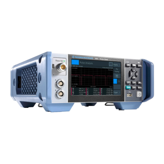
® Instrument tour R&S Front panel tour Instrument tour The meanings of the labels on the product are described in Chapter 1.2, "Labels on the product", on page 9. ● Front panel tour....................24 ● Rear panel tour....................29 Front panel tour Figure 5-1: Front panel of the R&S NRX = Module bay for optional connectors, see Chapter 5.1.2, "Module... -
Page 25: Module Bay
® Instrument tour R&S Front panel tour Sensor connectors A and B are used to connect the R&S NRP power sensors and the R&S NRQ6. For details on the supported power sensors, see the specifi- cations document. The complete functional range, including external trigger and reference clock for the synchronization of connected sensors, is provided by these connectors. -
Page 26: Touchscreen
® Instrument tour R&S Front panel tour To exchange the option 1. Press the latch to the right, using your thumbnail or a small pen. 2. Pull the option from its casing. 3. Insert the other option. 4. Press until you hear a click when the latch locks. Further information: ●... - Page 27 ® Instrument tour R&S Front panel tour [Esc] / Local If you press shortly: ● Changes to the next-higher hierarchy level. ● Escapes from the entry mode in text boxes and lists. ● Closes dialogs without losing any entries that have been made. ●...
-
Page 28: On/Standby Key
® Instrument tour R&S Front panel tour [Zero] Pressing [Zero] opens the "Zeroing Sensors" dialog. If you press [Zero] again, "Zero All Sensors" starts. Also displays status information: ● Zeroing status ● Sensor status [System] Opens the "System Overview" dialog. Cursor keys See (4) in Figure... -
Page 29: Rear Panel Tour
® Instrument tour R&S Rear panel tour Further information: ● Chapter 4.7.4, "USB 2.0 host interfaces", on page 22 ● Chapter 4.8, "Connecting USB and external devices", on page 22 Rear panel tour Figure 5-2: Rear panel of the R&S NRX 1 = Sensor connectors C and D (optional), used to connect R&S power sensors, see Chap- ter 5.2.1, "Sensor connectors C and... -
Page 30: Trig In / Out 2 And Out 1 / Trig Out Connectors
® Instrument tour R&S Rear panel tour For more details, see Chapter 5.1.1, "Sensor connectors A and B", on page 24. 5.2.2 Trig In / Out 2 and Out 1 / Trig Out connectors See (2) in Figure 5-2. The Out 1 / Trig Out BNC connectors supply an analog signal with a voltage between 0 V and 2.5 V. -
Page 31: Iec 625/Ieee 488 Interface
® Instrument tour R&S Rear panel tour The power supply does not have a replaceable fuse. If the product is connected to the mains but cannot be started, contact Rohde & Schwarz customer service for troubleshooting help. Further information: ● Chapter 4.6, "Connecting to power", on page 18... - Page 32 ® Instrument tour R&S Rear panel tour ID: 1424.7005K02 - 100758 - pw POWER METER Figure 5-3: Name plate The name plate also shows the parts of the default hostname. The default host- name consists of <type>-<serial number>. For the R&S NRX with the name plate shown in Figure 5-3, the default hostname NRX-100758...
-
Page 33: Contacting Customer Support
® Contacting customer support R&S Contacting customer support Technical support – where and when you need it For quick, expert help with any Rohde & Schwarz product, contact our customer support center. A team of highly qualified engineers provides support and works with you to find a solution to your query on any aspect of the operation, program- ming or applications of Rohde &... -
Page 34: Index
® Index R&S Index Symbols Front panel ..........24 Keys ............ 26 1 Trig key ..........27 Getting started ......... 11 AC power supply ........30 Connecting to ........18 Hardware option ........25 Help ............11 Bench top operation ........ 15 Hostname Brochures .......... - Page 35 ® Index R&S Open source acknowledgment ....12 Operating Zero key ..........28 Conditions ........... 15 Site ............15 OSA ............12 Out 1 / Trig Out connector ....... 30 Power supply Connecting to ........18 Preparing for use ........14 Preset key ..........27 Rack mounting ........
Need help?
Do you have a question about the R&S NRX Series and is the answer not in the manual?
Questions and answers