Lippert Components IN-WALL Slide-out Service Manual
Hide thumbs
Also See for IN-WALL Slide-out:
- Troubleshooting manual (11 pages) ,
- Assembly manual (6 pages)

Related Manuals for Lippert Components IN-WALL Slide-out


Summary of Contents for Lippert Components IN-WALL Slide-out
- Page 1 IN-WALL Slide-out SERVICE MANUAL ® Page 1 Rev: 06.14.2016 IN-WALL® Slide-out Service Manual...
-
Page 2: Table Of Contents
TABLE OF CONTENTS Safety Information Operation Prior to Operation Extending Slide-out Room Retracting Slide-out Room Controller Overview (B Version) Controller Overview (C2 Version) Motor and Controller Compatibility Motors and Harnesses Resynchronizing the Slide-out Motors Extend and Retract Switch Connections Power and Ground Connections at the Controller Visual Inspections Measurements Floor Rollers... -
Page 3: Safety Information
Safety Information Failure to act in accordance with the following may result in death, serious injury, coach or property damage. The IN-WALL® Slide-out System is intended for the sole purpose of extending and retracting the slide-out room. Its function should not be used for any purpose or reason other than to actuate the slide-out room. To use the system for any reason other than what it is designed for may result in death, serious injury or damage to the coach. -
Page 4: Extending Slide-Out Room
Extending Slide-out Room Level the unit. NOTe: In the case of a motorized unit, ignition MUST be off to operate the slide-out. Remove the transit bars (if so equipped). Press and hold the IN/OUT switch (Fig. 1B) in the OUT position until the room is fully extended and stops moving. -
Page 5: Controller Overview (B Version)
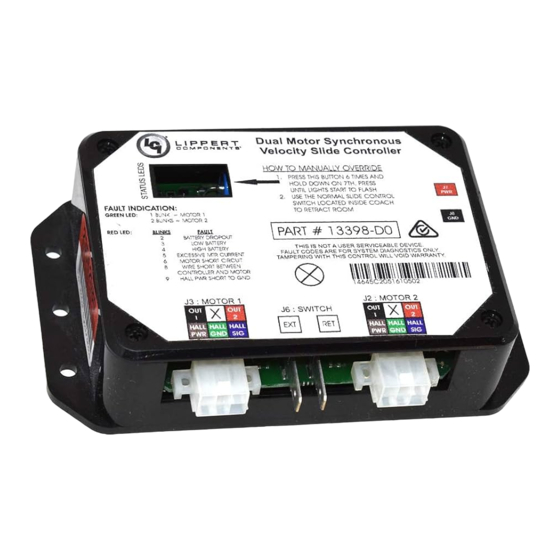
Controller Overview (B Version) Controller Version Mode Button Fig. 2 Green LeD Red LeD Power Connection Motor 2 Connector Motor 1 Connector Switch Connection Fig. 3 - Controller Connections Fig. 4 - Motor Harness Status LeDs: 2 LEDs, 1 green and 1 red, are provided to indicate current controller status and faults. Power Connection: 12V DC input. -
Page 6: Controller Overview (C2 Version)
Controller Overview (C2 Version) Controller Version Mode Button Fig. 5 Green LeD Red LeD Power Connection Switch Connection Motor 2 Connector Motor 1 Connector Fig. 6 - Controller Connections Fig. 7 - Motor Harness Status LeDs: 2 LEDs, 1 green and 1 red, are provided to indicate current controller status and faults. Mode Button: Used to engage the electronic manual override. -
Page 7: Motor And Controller Compatibility
Motor and Controller Compatibility Controller Part # Controller Version Motor(s) Used Replacement Round-Square (Fig. 14), Round- 239657 A (Daisy Chain) (Fig. 8) A Only Round (Fig. 15A) B (Fig. 9) B/C2* Only Round Square (Fig. 14) C (Fig. 10) C/C2* Only 211852 Round-Round (Fig. -
Page 8: Motors And Harnesses
Motors and Harnesses Check for proper connections between the motors and harnesses (Fig. 17). Visually inspect the exposed harnesses to ensure they are not pinched or damaged. NOTe: Ribs on motor connector line up with notch inside of female connector on wiring harness. Color codes on wires also match (black to black, red to red, etc.) Fig. -
Page 9: Visual Inspections
Visual Inspections Measurements Measure from the outside edge of the column to the face of the gear rack (Fig. 18 and 19). The standard measurement should be 2 " plus or minus ". Take this measurement when the room is fully extended and again when the room is 3"... -
Page 10: Floor Rollers
Floor Rollers Check that the seals are not getting caught in the rollers, which could cause binding of the slide-out. Check for proper roller engagement (Fig. 20): A. Rollers should not be digging into the floor of the slide-out. B. Rollers should not spin freely beneath slide-out. Fig. -
Page 11: Troubleshooting
Troubleshooting Checking Circuit Breakers The IN-WALL® Slide-out requires a minimum of a 30-amp circuit breaker. Check the 12-volt circuit breaker box for blown circuit breakers, and replace any if necessary. Consult the RV manufacturer's documentation for the location of the 12-volt circuit breaker box, and the location of the IN-WALL® Slide-out controller’s circuit breaker. If the circuit breaker blows immediately upon replacement, there is a problem with the wiring to the IN-WALL®... -
Page 12: Electronic Manual Override (Controllers C-1 And C-2 Only)
Electronic Manual Override (Controllers C-1 and C-2 Only) NOTe: See (Fig. 24) for locations of the mode button and LEDs. Press the mode button on the controller six times and hold on the seventh for five seconds to enter electronic manual override mode. Use the extend/retract switch to move both motors in or out. -
Page 13: Rewiring Instructions
Rewiring Instructions If it is necessary to replace a malfunctioning Rev. B, C, or C1 controller, it is recommended that the customer do so with a new Rev. C2 controller. In order to properly rewire a Rev. B, C, or C1 controller to a new Rev. C2 controller, the customer will need two new motor harnesses (one for each motor.) Additionally, it will be necessary to modify the power wire from the controller to the extend/retract switch by adapting the wire to piggyback the connection at the power junction. -
Page 14: Motor Replacement
Motor Replacement Tools Required • Drill or cordless screw gun • Fast-bonding adhesive With Motor Notch (Current Style) NOTe: There MUST be access to both the interior and exterior of the coach to perform this procedure. Extend the slide-out to halfway out of the coach. On the exterior, slide the bulb seal down to access the motor retention screw (Fig. - Page 15 Pull motor up and tip the bottom of the motor Slide Room out of the notch to remove it (Fig. 28). Inside Wall Fig. 28 Place new motor into the H-column, making of Coach sure that the wiring is facing the back of the H-Column.
-
Page 16: Without Motor Notch (Old Style)
Without Motor Notch (Old Style) NOTe: There MUST be access to both the interior and exterior of the coach to perform this procedure. Extend the slide-out to halfway out of the coach. Adequately support the slide room, but do not lift it. From the exterior, slide the bulb seal down to access the motor retention screw (Fig. - Page 17 From the inside of the unit, push the slide-out Fig. 33 Slide Room out until the top of the H-column is accessible Outside Wall (Fig. 33). of Coach Pull the motor up and out of the H-column (Fig. 34). Place new motor into the H-column, making sure that the wiring is facing the back of the H-Column.
-
Page 18: Assembly Removal Procedure
Assembly Removal Procedure Tools Required • Electric drill or cordless screw gun • Rubber mallet Fig. 37 • 2x4 (length=gap between T-molding and side of unit-1/4”) • Razor knife • Floor jack Procedure NOTe: If the slide will not move by use of the switch it may be necessary to use one of the three methods (A, B, or C) described below: A. - Page 19 11. Remove all screws from the gear racks (Fig. 40). Fig. 40 Slide Room Upper Gear Rack #10 Pan Head Screws 12. You may need to pry the gear racks away from the sides of the slide room with a flathead screwdriver or putty knife.
-
Page 20: Assembly Installation Procedure
Assembly Installation Procedure Prepare the slide room and side of the unit for the new install by cleaning the surfaces of any adhesive residue using a putty knife and a solvent, being careful not to damage the finishes on the unit. Prepare the new system for installation: measure the distance (center to center) from one gear rack to the next gear rack along the slide column. -
Page 21: Synchronizing The Slide-Out Motors
Measure from the bottom gear rack (center to center) Fig. 42 to the next gear rack and align that rack so that it matches the measurement you took off of the system during step 2. This will ensure that the racks are installed parallel and square. -
Page 22: In-Wall® Slide-Out Assembly
IN-WALL SLIDE-OUT ASSEMBLY ® SLIDe-OUTS Upper Bearing Block Detail Motor Upper Gear Rack Upper Bearing Block Gear Rack Shoe H-Column V-Roller Torque Shaft Lower Bearing Block Detail Torque Shaft Lower Bearing Block Gear Rack Spur Gear Lower Gear Rack Shoe V-Roller Page 22 Rev: 06.14.2016... -
Page 23: In-Wall® Slide-Out Controllers
IN-WALL SLIDE-OUT CONTROLLERS ® SLIDe-OUTS Rev B Rev C-1 Rev C-2 8 Amp Part # Description 211852 - Rev B, Rev C-1, Rev C-2 Dual Motor Synchronous Velocity Slide Controller NOTe: Rev. B and C-1 are no longer available from LCI. Replace with Rev. C-2. Dual Motor Synchronous Velocity Slide Controller 326876 - 8 amp NOTe: This controller will not replace other controller versions. -
Page 24: In-Wall® Slide-Out Motors
IN-WALL SLIDE-OUT MOTORS ® SLIDe-OUTS Callout Part # Description 229466 Motor 287298 Motor, High Torque 500:1 236575 Motor, 300:1 Obsolete (Replace with 236575) Page 24 Rev: 06.14.2016 IN-WALL® Slide-out Service Manual... -
Page 25: In-Wall® Slide-Out Components
IN-WALL SLIDE-OUT COMPONENTS ® SLIDe-OUTS Callout Part # Description 238744 5 ft. Controller to Motor Harness 238990 10 ft. Controller to Motor Harness 247768 15 ft. Controller to Motor Harness 229755 20 ft. Controller to Motor Harness 238991 25 ft. Controller to Motor Harness 229756 30 ft. - Page 26 IN-WALL SLIDE-OUT COMPONENTS ® SLIDe-OUTS Callout Part # Description *See Note Upper Gear Rack *See Note Lower Gear Rack *See Note Lower Bearing Block *See Note Upper Bearing Block *See Note Lower Bearing Block (Hex Shaft) *See Note Upper Bearing Block (Hex Shaft) *See Note Lower Bearing Block (Inverted) *See Note...
- Page 27 IN-WALL SLIDE-OUT COMPONENTS ® SLIDe-OUTS Callout Part # Description *See Note Aluminum Torque Shaft *See Note Steel Torque Shaft *See Note Hex Torque Shaft 238461 Coupler - Old Style (for 229466 Motor) 238461 Coupler - New Style (for 236575 Motor) 285083 Hex Coupler 238893...
- Page 28 IN-WALL SLIDE-OUT COMPONENTS ® SLIDe-OUTS Callout Part # Description Measurements 156603 Seal 1" x 2 21/32" x 5/64" 132733 Sweep Seal 2 43/64" x 1/16" 239667 EK Design Flap 11/4" 240410 Flat Side Wiper 1 1/4" 240448 KE Black Single Wiper with Leg 1 1/4"...
- Page 29 The contents of this manual are proprietary and copyright protected by Lippert Components, Inc. (“LCI”). LCI prohibits the copying or dissemination of portions of this manual unless prior written consent from an authorized LCI representative has been provided. Any unauthorized use shall void any applicable warranty. ...
Need help?
Do you have a question about the IN-WALL Slide-out and is the answer not in the manual?
Questions and answers