Lippert Components Above Floor Slide-out Installation Manual
Hide thumbs
Also See for Above Floor Slide-out:
- Operation and service manual (12 pages) ,
- Oem installation manual (16 pages)
Table of Contents
Advertisement
Advertisement
Table of Contents
Troubleshooting

Related Manuals for Lippert Components Above Floor Slide-out


Summary of Contents for Lippert Components Above Floor Slide-out
- Page 1 Above Floor Slide-out (PG) OEM INSTALLATION MANUAL...
-
Page 2: Table Of Contents
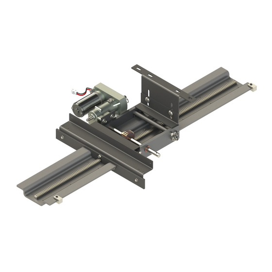
Notes System Information The Above Floor Slide-out System is a rack and pinion style slide system. Utilizing a bi-directional electric motor to actuate the drive shaft, the slide-out room is extended and retracted from the same source. The actuator has a built-in automatic clutching feature. There are no serviceable parts within the electric motor. -
Page 3: Safety Information
Moving parts can pinch, crush or cut. Keep clear and use caution. The Above Floor Slide-out system is intended for the sole purpose of extending and retracting the slide-out room. Its function should not be used for any other purpose or reason than to actuate the slide-out room. -
Page 4: Installation
Installation Prior to installation, Inspect slide-out mechanism and ensure that all stop blocks are intact and that there are no missing/damaged parts. Installing Slide-Out Assembly onto Slide Opening Locate the slide-out assembly or assemblies as per OEM design. For a single assembly, center the slide- out assembly in the slide-out opening. -
Page 5: Room Adjustment
Room Adjustment For vertical adjustment, do as follows: Loosen the two carriage bolts (Fig. 3A) just enough to release tension on the interior mounting plate (Fig. 3B). Adjust the room to desired location. Tighten the two carriage bolts before operating room. Fig. -
Page 6: Slide Room Installation
Slide Room Installation Place room on top of the hat channel(s) (Fig. 5). Center the room in the slide opening. NOTE: Ensure the room is centered before securing to hat channel(s). Locate the two exterior holes (Fig. 5A) in the hat channel. Secure the room to the hat channel(s) using OEM supplied fasteners. -
Page 7: Hard Stops
Hard stops are added to the above floor slide-out systems in the form of stop block assemblies (Fig. 7A). The stop block assemblies are provided as a clamp-on stop, giving the slide-out the hard stops it needs to end the extend and retract travel of the slide out mechanism. -
Page 8: Operation
Moving parts can pinch, crush or cut. Keep clear and use caution. Prior to Operation Prior to operating the above floor slide-out, do as follows: Unit should be parked on the most level surface available. If operating a motorized coach the PARKING BRAKE must be engaged. -
Page 9: Extending Slide-Out Room
Extending Slide-Out Room Ensure the battery is fully charged and hooked up to the electrical system. If using a switch to activate the slide-out room, press and hold the IN/OUT switch in the OUT (Fig. 9B) position until room is fully extended and stops moving. NOTE: Only hold OUT switch until room stops. -
Page 10: Troubleshooting
Troubleshooting When something restricts room travel, system performances will be unpredictable. It is very important that slide rails, rack and pinion be free of any form of debris or other type of contamination and allowed to travel freely the full distance or “STROKE.” Debris build-up during travel is an example of the type of contamination that may occur. -
Page 11: Troubleshooting Chart
Troubleshooting Chart Use the Troubleshooting Chart as necessary to assist in the identification and resolution of other possible post-installation concerns. What Is Happening? Why? What Should Be Done? Restriction or obstruction inside or Check for and clear obstruction. outside of unit. Check battery voltage and charge if Room doesn't move needed. -
Page 12: Manual Override
Manual Override Do not work on the slide-out system unless the battery is disconnected. Failure to disconnect the battery may result in death or serious personal injury. Always disconnect battery from system prior to manually operating the system. Failure to disconnect the battery can cause electricity to backfeed through the motor and cause serious damage to the system as well as void the warranty. - Page 13 Disconnect the motor leads. With your thumb, depress the brake release lever on the side of the rubber boot cover (Fig. 11A). Then, rotate the brake release lever counter-clockwise to release the motor brake (Fig. 12A). NOTE: Do NOT remove rubber boot cover. Removal of rubber boot cover will void manufacturer’s warranty. Locate the manual "...
-
Page 14: Wiring Diagram
Wiring Diagram NOTE: Make sure the OEM-supplied heat 10 AWG Minimum shrink butt connectors are appropriate for the gauge of wire used. Battery OEM-Supplied Circuit Protection Black per RVIA Standards Switch Motor Yellow Green Black Heat Shrink Butt Connector Page 14 Rev: 01.11.19 CCD-0001470... -
Page 15: Notes
Notes Page 15 Rev: 01.11.19 CCD-0001470... - Page 16 The contents of this manual are proprietary and copyright protected by Lippert Components, Inc. (“LCI”). LCI prohibits the copying or dissemination of portions of this manual unless prior written consent from an authorized LCI representative has been provided. Any unauthorized use shall void any applicable warranty. ...
Need help?
Do you have a question about the Above Floor Slide-out and is the answer not in the manual?
Questions and answers