Table of Contents
Advertisement
Available languages
Available languages
Quick Links
LOV TO ELECTRIC S.P. .
24020 GORLE (BERGAMO) ITALIA
VIA DON E. MAZZA, 12
TEL. 035 4282111
L
E
E-mail info@
ovato
lectric.com
L
E
Web
www.
ovato
lectric.com
W RNING!
– Carefully read the manual before the installation or use.
– This equipment is to be installed by qualified personnel, complying to current standards, to avoid
damages or safety hazards.
– Before any maintenance operation on the device, remove all the voltages from measuring and supply inputs and short-
circuit the CT input terminals.
– The manufacturer cannot be held responsible for electrical safety in case of improper use of the equipment.
– Products illustrated herein are subject to alteration and changes without prior notice. Technical data and descriptions
in the documentation are accurate, to the best of our knowledge, but no liabilities for errors, omissions or
contingencies arising there from are accepted.
– A circuit breaker must be included in the electrical installation of the building. It must be installed close by the
equipment and within easy reach of the operator. It must be marked as the disconnecting device of the equipment:
IEC /EN 61010-1 § 6.11.3.1.
– Clean the device with a soft dry cloth; do not use abrasives, liquid detergents or solvents.
TTENTION !
– Lire attentivement le manuel avant toute utilisation et installation.
– Ces appareils doivent être installés par un personnel qualifié, conformément aux normes en vigueur en
matière d'installations, afin d'éviter de causer des dommages à des personnes ou choses.
– Avant toute intervention sur l'instrument, mettre les entrées de mesure et d'alimentation hors tension et court-circuiter
les transformateurs de courant.
– Le constructeur n'assume aucune responsabilité quant à la sécurité électrique en cas d'utilisation impropre du
dispositif.
– Les produits décrits dans ce document sont susceptibles d'évoluer ou de subir des modifications à n'importe quel
moment. Les descriptions et caractéristiques techniques du catalogue ne peuvent donc avoir aucune valeur
contractuelle.
– Un interrupteur ou disjoncteur doit être inclus dans l'installation électrique du bâtiment. Celui-ci doit se trouver tout
près de l'appareil et l'opérateur doit pouvoir y accéder facilement. Il doit être marqué comme le dispositif
d'interruption de l'appareil : IEC/ EN 61010-1 § 6.11.3.1.
– Nettoyer l'appareil avec un chiffon doux, ne pas utiliser de produits abrasifs, détergents liquides ou solvants.
CHTUNG!
– Dieses Handbuch vor Gebrauch und Installation aufmerksam lesen.
– Zur Vermeidung von Personen- und Sachschäden dürfen diese Geräte nur von qualifiziertem
Fachpersonal und unter Befolgung der einschlägigen Vorschriften installiert werden.
– Vor jedem Eingriff am Instrument die Spannungszufuhr zu den Messeingängen trennen und die Stromwandler
kurzschlie en.
– Bei zweckwidrigem Gebrauch der Vorrichtung übernimmt der Hersteller keine Haftung für die elektrische Sicherheit.
– Die in dieser Broschüre beschriebenen Produkte können jederzeit weiterentwickelt und geändert werden. Die im
Katalog enthaltenen Beschreibungen und Daten sind daher unverbindlich und ohne Gewähr.
– In die elektrische Anlage des Gebäudes ist ein Ausschalter oder Trennschalter einzubauen. Dieser muss sich in
unmittelbarer Nähe des Geräts befinden und vom Bediener leicht zugänglich sein. Er muss als Trennvorrichtung für das
Gerät gekennzeichnet sein: IEC/ EN 61010-1 § 6.11.3.1.
– Das Gerät mit einem weichen Tuch reinigen, keine Scheuermittel, Flüssigreiniger oder Lösungsmittel verwenden.
DVERTENCI
– Leer atentamente el manual antes de instalar y utilizar el regulador.
– Este dispositivo debe ser instalado por personal cualificado conforme a la normativa de instalación
vigente a fin de evitar daños personales o materiales.
– Antes de realizar cualquier operación en el dispositivo, desconectar la corriente de las entradas de alimentación y
medida, y cortocircuitar los transformadores de corriente.
– El fabricante no se responsabilizará de la seguridad eléctrica en caso de que el dispositivo no se utilice de forma
adecuada.
– Los productos descritos en este documento se pueden actualizar o modificar en cualquier momento. Por consiguiente,
las descripciones y los datos técnicos aquí contenidos no tienen valor contractual.
– La instalación eléctrica del edificio debe disponer de un interruptor o disyuntor. Éste debe encontrarse cerca del
dispositivo, en un lugar al que el usuario pueda acceder con facilidad. Además, debe llevar el mismo marcado que el
interruptor del dispositivo (IEC/ EN 61010-1 § 6.11.3.1).
– Limpiar el dispositivo con un trapo suave; no utilizar productos abrasivos, detergentes líquidos ni disolventes.
UPOZORNĚNÍ
AVERTIZARE!
GB
THYRISTOR MODULES
Instruction manual
DCTL...
TTENZIONE!
– Leggere attentamente il manuale prima dell'utilizzo e l'installazione.
– Questi apparecchi devono essere installati da personale qualificato, nel rispetto delle vigenti normative
impiantistiche, allo scopo di evitare danni a persone o cose.
– Prima di qualsiasi intervento sullo strumento, togliere tensione dagli ingressi di misura e di alimentazione e
cortocircuitare i trasformatori di corrente.
– Il costruttore non si assume responsabilità in merito alla sicurezza elettrica in caso di utilizzo improprio del dispositivo.
– I prodotti descritti in questo documento sono suscettibili in qualsiasi momento di evoluzioni o di modifiche. Le
descrizioni ed i dati a catalogo non possono pertanto avere alcun valore contrattuale.
– Un interruttore o disgiuntore va compreso nell'impianto elettrico dell'edificio. Esso deve trovarsi in stretta vicinanza
dell'apparecchio ed essere facilmente raggiungibile da parte dell'operatore. Deve essere marchiato come il dispositivo
di interruzione dell'apparecchio: IEC/ EN 61010-1 § 6.11.3.1.
– Pulire l'apparecchio con panno morbido, non usare prodotti abrasivi, detergenti liquidi o solventi.
UW G !
ПРЕДУПРЕЖДЕНИЕ!
DİKKAT!
G
B
1
Advertisement
Chapters
Table of Contents

Related Manuals for LOVATO ELECTRIC DCTL Series


Summary of Contents for LOVATO ELECTRIC DCTL Series
- Page 1 THYRISTOR MODULES Instruction manual LOV TO ELECTRIC S.P. . 24020 GORLE (BERGAMO) ITALIA VIA DON E. MAZZA, 12 TEL. 035 4282111 E-mail info@ ovato lectric.com www. ovato lectric.com DCTL... W RNING! TTENZIONE! – Carefully read the manual before the installation or use. –...
-
Page 2: Table Of Contents
INTRODUCTION The DCTL series of thyristor modules is intended to be used in power factor correction panels where a fast compensation is required due to a very fast variation of the inductive load. They are normally controlled by a fast power factor controller like LOVATO DCRG8-DCRG 8F series controllers, even though they are compatible with any type of fast compensation controller. -
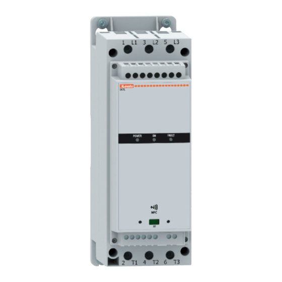
Page 3: Front Status Leds
PARAMETER SETTING FROM PC – With the Lovato Electric Xpress remote control and configuration software is possible to read and modify the parameters of DCTL and save them on a file on the hard disk of the PC, or alternatively you can upload a parameters file from the PC and download it into the DCTL thyristor module. -
Page 4: Parameter Table
PARAMETERS TABLE – The available sub-menus are shown in the following table: Code MENU DESCRIPTION GENERAL Capacitor bank characteristics PROTECTIONS Protections thresholds configuration PASSWORD Password management M01 – GENERAL Cod. Description Default Range P01.01 Capacitor bank rated power kvar (DCTL power size) 50..120% of DCTL power 7.5 kvar 9.0 kvar... -
Page 5: Alarms
ALARMS – When an alarm occurs, the red FAULT LED on the front panel will blink for as long as an alarm is active. The number of flashes identifies the type of active alarm (e.g. 1 flash = A01 alarm, 2 flashes = A02 alarm, 3 flahses = A03 alarm, etc..). -
Page 6: Recommendations
RECOMMENDATIONS – Switch off power to the thyristor module every time you need to work on the electrical or mechanical equipment of the system or machine. – A disconnecting device, such as switch disconnector, line contactor, etc. must always be included to cut off the power supply. –... - Page 7 Command with dry contact Moduli a tiristori DCTL Tyristor module DCTL Induttori raccomandati Recommended inductors Command via RS485 serial communication from DCRG 8F controller REQUIREMENTS – The DCRG 8F controller must be equipped with the optional RS485 communication module code EXP10 12 –...
-
Page 8: Mechanical Dimensions
MECHANICAL DIMENSIONS[mm] SIZE 1: SIZE 2: DCTLA 400 0075 - DCTLA 400 0150 - DCTLA 400 0300 DCTLA 400 0500 - DCTLA 480 0600 - DCTLA 690 0300 - DCTLA 690 0500 DCTLA 480 0090 - DCTLA 480 0180 - DCTLA 480 0360 171.5 Ø5.40 Ø5.40... -
Page 9: Terminal Layout
TERMINAL LAYOUT A1 A2 11 14 12 CONTROL C IN1 NTC NTC POWER RATINGS Code DCTL DCTL DCTL DCTL DCTL DCTL DCTL DCTL DCTL DCTL DCTL DCTL DCTL 0075 0150 0300 0500 1000 0090 0180 0360 0600 1200 0300 0500 1000 Rated operating voltage Us 400VAC 50/60Hz... -
Page 10: Technical Characteristics
Input signal delay 1xAWG3/0 (for cULus compliance you must install NTC probe input: terminals NTC - NTC n°2 lugs kit code EXA01 Type of sensor NTC (LOVATO Electric code NTC01) + n°2 terminal shrouds kit code EXA 02) Measuring range -25...+85°C Imprint... - Page 11 MÓDULOS DE TIRISTOR Manual de instrucciones LOV TO ELECTRIC S.P. . 24020 GORLE (BERGAMO) ITALIA VIA DON E. MAZZA, 12 TEL. 035 4282111 E-mail info@ ovato lectric.com www. ovato lectric.com DCTL... W RNING! TTENZIONE! – Carefully read the manual before the installation or use. –...
-
Page 12: Introducción
Los módulos de tiristor de la serie DCTL no requieren ninguna programación especial cuando se utilizan las características estándar. Para activar las funciones especiales, como la configuración de protección personalizada, podrá utilizarse el puerto óptico de infrarrojos integrado o la conectividad NFC con los mismos instrumentos de software y hardware que se emplean en otros dispositivos de LOVATO Electric (conectores CX 01/CX 02, software Xpress, App LOVATO SAM1 o App LOVATO NFC). -
Page 13: Led De Estado Frontales
CONFIGURACIÓN DE PARÁMETROS MEDIANTE UN PC – Con el software de configuración y control remoto Lovato Electric Xpress es posible leer y modificar los parámetros del DCTL, así como guardar estos parámetros en un archivo del disco del PC o descargar los parámetros almacenados en el archivo del PC en el DCTL. -
Page 14: Tabla De Parámetros
TABLA DE PARÁMETROS – En la tabla siguiente figura la lista de menús disponibles: Cód. MENÚ DESCRIPCIÓN GENERAL Características de la batería de condensadores PROTECCIÓN Configuración de umbrales de protección CONTRASEÑA Gestión de la contraseña M01 – GENERAL Cód. Descripción Predet. -
Page 15: Alarmas
ALARMAS – Cuando se activa una alarma, el LED rojo FAULT del frontal parpadea hasta que la alarma se activa. El número de parpadeos permite identificar el tipo de alarma activa (por ej., 1 parpadeo = alarma A01, 2 parpadeos = alarma A02 y así sucesivamente). El significado de la alarma se describe en las tablas siguientes. –... -
Page 16: Recomendaciones
RECOMENDACIONES – Cortar la corriente de los módulos de tiristor siempre que sea necesario actuar en la parte eléctrica o mecánica de la máquina o sistema. – Contemplar siempre un dispositivo de interrupción de la alimentación de potencia (seccionador, disyuntor de línea, etc.). –... - Page 17 Control con contacto no alimentado Modulos de tiristor DCTL Moduli a tiristori DCTL Tyristor module DCTL Tyristor module DCTL Inductores recomendados Induttori raccomandati Recommended inductors Recommended inductors Control por comunicaciones serie RS485 del regulador automático DCRG8F REQUISITOS – El regulador DCRG 8F debe contar con el módulo de comunicación RS485 opcional con código EXP10 12. –...
-
Page 18: Dimensiones Mecánicas
DIMENSIONES MECÁNICAS [mm] TAMAÑO 1: TAMAÑO 2: DCTLA 400 0075 - DCTLA 400 0150 - DCTLA 400 0300 DCTLA 400 0500 - DCTLA 480 0600 - DCTLA 690 0300 - DCTLA 690 0500 DCTLA 480 0090 - DCTLA 480 0180 - DCTLA 480 0360 171.5 Ø5.40 Ø5.40... -
Page 19: Disposición De Los Terminales
DISPOSICIÓN DE LOS TERMINALES A1 A2 11 14 12 CONTROL C IN1 NTC NTC POTENCIA NOMINAL Código DCTL DCTL DCTL DCTL DCTL DCTL DCTL DCTL DCTL DCTL DCTL DCTL DCTL 0075 0150 0300 0500 1000 0090 0180 0360 0600 1200 0300 0500 1000... -
Page 20: Características Técnicas
Entrada de sonda NTC: terminales NTC-NTC el kit de terminales n°2 cód. EXA 01 Tipo de sensor NTC (código de LOVATO Electric NTC01) + kit de protección de terminales n°2 kit cód. EXA 02) Rango de medida -25 a +85°C...
Need help?
Do you have a question about the DCTL Series and is the answer not in the manual?
Questions and answers