Advertisement
LOVATO ELECTRIC S.P.A.
24020 GORLE (BERGAMO) ITALIA
VIA DON E. MAZZA, 12
TEL. 035 4282111
FAX (Nazionale): 035 4282200
FAX (International): +39 035 4282400
L
E
E-mail info@
ovato
lectric.com
L
E
Web
www.
ovato
lectric.com
WARNING!
– Carefully read the manual before the installation or use.
– This equipment is to be installed by qualified personnel, complying to current standards, to avoid
damages or safety hazards.
– Remove the dangerous voltage from the product before any maintenance operation on it.
– The manufacturer cannot be held responsible for electrical safety in case of improper use of the
equipment.
– Products illustrated herein are subject to alteration and changes without prior notice. Technical data
and descriptions in the documentation are accurate, to the best of our knowledge, but no liabilities for
errors, omissions or contingencies arising therefrom are accepted.
– Clean the instrument with a soft dry cloth, do not use abrasives, liquid detergents or solvents.
INTRODUCTION
The EXP units for Lovato Electric plug in expandable products are designed and developed to enhance
the functions of connectivity, I/O, memory and analysis of the instrument to which it is connected.
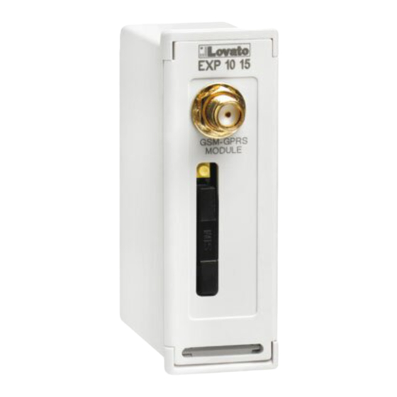
The EXP10 15 implements the GSM-GPRS modem function. This module can be connected to a Lovato
Electric device equipped with EXP slot. The module connection will be done simply by plugging it in to
the expansion slot of the base device. At the power on of the system, the instrument will automatically
recognize the units and the EXP parameters setup will be done directly from the proper instrument menu
in an easy way.
DESCRIPTION
– Compact size
– Direct plug in on the base instrument
– Quadri-band GSM-GPRS modem, suitable for use in with worldwide networks
– Supported functionality:
• Online connection (CSD)
• SMS sending of alarms / status / events
• SMS commands management
• Email sending
• Data and event sending to remote file through FTP server
– Power supply from expansion bus.
– Initialization procedure not necessary.
– Viewing on the main unit display of: GSM network connection status, signal quality, diagnostic and
status messages.
– Built-in SIM card holder.
– SMA connector for anti-vandal, IP65 quad-band outdoor antenna (Lovato code CX03).
LOVATO PRODUCTS COMPATIBILITY
EXP10 15 module can be connected to a Lovato Electric product fitted by EXP receptacle slot. Verify the
compatibility with base unit and possible position in expansion bus with the following table:
BASE DEVICE
BASE DEVICE
FW REVISION
≥ 04
RGK800 / RGK800SA
≥ 00
RGK900 / RGK900SA
≥ 04
DCRG8
≥ 08
DMG900
GB EXPANSION MODULE GSM-GPRS MODEM
Instructions manual
I
MODULO DI ESPANSIONE MODEM GSM-GPRS
Manuale operativo
EXP10 15
POSSIBLE SLOT POSITION
1
2
3
4
G
n.a.
G
G
G
ATTENZIONE!!
– Leggere attentamente il manuale prima dell'utilizzo e l'installazione.
– Questi apparecchi devono essere installati da personale qualificato, nel rispetto delle vigenti normative
impiantistiche, allo scopo di evitare danni a persone o cose.
– Prima di qualsiasi intervento sull'apparecchio, togliere tensione dagli ingressi di alimentazione e dalle
uscite relè dove presenti.
– Il costruttore non si assume responsabilità in merito alla sicurezza elettrica in caso di utilizzo
improprio del dispositivo.
– I prodotti descritti in questo documento sono suscettibili in qualsiasi momento di evoluzioni o di
modifiche. Le descrizioni ed i dati a catalogo non possono pertanto avere alcun valore contrattuale.
– Pulire lo strumento con panno morbido, non usare prodotti abrasivi, detergenti liquidi o solventi.
INTRODUZIONE
I moduli di espansione EXP sono stati progettati e sviluppati per potenziare le funzioni di connettività, I/O,
memorizzazione ed analisi dello strumento base a cui vengono collegati. In particolare il modulo EXP10
15 realizza la funzione di modem GSM-GPRS. Questo modulo è compatibile con un apparecchio Lovato
Electric provvisto di slot per EXP. La connessione avverrà semplicemente inserendo il modulo di
espansione nel dispositivo principale il quale effettuerà automaticamente il riconoscimento.
L'impostazione dei parametri del modulo viene svolta in modo intuitivo e semplice nel menù di
configurazione presente nel dispositivo principale.
DESCRIZIONE
– Dimensioni compatte
– Inserimento diretto nello slot di espansione dell'apparecchio
– Modem GSM-GPRS quadri-band, adatto al funzionamento in tutte le aree geografiche del mondo
– Funzionalità supportate:
• Connessione online (CSD)
• Invio SMS con allarmi / stati / eventi
• Ricezione di comandi da SMS
• Invio e-mail
• Invio dati ed eventi su file remoto tramite server FTP
– Alimentazione tramite bus di espansione
– Nessuna procedura di inizializzazione necessaria
– Visualizzazione di stato connessione rete GSM, potenza del segnale, messaggi di stato e diagnostica
su display unità principale
– Alloggiamento incorporato per SIM card
– Connettore SMA per antenna (cod. Lovato CX03 - da esterno quadri-band, antivandalo, IP65).
COMPATIBILITÀ CON I PRODOTTI LOVATO
Il modulo EXP10 15 può essere abbinato ad un prodotto Lovato Electric provvisto di alloggiamento per
espansione EXP. Verificare la compatibilità con l'unità base e il possibile posizionamento nel bus di
espansione secondo la seguente tabella:
APPARECCHIO BASE
REV. SW
APPARECCHIO BASE
≥ 04
RGK800 / RGK800SA
≥ 00
RGK900 / RGK900SA
≥ 04
DCRG8
≥ 08
DMG900
POSSIBILI POSIZIONI SLOT
1
2
3
4
G
n.d.
G
G
G
1
Advertisement
Table of Contents

Related Manuals for LOVATO ELECTRIC EXP10 15


Summary of Contents for LOVATO ELECTRIC EXP10 15
- Page 1 LOVATO PRODUCTS COMPATIBILITY COMPATIBILITÀ CON I PRODOTTI LOVATO EXP10 15 module can be connected to a Lovato Electric product fitted by EXP receptacle slot. Verify the Il modulo EXP10 15 può essere abbinato ad un prodotto Lovato Electric provvisto di alloggiamento per compatibility with base unit and possible position in expansion bus with the following table: espansione EXP.
-
Page 2: Sim Card Insertion
4. Inserire l’EXP10 15 come indicato nella foto in alto. 4. Insert the EXP10 15 as shown in the above picture. 5. Riposizionare la morsettiera estraibile e montare i coprimorsetti. 5. Replace the terminal block and the terminal covers. -
Page 3: Programmazione Parametri
POWERING-UP BASE UNIT AND MODULE RECOGNITION ALIMENTAZIONE UNITÀ BASE E RICONOSCIMENTO DEL MODULO – Powering-up the base unit, the EXP1015 module is automatically recognised. – Alimentando l’unità base, il modulo EXP1015 viene riconosciuto automaticamente. – If the module is inserted into a base unit that does not support it, or it is placed in the wrong –... -
Page 5: Mechanical Dimensions [Mm]
STATUS PAGE PAGINA DI STATO – When the modem is operating inserted on the base unit, it is possible to see its status through a – Quando il modem è in funzione ed inserito nell’unità base è possibile accedere ad una pagina di dedicated page. -
Page 6: Technical Characteristics
TECHNICAL CHARACTERISTICS CARATTERISTICHE TECNICHE Supply Alimentazione Supply voltage Tensione alimentazione (supplied by main instrument) (fornita dallo strumento principale) Supply current 280mA typical Corrente assorbita tipico 280mA 430mA max massimo 430mA Max power consumption/dissipation 2.2W Potenza massima assorbita/dissipata 2,2W GSM/GPRS modem Modem GSM/GPRS Frequency bands Quad band GSM 850/900/1800/1900MHz...
Need help?
Do you have a question about the EXP10 15 and is the answer not in the manual?
Questions and answers