Table of Contents
Advertisement
Quick Links
ATTENZIONE!!
● Leggere attentamente il manuale prima dell'utilizzo e l'installazione.
Leggere attentamente il manuale prima dell'utilizzo e l'installazione.
● Questi apparecchi devono essere installati da personale qualificato, nel
Questi apparecchi devono essere installati da personale qualificato, nel
rispetto delle vigenti normative impiantistiche, allo scopo di evitare danni a
rispetto delle vigenti normative impiantistiche, allo scopo di evitare danni a
persone o cose.
● Prima di qualsiasi intervento sullo strumento, togliere tensione dagli ingressi di misura e di
di qualsiasi intervento sullo strumento, togliere tensione dagli ingressi di misura e di
alimentazione e cortocircuitare i trasformatori di corrente.
● Il costruttore non si assume responsabilità in merito alla sicurezza elettrica in caso di utilizzo
Il costruttore non si assume responsabilità in merito alla sicurezza elettrica in caso di utilizzo
improprio del dispositivo.
● I prodotti descritti in questo documento sono suscettibili in qualsiasi momento di evoluzioni o
I prodotti descritti in questo documento sono suscettibili in qualsiasi momento di evoluzioni o
di modifiche. Le descrizioni ed i dati a catalogo non possono pertanto
di modifiche. Le descrizioni ed i dati a catalogo non possono pertanto avere alcun valore
contrattuale.
● Un interruttore o disgiuntore va compreso nell'impianto elettrico dell'edificio. Esso deve
ntore va compreso nell'impianto elettrico dell'edificio. Esso deve
trovarsi in stretta vicinanza dell'apparecchio ed essere facilmente raggiungibile da parte
trovarsi in stretta vicinanza dell'apparecchio ed essere facilmente raggiungibile da parte
dell'operatore. Deve essere marchiato come il dispositivo di interruzione dell'apparecchio: IEC/
dell'operatore. Deve essere marchiato come il dispositivo di interruzione dell'apparecchio: IEC/
EN 61010-1 § 6.12.2.1.
● Pulire lo strumento con panno morbido, non usare prodotti abrasivi, detergenti liquidi o
● Pulire lo strumento con panno morbido, non usare prodotti abrasivi, detergenti liquidi o
solventi.
Indice
Doc: MHIT101C1110.docx
MHIT101C1110.docx
A
RGK900
RGK9
RGK900SA
RGK9
Unità di controllo
Unità di controllo
per gruppi elettrogeni
per gruppi elettrogeni
MANUALE OPERATIVO
MANUALE OPERATIVO
Pagina
2
2
3
3
4
5
6
6
7
7
11
11
12
12
12
14
14
18
19
19
19
20
21
21
21
22
22
24
25
25
26
27
29
47
48
49
52
55
57
59
60
61
67
74
79
80
RGK900
RGK900SA
00SA
Generating set
Generating set
control unit
INSTRUCTIONS MANUAL
INSTRUCTIONS MANUAL
WARNING!
• Carefully read the manual before the installation or use.
Carefully read the manual before the installation or use.
• This equipment is to be installed by qualified personnel, complying to
This equipment is to be installed by qualified personnel, complying to
current standards, to avoid damages or safety hazards.
current standards, to avoid damages or safety hazards.
● Before any maintenance operation on the device, remove all the voltages from measuring
● Before any maintenance operation on the device, remove all the voltages
and supply inputs and short-circuit the CT input terminals.
he CT input terminals.
● Products illustrated herein are subject to alteration and changes without prior notice.
● Products illustrated herein are subject to alteration and changes without prior notice.
● Technical data and descriptions in the documentation are accurate, to the best of our
● Technical data and descriptions in the documentation are accurate, to the best of our
knowledge, but no liabilities for errors, omissions or
knowledge, but no liabilities for errors, omissions or contingencies arising there from are
accepted.
● A circuit breaker must be included in the electrical installation of the building. It must be
must be included in the electrical installation of the building. It must be
installed close by the equipment and within easy reach of the operator.
installed close by the equipment and within easy reach of the operator.
It must be marked as the disconnecting device of the equipment:
It must be marked as the disconnecting device of the equipment:
IEC /EN 61010-1 § 6.12.2.1.
● Clean the instrument with a soft dry cloth;
solvents
.
Index
CANbus
27/01/2014
cloth; do not use abrasives, liquid detergents or
p. 1 / 83
Page
2
2
3
3
4
5
6
6
7
7
11
11
12
12
12
14
14
18
19
19
19
20
21
21
21
22
22
24
25
25
26
27
29
47
48
49
52
55
57
59
60
61
67
74
79
80
Advertisement
Table of Contents

Subscribe to Our Youtube Channel
Related Manuals for LOVATO ELECTRIC RGK900


Summary of Contents for LOVATO ELECTRIC RGK900
-
Page 1: Table Of Contents
RGK9 RGK900 RGK900 RGK9 RGK900SA RGK900SA 00SA Unità di controllo Unità di controllo Generating set Generating set per gruppi elettrogeni per gruppi elettrogeni control unit MANUALE OPERATIVO MANUALE OPERATIVO INSTRUCTIONS MANUAL INSTRUCTIONS MANUAL ATTENZIONE!! WARNING! • Carefully read the manual before the installation or use. -
Page 2: Introduzione
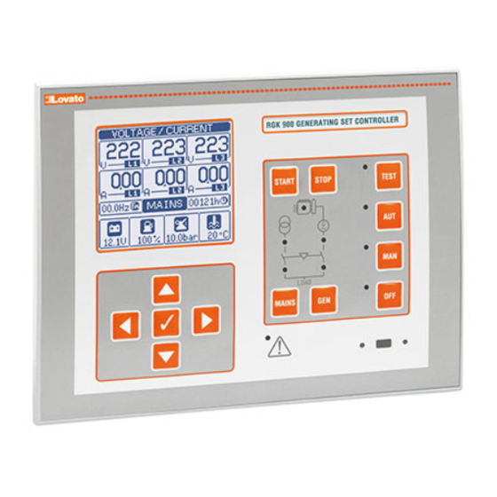
Manual revision history Introduzione Introduction Leunità di controllo RGK900 sono state progettate incorporando lo stato The RGK900 control units have been designed to offer state-of-the-art dell’arte delle funzioni richieste per le applicazioni su gruppi elettrogeni con functions for genset applications involving paralleling and load sharing. -
Page 3: Funzione Dei Tasti Frontali
LED motore in moto (verde) – Indica che il motore è in moto. L’RGK900 Engine running LED (green) – Indicates the engine is running. The rileva lo stato di motore in moto da diversi segnali (tensione/frequenza RGK900 detects the state of the engine running on the basis of several generatore, D+, AC, W, Pick-up ecc.). -
Page 4: Modi Operativi
L’avviamento viene eseguito secondo le modalità del modo automatico. starts in the programmed automatic mode. There is normally no load Normalmente non vengono effettuate commutazioni del carico. Per switching. If there is a mains outage while the RGK900 is in TEST mode, Doc: MHIT101C1110.docx 27/01/2014... -
Page 5: Messa In Tensione
RGK900, in caso di mancanza della rete mentre il sistema è in modo the load is switched to the generator. If mains voltage is restored, the TEST, il carico commuta sul generatore. Se la rete rientra, il carico rimane load with remain switched to the generator until the operating mode is sul generatore fintanto che non viene cambiata la modalità... -
Page 6: Menu Principale
Menu principale Main menu • Il menu principale è costituito da un insieme di icone grafiche che • The main menu is made up of a group of graphic icons (shortcuts) that permettono l’accesso rapido alle misure ed alle impostazioni. allow rapid access to measurements and settings. -
Page 7: Navigazione Fra Le Pagine Del Display
• Con i tasti ▲e ▼si cambia il valore della cifra selezionata. • Keys ▲and ▼change the selected digit • Con i tasti ◄e ► ci si sposta fra le cifre. • Keys ◄ and ► move through the digits. •... - Page 8 ◄ si switches commuta between commuta fra between l’indicazione Total/Partial Rete e Mains and Totali / indications Generatore Generator Parziali (RGK900) (RGK900) Summary of electrical Riassunto misure measurements elettriche Mains/Gen. Phase Ind, Rete / Indicazione Ind. indication Generatore fasi Measurements...
- Page 9 Corrente guasto a terra Earth fault current Percentuale Percentage Valore Present rispetto a assoluto absolute valore intervention attuale value intervento value Protezione termica Generator thermal generatore protection Percentage Percentuale intervention rispetto a value valore intervento Ore motore e Engine hour and work Contatori lavoro counters Ore lavoro...
- Page 10 Configurazioni Alternative alternative configurations Dati Present configurazio config. data ne attuale Numero Selected configuraz. config. selezionata number Stato I/O I/O status Digital I/O Stato I/O state digitali. In reverse = In reverse = enabled attivato Orologio datario Real time calendar clock Info page Pagina informativa...
-
Page 11: Pagina Analisi Armonica
Harmonic analysis page • Nell’ RGK900 è possibile abilitare il calcolo e la visualizzazione • In the RGK900 it is possible to enable the calculation of the FFT dell’analisi armonica FFT fino al 31.mo ordine delle seguenti misure: harmonic analysis up to the 31st order of the following measurements:... -
Page 12: Pagine Utente
Pagine utente nel capitolo impostazione parametri. Modelli e applicazioni Models and applications • RGK900 è predisposto per le seguenti applicazioni: • RGK900 is designed for the following applications: Singolo generatore in emergenza rete con parallelo Single generetor in AMF with temporary parallel with momentaneo (AMF con closed transition). - Page 13 Multiple generators in parallel on power bus, in AMF emergency with mains. Apparecchi utilizzabili: Devices: • • n x RGK900 + 1 x RGK900MC n x RGK900 + 1 x RGK900MC oppure • • n x RGK900SA + 1 x RGK900MC...
-
Page 14: Controlli Pid
Controlli PID PID control loops • La regolazione delle grandezze che permettono la sincronizzazione e la • The adjustment of the quantities that enable the synchronization and load ripartizione di carico avviene per mezzo di alcuni loop di controllo PID, sharing occurs by means of some PID control loops, which operate on che intervengono sulla velocità... - Page 15 • Con questa pagina visualizzata, premendo contemporanemente i • With this page displayed, pressing ◄and ► buttons simultaneously you tasti◄e ► si abilita il controllo manuale del segnale di velocità. take manual control of the speed signal. Pressing ▲or ▼manually Premendo ▲o ▼si incrementa o decrementa il numero di giri, quindi si increases/decreases the engine speed.
- Page 16 Taratura PID sfasamento Phase shift PID adjustment • Per il raggiungimento del controllo dello sfasamento è necessario • For the achievement of control of the phase shift is necessary to set the impostare il PID di fase che in questo caso è composto dal solo phase PID which in this case is composed by only the proportional coefficiente proporzionale P, impostato in P33.13.
- Page 17 parametri. Le modifiche apportate vengono memorizzate direttamente changes are stored directly in the setup memory. To exit setup, press nella memoria di setup. Per uscire dalla impostazione premere di nuovo again ◄ and ►. • The bar graph helps to visually highlight the error from setpoint and the ◄...
-
Page 18: Espandibilità
Espandibilità Expandability • Grazie al suo bus di espansione, l’ RGK900 può essere espanso con dei • Thanks to expansion bus, the RGK900 can be expanded with moduli aggiuntivi della serie EXP…. EXP… series modules. • E’ possibile installare un massimo di 4 moduli EXP…... -
Page 19: Risorse Aggiuntive
• The two channels can communicate at the same time. punto di vista hardware (tipo di interfaccia fisica) che dal punto di vista • Activating the Gateway function it is possible to use a RGK900 with both del protocollo di comunicazione. -
Page 20: Soglie Limite (Limx)
• The following table groups all the I/O and the internal variables managed un certo valore. • Di seguito una tabella che raccoglie tutte le variabili interne gestite dall’ by the RGK900. RGK900, con evidenziato il loro range (numero di variabili per tipo). CODE DESCRIPTION RANGE COD. -
Page 21: Variabili Da Remoto (Remx)
• You can enter all the variables managed by the RGK900 in the program applicazioni accessorie del gruppo elettrogeno. • Nella logica del programma è possibile inserire tutte le variabili gestite logic, such as inputs (INPx), limit thresholds (LIMx), remote variables internamente dall’RGK900, quali ingressi (INPx), soglie limite (LIMx),... -
Page 22: Test Automatico
(PLCx) che possono essere poi usate outputs of the RGK900, or as backup memories to build a more complex per comandare delle uscite dell’RGK900, oppure come memorie di logic, or also to control user-defined alarms (UAx). - Page 23 In the case of a fault, this is indicated on the viene indicata sul display dell’ RGK900 sia con la sigla che con la display of the RGK900 with both a code and with a description in the descrizione in lingua, nella pagina Diagnostica CAN.
-
Page 24: Modem Gsm-Gprs
• Sending data and event files on remote FTP server • Invio dati ed eventi su file remoto tramite server FTP It is possible to send all the events recorded by the RGK900 on a file E’ possibile inviare tutti gli eventi registrati dall’RGK900 su un file managed from an FTP server. -
Page 25: Configurazioni Multiple
IR programming port • La configurazione dei parametri dell’RGK900 si può effettuare tramite la • The parameters of the RGK900 can be configured through the front porta ottica frontale, attraverso la chiavetta di programmazione IR-USB optical port, using the IR-USB CX01 programming dongle or with the IR- CX01 oppure la chiavetta IR-WiFi CX02. -
Page 26: Impostazione Parametri Da Pc
RGK900 al disco del PC e viceversa. drive of the PC and vice versa. • Il trasferimento dei parametri da PC a RGK900 può essere parziale, cioè • The parameter may be partially transferred from the PC to the RGK900, solo i parametri dei menù... -
Page 27: Impostazione Parametri (Setup) Da Pannello Frontale
Impostazione dei parametri (setup) dal pannello frontale Setting of patameters (setup) from front panel • Per accedere al menu di programmazione dei parametri (setup): • To open the parameters programming menu (setup): predisporre la scheda in modalità OFF o turn the unit in OFF mode dalla normale visualizzazione misure, premere per richiamare il o in normal measurements view, press... - Page 28 RGK900. This • Rammentiamo che, per i soli dati di set-up modificabili da tastiera, è...
-
Page 29: Tabella Parametri
Tabella parametri Parameter table M01 – UTILITA’ Default Range M01 - UTILITY Default Range P01.01 Lingua English English P01.01 Language English English Italiano Italiano Francais Francais Espanol Espanol Portuguese Portuguese P01.02 Impostazione orologio alla alimentazione OFF-ON P01.02 Set real time clock at power on OFF-ON P01.03 Modalità... - Page 30 M04 – CONFIGURAZIONI Default Range M04 - CONFIGURATIONS Default Range (CNFn, n=1…4) (CNFn, n=1…4) P04.n.01 Tensione nominale 50-50000 P04.n.01 Rated voltage 50-50000 P04.n.02 Tipo di collegamento L1-L2-L3-N L1-L2-L3-N P04.n.02 Type of connection L1-L2-L3-N L1-L2-L3-N L1-L2-L3 L1-L2-L3 P04.n.03 Tipo controllo tensioni P04.n.03 Type of voltage control L-L + L-N L-L + L-N...
- Page 31 con ingresso a alta sensibilità (per segnali deboli). CAN = RPM letti dalla ECU P07.02 - Ratio between the RPM and the frequency of the W or pick-up signal. Can be set motore tramite CAN bus. manually or acquired automatically through the following procedure: P07.02 - Rapporto fra RPM e frequenza del segnale W o pick-up.
- Page 32 P09.09 - Se la temperatura del motore è superiore a questa soglia (motore già caldo) , la P09.10 - P09.11 – Defines the thresholds for on-off control of the output programmed with the presa del carico viene fatta dopo 5s invece che dopo il tempo normale di presenza preheating function impostato con P14.05.
- Page 33 P11.24 Soglia stacco aria 1-100 P11.24 Air disconnect threshold 1-100 Nr. Tentativi avviamento con aria 1-10 No. of attempted starts with air 1-10 P11.25 P11.25 P11.26 Modo tentativi aria Consecutivi Consecutivi P11.26 Air attempts mode Consecutive Consecutive Alternati Alternating P11.27 Modo tentativi di avviamento aria P11.27 Compressed air starting attempts mode...
- Page 34 P13.12 – Ritardo di intervento di minima frequenza. P13.11 – Min. frequency intervention threshold (can be disabled). P13.13 – OFF = Controllo bus / rete disabilitato. INT = Controllo bus / rete affidato all’RGK900. P13.12 – Min. frequency intervention delay.
- Page 35 P14.12 – Min. frequency intervention delay. all’RGK900. EXT = Controllo generatore affidato ad un apparecchio esterno. E’ P14.13 – OFF = Generator control disabled. INT = Generator controlled by RGK900. EXT = possibile utilizzare un ingresso programmabile con la funzione Controllo generatore Generator controlled by external device.
- Page 36 Note: This menu is divided into 32 sections that refer to 32 possible digital inputs Nota: Questo menu è diviso in 32 sezioni, riferite ai 32 possibili ingressi digitali INP1…INP32, which can be managed by the RGK900; INP1..INP12 on the base INP1…INP32 gestibili dall’RGK900, di cui INP1..INP12 sulla scheda base e board and INP13…INP32 on any installed expansion modules.
- Page 37 CAN che aderiscono alla norma SAE J1939. messages on the CAN that meet SAE J1939 standards. P21.02- Modo di comunicazione sul CAN bus. M = solo Misure. L’ RGK900 cattura solo le P21.02- Communication mode on CAN bus. M = Measurements only. The RGK900 only misure (pressioni, temperature ecc) inviate sul CAN dalla ECU del motore.
- Page 38 cumulativi Lampada gialla (preallarme) o Lampada rossa (allarme critico), gestibili ON = CAN diagnostics messages with a direct correspondence in the alarms table con le loro proprietà. ON = I messaggi diagnostici da CAN che hanno un diretto also generate this alarm, as well as activating the yellow and red lamp. See the corrispondente nella tabella allarmi generano anche questo allarme,oltre ai consueti alarms chapter for the list of redirectable alarms.
- Page 39 For example, if this parameter is programmed for O+M, the mancata chiusura e la conseguente generazione dell’allarme A41 Anomalia Operating mode output will be enabled when the RGK900 is in OFF or MAN mode. contattore rete, il motore viene avviato e il carico commutato sul generatore.
- Page 40 P25.n.01 - Signal that increments the count (on the output side). This may be the start-up of messa in tensione dellì RGK900 (ON), il superamento di una soglia (LIMx), the RGK900 (ON), when a threshold is exceeded (LIMx), an external input is l’attivazione di un ingresso esterno (INPx), una condizione logica (PLCx) ecc.
- Page 41 impostato senza entrare in setup, tramite la funzione rapida nel menu comandi che the quick function in the commands menu which lets you view the measurements consente di vedere le misure mentre si esegue la taratura. while calibrating. P28.03 - Descrizione della misura associata al sensore resistivo programmabile (testo libero). P28.03 - Description of the measurement associated with the programmable resistive sensor P28.04 - Unità...
- Page 42 M = energia attiva rete. kWh G = managed by the RGK900. kWh M = Mains active energy. kWh G = Generator active energia attiva generatore. Kvarh M = Energia reattiva rete. Kvarh G = Energia energy.
- Page 43 P32.13 – Tempo di ritardo riferito alla soglia del parametro precedente. P32.13 - Delay time referred to the threshold of the previous parameter. P32.14 – Soglia di potenza reattiva negativa (capacitiva) oltre la quale viene generato l’allarme P32.14 - Negative reactive power threshold (capacitive) beyond which the alarm A63 A63 Massima potenza reattiva.
- Page 44 P34.07 Soglia allarme banda 0 - 100 P34.07 Band alarm threshold 0 - 100 Ritardo allarme banda 0 - 100 Band alarm delay 0 - 100 P34.08 P34.08 P34.09 AVR dt 0.04 0.01 – 10.00 P34.09 AVR dt 0.04 0.01 – 10.00 P34.10 AVR kp Volt 0 - 1000...
- Page 45 Nota : Questi parametri vengono allineati automaticamente fra tutti gli RGK900 collegati Note : These parameters are automatically aligned among all RGK900 that are connected sulla line CAN bus di load sharing. together on the load sharing CAN bus line.
- Page 46 Entrambi Entrambi ROCOF df/dt Hz / OFF/ 0.1 – 10.0 ROCOF df/dt Hz / OFF/ 0.1 – 10.0 P36.19 P36.19 P36.20 ROCOF campioni 3-30 P36.20 ROCOF samples 3-30 P36.21 Abilitazione vector shift P36.21 Vector shift enable RETE MAINS RETE+GEN MAINS+GEN P36.22 Apertura per vector shift RETE...
-
Page 47: Allarmi
• In seguito al verificarsi di uno o più allarmi, l’RGK900 ha un • In the case of one or more alarms, the behaviour of the RGK900 depends comportamento dipendente dalla impostazione delle proprietà degli on the properties settings of the active alarms. -
Page 48: Proprietà Degli Allarmi
Proprietà degli allarmi Alarm properties Ad ogni allarme, compresi gli allarmi utente (User Alarms, UAx) possono Various properties can be assigned to each alarm, including user alarms (User essere assegnate diverse proprietà: Alarms, UAx): • • Allarme abilitato - Abilitazione generale dell’allarme. Se non abilitato è Alarm enabled - General enabling of the alarm. -
Page 49: Tabella Allarmi
Tabella allarmi Alarm table DESCRIZIONE PROPRIETA’ ALLARMI DI DEFAULT DESCRIPTION DEFAULT ALARM PROPERTIES Preallarme temperatura motore Engine temperature warning ● ● ● ● ● ● ● ● (sensore analogico) (analog sensor) Alta temperatura motore High engine temperature (analog ● ● ● ●... - Page 50 Guasto a terra generatore Generator earth fault ● ● ● ● ● ● ● ● ● ● ● ● ● ● Errata sequenza fasi generatore Generator phase sequence error ● ● ● ● ● ● ● ● ● ● ● ● Errata sequenza fasi rete Mains phase sequence error ●...
- Page 51 UA11 UA11 UA11 UA11 UA12 UA12 UA12 UA12 UA13 UA13 UA13 UA13 UA14 UA14 UA14 UA14 UA15 UA15 UA15 UA15 UA16 UA16 UA16 UA16 Doc: MHIT101C1110.docx 27/01/2014 p. 51 / 83...
-
Page 52: Descrizione Degli Allarmi
Descrizione degli allarmi Alarm description DESCRIZIONE MOTIVAZIONE ALLARME DESCRIPTION ALARM EXPLANATION Preallarme temperatura motore Engine temperature Temperatura motore superiore alla soglia di Engine temperature higher than prealarm (sensore analogico) prealarm (analog sensor) preallarme impostata con P09.06. threshold set in P09.06. Alta temperatura motore Temperatura motore superiore alla soglia di High engine temperature... - Page 53 Richiesta manutenzione 3 the operating hours and the alarm. l’allarme. Maintenance request 3 Errore di sistema Si è verificato un errore interno all’RGK900. System error Vedere capitolo Errori di sistema per possibili RGK900 internal error. SeeSystem errors rimedi. chapter for possible solutions.
- Page 54 Allarme da carica batteria Allarme generato dall’ingresso programmato con Battery charger alarm Alarm generated by the input programmed la funzione Allarme carica batteria connesso ad with the function Battery charger alarm un caricabatteria esterno quando la tensione di connected to an external battery charger rete è...
-
Page 55: Tabella Funzioni Ingressi
Tabella funzioni ingressi Input function table • • La tabella seguente riporta tutte le funzioni che possono essere The following table shows all the functions that can be attributed to the associate agli ingressi digitali programmabili INPn. INPn programmable digital inputs. •... - Page 56 utilizza il teleruttore generatore ma viene utilizzato un generator contactor isn't used and a thermal magnetic interruttore comandato manualmente. Questa funzione è circuit breaker is used. This function is required to start necessaria per avviare il generatore essendo certi che il the generator when certain the load is disconnected.
-
Page 57: Tabella Funzioni Uscite
Vedere parametro P11.27. P11.27. Operating mode Output energized when the RGK900 is in one of the Modo funzionamento Uscita eccitata quando l’RGK900 si trova in una delle modes set with parameter P23.13. modalità impostate con il parametro P23.13. - Page 58 Allarmi UA1..UAx Uscita eccitata quando l’allarme UAx è attivo (x=1…16). (x=1…16). Increase speed Output activated when the unit requires the increase of the Aumenta giri Uscita attivata quando l’unità richiede l’aumento dei giri del engine speed and the error with respect to the desired motore e l’errore rispetto alla velocità...
-
Page 59: Menu Comandi
Utente Azzera il contatore parziale della Reset mains partial energy. User Resets the mains partial energy rete energia rete. (solo per RGK900) counter. (only for RGK900) Reset contatore parziale energia Utente Azzera il contatore parziale della Reset generator partial User Resets the generator partial energy generatore. -
Page 60: Installazione
Installazione Installation • RGK900 è destinato al montaggio da incasso. Con il corretto montaggio • RGK900 is designed for flush-mount installation. With proper gasket della guarnizione garantisce una protezione frontale IP65. mounting, it guarantees IP65 front protection. • Inserire il sistema nel foro del pannello, accertandosi che la guarnizione •... -
Page 61: Schemi Di Connessione
The CANbus connection has two 120-Ohm termination resistors at both 120 Ohm agli estremi del bus. Per collegare la resistenza incorporata ends of the bus. To connect the resistor incorporated in the RGK900 nella scheda RGK900 effettuare un ponte fra TR e CAN-L. - Page 62 DC coil relay DC coil relay MAX 50mA MAX 50mA F0,1A F0,1A RGK900 - Applicazione tipica di singolo gruppo in parallelo rete RGK900 – Typical application with single genset in parallel to mains LOAD GENERATOR MAINS 36 37 Doc: MHIT101C1110.docx 27/01/2014...
- Page 63 RGK900SA - Applicazione tipica di paralleo fra gruppi in isola RGK900SA - Typical application with multiple genset paralleling in island LOAD GENERATOR CONT. GENERATOR 1 36 37 GENERATOR CONT. GENERATOR N..36 37 Doc: MHIT101C1110.docx 27/01/2014 p. 63 / 83...
- Page 64 RGK900MC - Applicazione tipica di parallelo di generatori multipli con rete RGK900MC - Typical application with multiple generators in parallel with mains LOAD GENERATORS MAINS CONTACTOR CONTACTOR GENERATORS MAINS 36 37 53 54 55 57 58 Doc: MHIT101C1110.docx 27/01/2014 p. 64 / 83...
- Page 65 The CANbus connection has two 120-Ohm termination resistors at both 120 Ohm agli estremi del bus. Per collegare la resistenza incorporata ends of the bus. To connect the resistor incorporated in the RGK900 nella scheda RGK900 effettuare un ponte fra TR e CAN-L. Per la board, jumper TR and CAN-L.
- Page 66 RGK900SA + RGK900MC – Collegamento CANbus per load sharing / gestione carico RGK900SA + RGK900MC – Wiring of CANbus for load sharing and management SUPPLY SUPPLY E.C.U. Governor E.C.U. Governor L H SG L H SG 120R 120R GOV-1 AVR-1 AVR-2 GOV-1 AVR-1...
-
Page 67: Tabella Connessioni Governor
Tabella connessioni governor Governor wiring table AMBAC EC5000 / EC5100 / EC5110 RGK900 PAR. DESCRIPTION VALUE P33.1 Control type Analog. GOV-1 P33.2 Polarity P33.3 Ref. level 5Vdc P33.4 V max 6,5Vdc P33.5 V min 3,5Vdc CW673C RGK900 DESCRIPTION VALUE P33.1 Control type Analog. - Page 68 DPG 2201 RGK900 PAR. DESCRIPTION VALUE P33.1 Control type Analog. GOV-1 P33.2 Polarity P33.3 Ref. level 0Vdc P33.4 V max 0,5Vdc P33.5 V min -0,5Vdc DPG 2401 PAR. DESCRIPTION VALUE RGK900 P33.1 Control type Analog. GOV-1 P33.2 Polarity P33.3 Ref. level 0Vdc P33.4...
- Page 69 DETROIT DIESEL DDEC III PAR. DESCRIPTION VALUE RGK900 P33.1 Control type Analog. GOV-1 P33.2 Polarity P33.3 Ref. level 2,5Vdc P33.4 V max 5Vdc P33.5 V min 0Vdc DDEC IV PAR. DESCRIPTION VALUE RGK900 P33.1 Control type Analog. GOV-1 P33.2 Polarity P33.3...
- Page 70 HEINZMANN KG SERIES (6-04 TO 10-04) PAR. DESCRIPTION VALUE RGK900 P33.1 Control type Analog. GOV-1 P33.2 Polarity P33.3 Ref. level 2,5Vdc P33.4 V max 5Vdc P33.5 V min 0Vdc Pandaros RGK900 PAR. DESCRIPTION VALUE P33.1 Control type Analog. GOV-1 P33.2 Polarity P33.3...
- Page 71 ADEC 2000 / 4000 PAR. DESCRIPTION VALUE RGK900 P33.1 Control type Analog. GOV-1 P33.2 Polarity P33.3 Ref. level 4,5Vdc P33.4 V max 8Vdc P33.5 V min 1Vdc See MTU manual befor installation MDEC 2000 / 4000 RGK900 PAR. DESCRIPTION VALUE P33.1...
- Page 72 VOLVO 873979 ( G.A.C. 5100 - 5500 SERIES) PAR. DESCRIPTION VALUE RGK900 P33.1 Control type Analog. GOV-1 P33.2 Polarity P33.3 Ref. level 4,5Vdc P33.4 V max 6Vdc P33.5 V min 3Vdc EDC III PAR. DESCRIPTION VALUE RGK900 P33.1 Control type Analog.
- Page 73 PAR. DESCRIPTION VALUE RGK900 P33.1 Control type Analog. GOV-1 P33.2 Polarity P33.3 Ref. level 0Vdc P33.4 V max 2,5Vdc P33.5 V min -2,5Vdc Doc: MHIT101C1110.docx 27/01/2014 p. 73 / 83...
-
Page 74: Tabella Connessioni Avr
Tabella connessioni AVR AVR wiring table BASLER AVC 63-12 RGK900 PAR. DESCRIPTION VALUE P34.1 Control type Analog. AVR 1 P34.2 Polarity P34.3 Ref. level 0Vdc AVR 2 P34.4 V max 1Vdc P34.5 V min -1Vdc DECS 15, DECS 100 RGK900 PAR. - Page 75 PAR. DESCRIPTION VALUE RGK900 P34.1 Control type Analog. AVR 1 P34.2 Polarity P34.3 Ref. level 0Vdc AVR 2 P34.4 V max 1Vdc P34.5 V min -1Vdc COSIMAT COSIMAT-N PAR. DESCRIPTION VALUE RGK900 P34.1 Control type Analog. AVR 1 P34.2 Polarity P34.3...
- Page 76 LEROY SOMER R230 / R438 / R448 / R449 PAR. DESCRIPTION VALUE RGK900 P34.1 Control type Analog. AVR 1 P34.2 Polarity P34.3 Ref. level 0Vdc AVR 2 P34.4 V max 1Vdc P34.5 V min -1Vdc R610 3F PAR. DESCRIPTION VALUE RGK900 P34.1...
- Page 77 M40FA640A PAR. DESCRIPTION VALUE RGK900 P34.1 Control type Analog. AVR 1 P34.2 Polarity P34.3 Ref. level 0Vdc AVR 2 P34.4 V max 0,3Vdc P34.5 V min -0,3Vdc M40FA644A PAR. DESCRIPTION VALUE RGK900 P34.1 Control type Analog. AVR 1 P34.2 Polarity P34.3...
- Page 78 DER 1 Alternative connection PAR. DESCRIPTION VALUE RGK900 P34.1 Control type Analog. AVR 1 P34.2 Polarity P34.3 Ref. level 0Vdc AVR 2 P34.4 V max +10Vdc P34.5 V min -10Vdc NOTE: JP1 ( 27-28) and JP2 (31-31) open NEWAGE INTERNATIONAL MA325, MA327 PAR.
-
Page 79: Disposizione Morsetti
Disposizione morsetti Terminals arrangement RGK900 – RGK900SA 23 24 25 26 MAINS / BUS CURRENT CAN 1 RS485 AVR-1 SLOT 1 AVR-2 GOV-1 SLOT 2 CAN 2 SLOT 3 INP 9 INP 10 INP 11 SLOT 4 INP 12 BATTERY... -
Page 80: Dimensioni Meccaniche (Mm)
Dimensioni meccaniche (mm) Mechanical dimensions (mm) Foratura pannello (mm) Panel cutout (mm) Doc: MHIT101C1110.docx 27/01/2014 p. 80 / 83... - Page 81 Caratteristiche tecniche Technical characteristics Alimentazione Supply Tensione nominale di batteria 12 o 24VDC indifferentemente Battery rated voltage 12 or 24VDC indifferently Corrente massima assorbita 400mA a 12VDC e 200mA a 24VDC Maximum current consumption 400mA at 12VDC e 200mA at 24VDC Potenza massima assorbita/dissipata 4,8W Maximum power consumption/dissipation...
- Page 82 Uscite statiche OUT3 - OUT 6 (Uscite in tensione + batteria) SSR output OUT3 - OUT 6 (+ battery voltage output) Tipo di uscita 4 x 1 NO + terminale comune Output type 4 x 1 NO + one common terminal Tensione d’impiego 12-24V= da batteria Rated voltage...
- Page 83 Contenitore Housing Esecuzione Da incasso Version Flush mount Materiale Policarbonato Material Polycarbonate Grado di protezione frontale IP65 sul fronte – IP20 sui morsetti Degree of protection IP65 on front - IP20 terminals Peso 960g Weight 960g Omologazioni e conformità Certifications and compliance Omologazioni cULus (in corso) Certifications...
Need help?
Do you have a question about the RGK900 and is the answer not in the manual?
Questions and answers