Table of Contents
Advertisement
Available languages
Available languages
Quick Links
LOV TO ELECTRIC S.P. .
24020 GORLE (BERGAMO) ITALIA
VIA DON E. MAZZA, 12
TEL. 035 4282111
L
E
E-mail info@
ovato
lectric.com
L
E
Web
www.
ovato
lectric.com
W RNING!
– Carefully read the manual before the installation or use.
– This equipment is to be installed by qualified personnel, complying to current standards, to avoid
damages or safety hazards.
– Before any maintenance operation on the device, remove all the voltages from measuring and supply inputs and short-
circuit the CT input terminals.
– The manufacturer cannot be held responsible for electrical safety in case of improper use of the equipment.
– Products illustrated herein are subject to alteration and changes without prior notice. Technical data and descriptions
in the documentation are accurate, to the best of our knowledge, but no liabilities for errors, omissions or
contingencies arising there from are accepted.
– A circuit breaker must be included in the electrical installation of the building. It must be installed close by the
equipment and within easy reach of the operator. It must be marked as the disconnecting device of the equipment:
IEC /EN 61010-1 § 6.11.3.1.
– Clean the device with a soft dry cloth; do not use abrasives, liquid detergents or solvents.
TTENTION !
– Lire attentivement le manuel avant toute utilisation et installation.
– Ces appareils doivent être installés par un personnel qualifié, conformément aux normes en vigueur en
matière d'installations, afin d'éviter de causer des dommages à des personnes ou choses.
– Avant toute intervention sur l'instrument, mettre les entrées de mesure et d'alimentation hors tension et court-circuiter
les transformateurs de courant.
– Le constructeur n'assume aucune responsabilité quant à la sécurité électrique en cas d'utilisation impropre du
dispositif.
– Les produits décrits dans ce document sont susceptibles d'évoluer ou de subir des modifications à n'importe quel
moment. Les descriptions et caractéristiques techniques du catalogue ne peuvent donc avoir aucune valeur
contractuelle.
– Un interrupteur ou disjoncteur doit être inclus dans l'installation électrique du bâtiment. Celui-ci doit se trouver tout
près de l'appareil et l'opérateur doit pouvoir y accéder facilement. Il doit être marqué comme le dispositif
d'interruption de l'appareil : IEC/ EN 61010-1 § 6.11.3.1.
– Nettoyer l'appareil avec un chiffon doux, ne pas utiliser de produits abrasifs, détergents liquides ou solvants.
CHTUNG!
– Dieses Handbuch vor Gebrauch und Installation aufmerksam lesen.
– Zur Vermeidung von Personen- und Sachschäden dürfen diese Geräte nur von qualifiziertem
Fachpersonal und unter Befolgung der einschlägigen Vorschriften installiert werden.
– Vor jedem Eingriff am Instrument die Spannungszufuhr zu den Messeingängen trennen und die Stromwandler
kurzschlie en.
– Bei zweckwidrigem Gebrauch der Vorrichtung übernimmt der Hersteller keine Haftung für die elektrische Sicherheit.
– Die in dieser Broschüre beschriebenen Produkte können jederzeit weiterentwickelt und geändert werden. Die im
Katalog enthaltenen Beschreibungen und Daten sind daher unverbindlich und ohne Gewähr.
– In die elektrische Anlage des Gebäudes ist ein Ausschalter oder Trennschalter einzubauen. Dieser muss sich in
unmittelbarer Nähe des Geräts befinden und vom Bediener leicht zugänglich sein. Er muss als Trennvorrichtung für das
Gerät gekennzeichnet sein: IEC/ EN 61010-1 § 6.11.3.1.
– Das Gerät mit einem weichen Tuch reinigen, keine Scheuermittel, Flüssigreiniger oder Lösungsmittel verwenden.
DVERTENCI
– Leer atentamente el manual antes de instalar y utilizar el regulador.
– Este dispositivo debe ser instalado por personal cualificado conforme a la normativa de instalación
vigente a fin de evitar daños personales o materiales.
– Antes de realizar cualquier operación en el dispositivo, desconectar la corriente de las entradas de alimentación y
medida, y cortocircuitar los transformadores de corriente.
– El fabricante no se responsabilizará de la seguridad eléctrica en caso de que el dispositivo no se utilice de forma
adecuada.
– Los productos descritos en este documento se pueden actualizar o modificar en cualquier momento. Por consiguiente,
las descripciones y los datos técnicos aquí contenidos no tienen valor contractual.
– La instalación eléctrica del edificio debe disponer de un interruptor o disyuntor. Éste debe encontrarse cerca del
dispositivo, en un lugar al que el usuario pueda acceder con facilidad. Además, debe llevar el mismo marcado que el
interruptor del dispositivo (IEC/ EN 61010-1 § 6.11.3.1).
– Limpiar el dispositivo con un trapo suave; no utilizar productos abrasivos, detergentes líquidos ni disolventes.
UPOZORNĚNÍ
AVERTIZARE!
GB
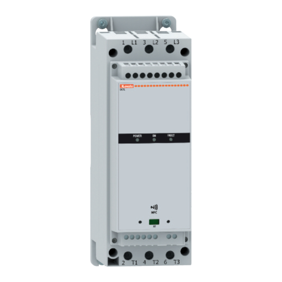
THYRISTOR MODULES
Instruction manual
DCTL...
TTENZIONE!
– Leggere attentamente il manuale prima dell'utilizzo e l'installazione.
– Questi apparecchi devono essere installati da personale qualificato, nel rispetto delle vigenti normative
impiantistiche, allo scopo di evitare danni a persone o cose.
– Prima di qualsiasi intervento sullo strumento, togliere tensione dagli ingressi di misura e di alimentazione e
cortocircuitare i trasformatori di corrente.
– Il costruttore non si assume responsabilità in merito alla sicurezza elettrica in caso di utilizzo improprio del dispositivo.
– I prodotti descritti in questo documento sono suscettibili in qualsiasi momento di evoluzioni o di modifiche. Le
descrizioni ed i dati a catalogo non possono pertanto avere alcun valore contrattuale.
– Un interruttore o disgiuntore va compreso nell'impianto elettrico dell'edificio. Esso deve trovarsi in stretta vicinanza
dell'apparecchio ed essere facilmente raggiungibile da parte dell'operatore. Deve essere marchiato come il dispositivo
di interruzione dell'apparecchio: IEC/ EN 61010-1 § 6.11.3.1.
– Pulire l'apparecchio con panno morbido, non usare prodotti abrasivi, detergenti liquidi o solventi.
UW G !
ПРЕДУПРЕЖДЕНИЕ!
DİKKAT!
G
B
1
Advertisement
Chapters
Table of Contents

Subscribe to Our Youtube Channel
Related Manuals for LOVATO ELECTRIC DCTL Series


Summary of Contents for LOVATO ELECTRIC DCTL Series
- Page 1 THYRISTOR MODULES Instruction manual LOV TO ELECTRIC S.P. . 24020 GORLE (BERGAMO) ITALIA VIA DON E. MAZZA, 12 TEL. 035 4282111 E-mail info@ ovato lectric.com www. ovato lectric.com DCTL... W RNING! TTENZIONE! – Carefully read the manual before the installation or use. –...
-
Page 2: Table Of Contents
INTRODUCTION The DCTL series of thyristor modules is intended to be used in power factor correction panels where a fast compensation is required due to a very fast variation of the inductive load. They are normally controlled by a fast power factor controller like LOVATO DCRG8-DCRG 8F series controllers, even though they are compatible with any type of fast compensation controller. -
Page 3: Front Status Leds
PARAMETER SETTING FROM PC – With the LOVATO Electric Xpress remote control and configuration software is possible to read and modify the parameters of DCTL and save them on a file on the hard disk of the PC, or alternatively you can upload a parameters file from the PC and download it into the DCTL thyristor module. -
Page 4: Parameter Table
PARAMETERS TABLE – The available sub-menus are shown in the following table: Code MENU DESCRIPTION GENERAL Capacitor bank characteristics PROTECTIONS Protections thresholds configuration PASSWORD Password management M01 – GENERAL Cod. Description Default Range P01.01 Capacitor bank rated power kvar (DCTL power size) 50...120% of DCTL power 7.5 kvar 9.0 kvar... -
Page 5: Alarms
ALARMS – When an alarm occurs, the red FAULT LED on the front panel will blink for as long as an alarm is active. The number of flashes identifies the type of active alarm (e.g. 1 flash = A01 alarm, 2 flashes = A02 alarm, 3 flahses = A03 alarm, etc...). -
Page 6: Recommendations
RECOMMENDATIONS – Switch off power to the thyristor module every time you need to work on the electrical or mechanical equipment of the system or machine. – A disconnecting device, such as switch disconnector, line contactor, etc. must always be included to cut off the power supply. –... - Page 7 Command with dry contact Moduli a tiristori DCTL Tyristor module DCTL Induttori raccomandati Recommended inductors Command via RS485 serial communication from DCRG 8F controller REQUIREMENTS – The DCRG 8F controller must be equipped with the optional RS485 communication module code EXP10 12 –...
-
Page 8: Wiring Dimensions
MECHANICAL DIMENSIONS[MM] SIZE 1: SIZE 2: DCTLA 400 0075 - DCTLA 400 0150 - DCTLA 400 0300 DCTLA 400 0500 - DCTLA 480 0600 - DCTLA 690 0300 - DCTLA 690 0500 DCTLA 480 0090 - DCTLA 480 0180 - DCTLA 480 0360 171.5 Ø5.40 Ø5.40... -
Page 9: Terminal Layout
TERMINAL LAYOUT A1 A2 11 14 12 CONTROL C IN1 NTC NTC POWER RATINGS Code DCTL DCTL DCTL DCTL DCTL DCTL DCTL DCTL DCTL DCTL DCTL DCTL DCTL 0075 0150 0300 0500 1000 0090 0180 0360 0600 1200 0300 0500 1000 Rated operating voltage Us 400VAC 50/60Hz... -
Page 10: Technical Characteristics
TECHNICAL CHARACTERISTICS uxiliary supply: terminals 1- 2 Connections - relay Us rated voltage 100 - 240VAC Terminal types Screw-type (fixed) Operating range 90 - 264VAC Wire cross-section (min and max) 0.2...4mm (26...10 AWG) Frequency 45 - 66 Hz Tightening torque 0.8Nm (7 lb.in) Drawn/dissipated power Size 1... - Page 11 MODUŁY TYRYSTOROWE Instrukcja obsługi LOV TO ELECTRIC S.P. . 24020 GORLE (BERGAMO) ITALIA VIA DON E. MAZZA, 12 TEL. 035 4282111 E-mail info@ ovato lectric.com www. ovato lectric.com DCTL... W RNING! TTENZIONE! – Carefully read the manual before the installation or use. –...
-
Page 12: Wprowadzenie
NFc przy użyciu tych samych urządzeń sprzętowych i oprogramowania, które są stosowane w innych urządzeniach LOVAtO electric (złącza cX 01/cX 02, oprogramowanie Xpress, aplikacja LOVAtO SAM1 lub aplikacja LOVAtO NFc). -
Page 13: Wskaźniki Led Na Panelu Przednim
UStAWiANie pArAMetróW prZeZ KOMpUter – poprzez oprogramowanie do konfiguracji i sterowania zdalnego Lovato electric Xpress można odczytywać i zmieniać parametry DctL oraz zapisać je w pliku na dysku komputera lub pobrać parametry zapisane na pliku na komputerze do DctL. – połączenie pomiędzy DctL i komputerem można wykonać poprzez przedni port optyczny (korzystając z modułów USB o kodzie cX 01 lub Wi-Fi o kodzie cX 02) bądź poprzez opcjonalną kartę rS485 (kod eXc 1042). -
Page 14: Tabela Parametrów
tABeLA pArAMetróW – Dostępne menu przedstawiono w poniższej tabeli: MeNU OpiS OGóLNe charakterystyka baterii kondensatorów ZABeZpiecZeNiA Konfiguracja wartości progowych zabezpieczenia HASŁO Zarządzanie hasłem M01 – OGóLNe Opis Domyślne Zakres P01.01 Moc znamionowa baterii kondensatorów kvar (rozmiar DctL) 50...120% zakresu DctL 7,5 kvar 9,0 kvar 15,0 kvar... -
Page 15: Alarmy
ALArMy – po włączeniu się alarmu czerwony wskaźnik LeD FAULt na przednim panelu miga tak długo, jak długo alarm jest aktywny. Liczba mignięć określa typ aktywnego alarmu (np. 1 mignięcie = alarm A01, 2 mignięcia = alarm A02 itd.). Znaczenie alarmu opisano w poniższych tabelach. –... -
Page 16: Zalecenia
ZALeceNiA – Należy odłączyć zasilanie modułów tyrystorowych za każdym razem, kiedy konieczne jest wykonanie czynności w zakresie układu elektrycznego i/lub mechanicznego bądź instalacji. – Należy zawsze przewidzieć urządzenie odłączające (wyłącznik sekcyjny, rozłącznik linii itd.) zasilania. – Nie należy instalować modułu tyrystorowego w otoczeniach zawierających materiały wybuchowe lub gazy łatwopalne. –... - Page 17 Sterowanie zestykiem bezpotencjałowym Moduły tyrystorowe DctL Moduli a tiristori DCTL Tyristor module DCTL Tyristor module DCTL Zalecane dławiki Induttori raccomandati Recommended inductors Recommended inductors Sterowanie przez komunikację szeregową rS485 z automatycznego regulatora DcrG 8F WyMAGANiA – regulator DcrG 8F musi być wyposażony w opcjonalny moduł komunikacyjny rS485 o kodzie eXp10 12. –...
-
Page 18: Wymiary Mechaniczne
WyMiAry MecHANicZNe rOZMiAr 1: rOZMiAr 2: DctLA 400 0075 - DctLA 400 0150 - DctLA 400 0300 DctLA 400 0500 - DctLA 480 0600 - DctLA 690 0300 - DctLA 690 0500 DctLA 480 0090 - DctLA 480 0180 - DctLA 480 0360 171.5 Ø5.40 Ø5.40... -
Page 19: Rozmieszczenie Zacisków
rOZMieSZcZeNie ZAciSKóW A1 A2 11 14 12 CONTROL C IN1 NTC NTC MOce ZNAMiONOWe DCTLA DCTLA DCTLA DCTLA DCTLA DCTLA DCTLA DCTLA DCTLA DCTLA DCTLA DCTLA DCTLA 0075 0150 0300 0500 1000 0090 0180 0360 0600 1200 0300 0500 1000 Znamionowe napięcie robocze Us 400 VAc 50/60 Hz 400...480 VAc 50/60 Hz... -
Page 20: Parametry Techniczne
pArAMetry tecHNicZNe Zasilanie pomocnicze: zaciski A1 – A2 Podłączenie zasilania – przekaźnik Napięcie znamionowe Us 100 - 240 VAc typ zacisków śrubowe (stałe) Zakres napięcia pracy 90 – 264 VAc przekrój przewodów (min. i maks.) 0.2...4mm (26...10 AWG) częstotliwość 45 – 66 Hz Moment dokręcenia 0,8Nm (7 lb.in) pobór/rozproszenie mocy...
Need help?
Do you have a question about the DCTL Series and is the answer not in the manual?
Questions and answers