Table of Contents
Advertisement
LOVATO ELECTRIC S.P.A.
24020 GORLE (BERGAMO) ITALIA
VIA DON E. MAZZA, 12
TEL. 035 4282111
TELEFAX (Nazionale): 035 4282200
TELEFAX (International): +39 035 4282400
L
E
E-mail info@
ovato
lectric.com
L
E
Web
www.
ovato
lectric.com
INDICE GENERALE ................................................................. Pag. 1
GENERALITÀ ..........................................................................
Descrizione del frontale ..........................................................
MODO DI FUNZIONAMENTO ..................................................
Funzionamento OFF ................................................................
Funzionamento MANUALE .....................................................
Funzionamento AUTOMATICO ...............................................
Funzionamento TEST .............................................................
DESCRIZIONE DEL FUNZIONAMENTO ..................................
Ciclo di avviamento gruppo elettrogeno ................................
Ciclo di arresto gruppo elettrogeno .......................................
Segnale motore avviato .........................................................
Presenza tensione rete ...........................................................
Presenza tensione generatore ................................................
Commutazione Rete/Gener. e Gener./Rete .............................
Intervento allarmi ..................................................................
Visualizzazione delle misure ..................................................
FUNZIONI ..............................................................................
Test automatico .....................................................................
Abilitazione e disabilitazione test aut. ....................................
Arresto di emergenza .............................................................
Avviamento a distanza ...........................................................
Telecommutazione .................................................................
Funzionamento per motopompa ............................................
Contaore funz. gruppo elettrogeno ........................................
Intervallo di manutenzione .....................................................
Allarme cumulativo ................................................................
Controllo remoto ...................................................................
INFORMAZIONI, ALLARMI E ERRORI ...................................
Informazioni ..........................................................................
Tabella messaggi ...................................................................
Allarmi ...................................................................................
Tabella allarmi .......................................................................
Errori .....................................................................................
Tabella errori .........................................................................
INGRESSI E USCITE ..............................................................
Tabella ingressi ......................................................................
Tabella uscite .........................................................................
PROGRAMMAZIONE .............................................................
PARAMETRI ..........................................................................
Tabella setup base .................................................................
Tabella setup esteso ..............................................................
Tabella setup allarmi utente ...................................................
CARATTERISTICHE TECNICHE ..............................................
NORMATIVE DI RIFERIMENTO ..............................................
SCHEMI DI COLLEGAMENTO ...............................................
CONNESSIONI MORSETTIERA RGAM ...................................
DIMENSIONI ..........................................................................
ATTENZIONE!!
Questo apparecchio deve essere installato da personale qualificato,
nel rispetto delle vigenti normative impiantistiche, allo scopo di
evitare danni a persone o cose.
I prodotti descritti in questo documento sono suscettibili in qualsiasi
momento di evoluzioni o di modifiche. Le descrizioni ed i dati nella
documentazione non possono pertanto avere alcun valore contrattuale.
I
UNITÀ DI CONTROLLO PER GRUPPI ELETTROGENI
GB CONTROL UNIT FOR GENERATING SETS
RGAM
CONTENTS ............................................................................ Page 1
2
DESCRIPTION .......................................................................
2
Front plate ..............................................................................
2
OPERATING MODE DESCRIPTION ........................................
2
OFF Mode ..............................................................................
2
MANUAL Mode ......................................................................
3
AUTOMATIC Mode .................................................................
3
TEST Mode ............................................................................
3
OPERATING DESCRIPTION ...................................................
3
Start-up cycle of generating set .............................................
3
Stop cycle of generating set ..................................................
4
Engine started signal .............................................................
4
Mains voltage present ...........................................................
4
Generator voltage present .....................................................
5
Mains/Gen and Gen/Mains changeover .................................
5
Alarm tripping ........................................................................
5
Readings display ...................................................................
6
FUNCTIONS ...........................................................................
6
Automatic test .......................................................................
6
Enabling and disenabling automatic test ...............................
6
Emergency stop .....................................................................
6
Remote starting .....................................................................
6
Remote changeover ...............................................................
7
Close coupled pump operation ..............................................
7
Operating hour counter of generating set .............................
7
Maintenance ..........................................................................
7
Common alarm ......................................................................
7
Remote control ......................................................................
8
INFORMATION - ALARMS- ERRORS .....................................
8
Information ............................................................................
8
Messages table ......................................................................
8
Alarms ...................................................................................
10
Alarms table ..........................................................................
10
Errors ....................................................................................
10
Errors table ............................................................................
11
INPUTS AND OUTPUTS .........................................................
11
Inputs table ............................................................................
11
Outputs table .........................................................................
12
PROGRAMMING ....................................................................
12
PARAMETERS .......................................................................
12
Basic setup table ...................................................................
13
Advanced setup table .............................................................
15
User's alarms setup table ......................................................
16
TECHNICAL CHARACTERISTICS ...........................................
18
REFERENCE STANDARDS .....................................................
19
WIRING DIAGRAMS ..............................................................
20
RGAM TERMINAL BLOCK CONNECTIONS ............................
20
DIMENSIONS .........................................................................
WARNING!!
This equipment must be installed by trained personnel, complying to
current standards, to avoid damages or safety hazards. Products
illustrated herein are subject to alterations and changes without prior
notice. Technical data and descriptions in the documentation are
accurate to the best of our knowledge, but no liabilities for errors,
omissions or contingencies arising therefrom are accepted.
2
2
2
2
2
3
3
3
3
3
4
4
4
5
5
5
6
6
6
6
6
6
7
7
7
7
7
8
8
8
8
10
10
10
11
11
11
12
12
12
13
15
16
18
19
20
20
1
1
Advertisement
Table of Contents

Related Manuals for LOVATO ELECTRIC RGAM


Summary of Contents for LOVATO ELECTRIC RGAM
- Page 1 TECHNICAL CHARACTERISTICS ........... NORMATIVE DI RIFERIMENTO ..........REFERENCE STANDARDS ............. SCHEMI DI COLLEGAMENTO ..........WIRING DIAGRAMS .............. CONNESSIONI MORSETTIERA RGAM ........RGAM TERMINAL BLOCK CONNECTIONS ......DIMENSIONI ................DIMENSIONS ................. ATTENZIONE!! WARNING!! Questo apparecchio deve essere installato da personale qualificato,...
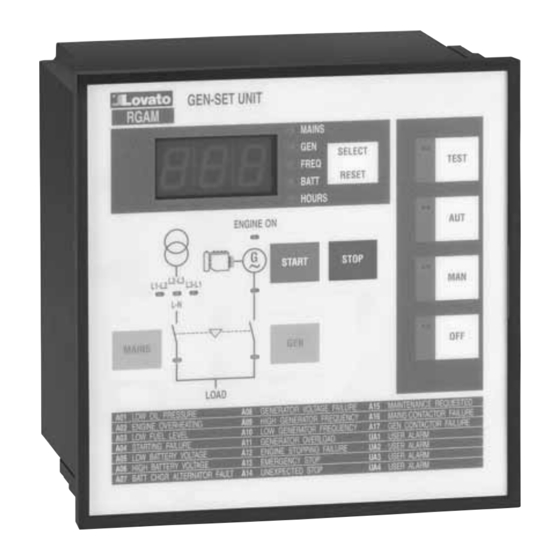
- Page 2 GENERALITÀ DESCRIPTION L’unità di controllo RGAM, è un apparecchio in grado di effettuare le The digital control unit RGAM is a device able to conduct RMS misure delle tensioni RMS e un controllo accurato e tempestivo di voltage reading and accurate timely controls of all the necessary tutte le funzioni necessarie al funzionamento ottimale del gruppo functions, to obtain the optimum operation of the generating set.
- Page 3 AUTOMATIC MODE FUNZIONAMENTO AUTOMATICO – In modalità AUT, in assenza della tensione di rete dopo il ritardo – In AUT and in lack of mains voltage after the delay for mains assenza tensione rete si disattiva l’uscita teleruttore rete e inizia il voltage absence, the mains contactor output is de-energised and ciclo di avviamento del gruppo elettrogeno.
- Page 4 The mains questo caso il contatto del relè dovrà essere connesso all’ingresso voltage control disabled input of the RGAM unit can however be programmabile del morsetto 12. Tale ingresso dovrà essere used for voltage readouts.
- Page 5 – In case of alarm, the display indicates the alarm code, the meaning allarme il cui significato è indicato nella tabella sul frontale of which is given in the table on the RGAM front plate. dell’RGAM. – Depending on the alarm importance, this can trip the generating –...
- Page 6 FUNCTIONS FUNZIONI TEST AUTOMATICO AUTOMATIC TEST – Il test automatico può aver luogo se l’apparecchio è nella modalità – Automatic test can take place if the unit is in AUT mode and is AUT e se abilitato. enabled. – Il test automatico è una prova di avviamento del gruppo –...
- Page 7 1000 meters. sino a 31 RGAM. – Up to 31 RGAM units can be linked to the RS485 interface by – Il collegamento del PC alla rete RS485 si effettua mediante means of twisted-pair cables.
- Page 8 – Visualizzazione di dati, messaggi e degli allarmi con data ed – Display of data, messages and alarms with date and hour entry. ora. – Modem or GSM modem setup with the possibility of RGAM – Set-up del modem o modem GSM con la possibilità di abilitare “Autocall” function enabling.
- Page 9 A07 CHARGER ALTERNATOR FAILURE A07 CHARGER ALTERNATOR FAILURE (Avaria alternatore carica batteria) It is displayed when the engine is running, voltage and/or Si verifica quando con il motore in moto (presenza tensione e/o generator frequency present, but the battery-charger alternator frequenza del generatore) il segnale di alternatore carica- signal remains below started engine voltage threshold for 4 batteria rimane sotto la soglia tensione motore avviato per 4...
- Page 10 Nel caso perduri l’errore IE2, Inviare l’RGAM alla LOVATO per la riparazione previa autorizzazione. Internal error, incorrect parameters Alteration of parameter memory. Remove RGAM supply; resupply and check all parameters. In case the IE2 error persists, return the RGAM to LOVATO for repair; ask for authorisation beforehand.
- Page 11 INGRESSI E USCITE INPUTS AND OUTPUTS TABELLA INGRESSI (ALLARME E COMANDO) - INPUTS TABLE (ALARM AND CONTROL) MORSETTO FUNZIONE FUNZIONE FUNZIONE FUNZIONE IMPOSTAZIONE N° DEFAULT N° 0 ALTERNATIVA N° 1 ALTERNATIVA N° 2 N° TERMINAL FUNCTION DEFAULT ALTERNATIVE ALTERNATIVE SETTING N°...
- Page 12 PROGRAMMAZIONE PROGRAMMING – L’impostazione dei parametri avviene mediante l’accesso a tre diversi – The parameter setting is done by entering in to three different setup: setup base, setup esteso e setup allarmi utente. setups: basic setup, advanced setup and user alarm setup. –...
-
Page 13: Advanced Setup Table
TABELLA SETUP ESTESO ADVANCED SETUP TABLE PARAMETRO DESCRIZIONE RANGE DEFAULT IMPOSTAZIONE PARAMETER DESCRIPTION SETTING P.20 Controllo tensione rete trifase/monofase Controllo trifase = 0 Three/Single-phase mains voltage control Three-phase control = 0 Controllo monofase = 1 Single-phase control = 1 P.21 Tensione nominale Ue rete/generatore 100-480VAC 400VAC... - Page 14 PARAMETRO DESCRIZIONE RANGE DEFAULT IMPOSTAZIONE PARAMETER DESCRIPTION SETTING P.45 Livello di priorità per attivazione allarme globale Attivazione con qualsiasi allarme = 0 Priority level for common alarm enable Enable with any alarm whatsoever =0 Solo con allarmi di priorità 1 = 1 Only with level 1 priority alarms = 1 Solo con allarmi di priorità...
- Page 15 TABELLA SETUP ALLARMI UTENTE - USER’S ALARMS SETUP TABLE IMPOSTAZIONE - SETTING PARAMETRO FUNZIONE DESCRIZIONE RANGE UA1 PARAMETER FUNCTION DESCRIPTION P.x0 NA Normalmente aperto Ingresso attivo alla chiusura del contatto Normally open NO Energised input at contact closing NC Normalmente chiuso Ingresso attivo alla apertura del contatto Normally closed NC Energised input at contact opening...
- Page 16 CARATTERISTICHE TECNICHE TECHNICAL CHARACTERISTICS CIRCUITO DI ALIMENTAZIONE - SUPPLY CIRCUIT Alimentazione da batteria (Us) 12VDC o 24VDC Battery supply (Us) 12VDC or 24VDC Corrente massima assorbita ≈160mA (250mA con RS485) Maximum current consumption ≈160mA (250mA with RS485) Corrente di stand-by ≈110mA (200mA con RS485) Stand-by current ≈110mA (200mA with RS485)
- Page 17 CARATTERISTICHE TECNICHE TECHNICAL CHARACTERISTICS CONTATTI DEI RELE DI USCITA AD ESCLUSIONE RETE, OUTPUT RELAY CONTACTS TO EXCLUDE MAINS, GENERATORE E SIRENA GENERATOR AND AUDIBLE ALARM Composizione contatti 1 contatto NA Contact arrangement 1 NO contact Tensione nominale d’impiego 24VDC Rated operational voltage 24VDC Tensioni massima d’impiego 30VDC...
-
Page 18: Normative Di Riferimento
NORMATIVE DI RIFERIMENTO REFERENCE STANDARDS – Prove dielettriche (IEC/EN 60255-5) – Dielectric test (IEC/EN 60255-5) Alla frequenza industriale (50 Hz): 2,5 kV per 1 min; Industrial frequency (50Hz): 2.5kV for one minute Impulsiva (1,2/50ms): 5 kV (3 positivi e 3 negativi ad intervalli Impulse (1.2/50ms): 5kV (3 positive and 3 negative at intervals superiori di 5 s). -
Page 19: Schemi Di Collegamento
SCHEMI DI COLLEGAMENTO WIRING DIAGRAMS SCHEMA COLLEGAMENTO PER GRUPPI ELETTROGENI CON ALTERNATORE CARICA BATTERIA PREECCITATO WIRING DIAGRAM FOR GENERATING SETS WITH PRE-ENERGISED BATTERY CHARGER ALTERNATOR CONNESSIONI PER CONTROLLO RETE TRIFASE CONNESSIONI PER CONTROLLO RETE MONOFASE WIRING FOR THREE-PHASE MAINS CONTROL WIRING FOR SINGLE-PHASE MAINS CONTROL 15 16 17 18 19 20 21 22 6 10 11 12 13... -
Page 20: Dimensions (Mm)
CONNESSIONI MORSETTIERA RGAM RGAM TERMINAL BLOCK CONNECTIONS Network Contactor Network Generator Contactor Generator Generator Common Contactor Alarm Network RS232 Contactor Generator + Battery Overload Supply Remote Slow Running Start Battery Charger Emerg. Permanent Mag. Alt. Start Stop Fuel Acoustic +D Battery Charger...
Need help?
Do you have a question about the RGAM and is the answer not in the manual?
Questions and answers