Table of Contents
Advertisement
Quick Links
Advertisement
Table of Contents

Related Manuals for Grantech SYS86351V4GA


Summary of Contents for Grantech SYS86351V4GA
- Page 1 SYS86351V4GA User's Manual Ver 1.0...
-
Page 2: Table Of Contents
Contents 1. Models and Attentions ....................2 1.1 Models ............................2 1.2 Attentions ............................2 2. Specification ........................3 3. Functional Block Diagram ....................5 4. Mechanical Drawing ...................... 6 5. Jumpers / Headers and Connectors ................7 6. Definition of Jumpers /Headers and Connectors ............10 F_AUDIO1 (Front Audio Header 5*2 Pin 2.54mm) .............. -
Page 3: Models And Attentions
Chipset PCIE HDMI PCIE mSATA SYS86351V4GA 3G/4G 1.2 Attentions 1) Notes under a table or figure indicate the difference of models, or alternative definition of specific pin of the header (jumper/connector). 2) How to identify the first pin of a header or jumper ... -
Page 4: Specification
2. Specification SYS86351V4GA Model ® Support 4 Generation Intel Core /Pentium /Celeron Processors, LGA1150 Support MAX CPU TDP: 84W ® Chipset Intel H81, TDP 4.1W 1 * HDMI (TYPE-A): Support max resolution up to 1920x1200@60Hz Display 1 * VGA (DB15/F): Support max resolution up to 1920x1200@60Hz... - Page 5 Notes: *: PCI-E 16x Gold Finger needs to be used with the Seavo customized daughter card. [1]: Intel® H81 support two independent displays. [2]: Mini PCI-E Slot support mSATA + 3G/4G by default. It also can support WIFI + 3G/4G. WIFI(PCIE) signal colay with 2 PCIE(PCIEx4).
-
Page 6: Functional Block Diagram
3. Functional Block Diagram VGA DB9FM Gen Intel® DIMMA DDR3 Haswell U-DIMM Desktop HDMI TYPE-A Processor DIMMB DDR3 Families U-DIMM PCIE x16 Port USB3.0*2 + USB2.0*2 Dual-USB3.0 USB2.0*1 TYPE-A PCIE*2(B85/Q87) PCIE x4 Gold finger PCIE*1 USB2.0*2 Dual-USB2.0 PCIE*1 TYPE-A(+RJ45) SATA3.0*1 USB2.0*2 Mini-PCIE Dual-USB2.0... -
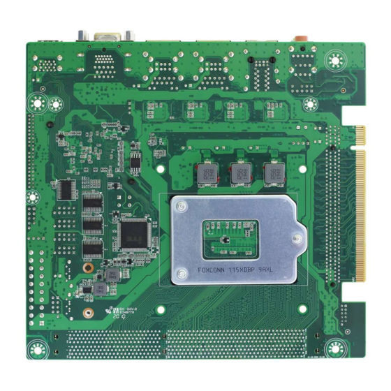
Page 7: Mechanical Drawing
4. Mechanical Drawing... -
Page 8: Jumpers / Headers And Connectors
5. Jumpers / Headers and Connectors... -
Page 9: F_Audio1 (Front Audio Header 5*2 Pin 2.54Mm)
Jumpers / Headers and Connectors F_AUDIO1 Front Audio Header (Line-Out + MIC) CPU_FAN1 CPU FAN Header J_GPIO1 GPIO Header F_PANEL1 Front Panel Header J_COM1/2/3/4 COM1/2/3/4 Header SYS_FAN1 System FAN Header F_USB1 Front USB2.0 Header J_RIO1 EXT-CARD Header CLR_CMOS1 CMOS Clear Jumper PCIEX16_1 PCI-E 16x Slot PCIEX16_GF1... -
Page 10: Atx1 (Atx 4P Cpu Power Input Connector)
SATA2 SATA2.0 7P Connector SATA1 SATA3.0 7P Connector ATX2 ATX 20P Power Input Connector ATX1 ATX 4P CPU Power Input Connector VGA_HDMI1(VGA) VGA DB15/F Connector RJ45_USB2(RJ45_2) GBE LAN RJ45 Connector2 RJ45_USB1(RJ45_1) GBE LAN RJ45 Connector1 RJ45_3-4(RJ45_3) GBE LAN RJ45 Connector3 USB1 Dual USB3.0 TYPE-A Connector VGA_HDMI1(HDMI) - Page 11 6. Definition of Jumpers /Headers and Connectors 1) F_AUDIO1 (Front Audio Header 5*2 Pin 2.54mm) Graphic Definition Definition MIC_IN_L MIC_IN_R + 3.3V AUD_OUT_R MIC_IN_DET AUD_OUT_L AUD_OUT_DET 2) CPU_FAN1 (CPU FAN Header 4*1 Pin 2.54mm) Graphic Definition Definition FAN Speed Detection1 + 12V FAN Speed Control1 3) J_GPIO1 (GPIO Header 6*2 Pin 2.00mm)
- Page 12 4) F_PANEL1 (Front Panel Header 5*2 Pin 2.54mm) Graphic Definition Definition HD LED+ Power LED+ HD LED- Power LED- RESET- Power+ RESET+ Power- 5) J_COM1/2/3/4 (COM1/2/3/4 Header 5*2 Pin 2.54mm) Graphic Definition Definition DCD#1 DSR#1 RXD1 RTS#1 TXD1 CTS#1 DTR#1 COM1_PIN8 J_COM1 DCD#2...
- Page 13 6) SYS_FAN1 (System FAN Header 4*1 Pin 2.54mm) Graphic Definition Definition FAN Speed Detection2 + 12V FAN Speed Control2 7) F_USB1 (Front USB2.0 Header 5*2 Pin 2.54mm) Graphic Definition Definition + 5V + 5V HUB_USB2_1- HUB_USB2_2- HUB_USB2_1+ HUB_USB2_2+ 8) J_RIO1 (EXT-CARD Header 20*2 Pin 2.00mm) Graphic Definition Definition...
-
Page 14: Rj45_Usb2(Rj45_2) (Gbe Lan Rj45 Connector2 8Pin)
+ 5V BUF_RST# + 5V CLK33M_SIO2 + 3.3V + 3.3V + 5VA SERIRQ 9) CLR_CMOS1 (CMOS Clear Jumper 3*1 Pin 2.54mm) Graphic Setting Function 1-2 (Default) Normal Clear CMOS 19) ATX1 (ATX 4P CPU Power Input Connector) Graphic Definition Definition +12V_CPU +12V_CPU 21) RJ45_USB2(RJ45_2) (GBE LAN RJ45 Connector2 8Pin) -
Page 15: Rj45_Usb1(Rj45_1) (Gbe Lan Rj45 Connector1 8Pin)
22) RJ45_USB1(RJ45_1) (GBE LAN RJ45 Connector1 8Pin) Graphic Definition Definition MDI1_0+ MDI1_2+ MDI1_0- MDI1_2- MDI1_1+ MDI1_3+ MDI1_1- MDI1_3- 1000M: Turn Orange ACT: Twinkling Yellow Speed Active 100M: Turn Green Only LINK: Lights On 10M: Lights Off Stop: Lights Off 23) RJ45_3-4(RJ45_3) (GBE LAN RJ45 Connector3 8Pin) Graphic Definition Definition... -
Page 16: Audio1 (Line-Out + Mic + Line-In 3.5Mm Jack)
29) AUDIO1 (Line-Out + MIC + Line-In 3.5mm Jack) Graphic Setting Function Blue Line-In Green Line-Out Pink MIC-In... -
Page 17: Bios Setup
7. BIOS setup See “BIOS Spec for SYS86351V4GA Series” for detail information of BIOS setup. 【End】...
Need help?
Do you have a question about the SYS86351V4GA and is the answer not in the manual?
Questions and answers