Advertisement
Quick Links
Advertisement

Related Manuals for Grantech SYS76989VGGA


Summary of Contents for Grantech SYS76989VGGA
- Page 1 SYS76989VGGA Industrial Computer Board...
- Page 2 Chapter 1 Overview Based on the innovative Intel QM77 chipsets for op- ® timal system efficiency, the board accommodates the Intel Core™ i7 / i5 / i3 or Celeron proces- ® ® sor in rPGA-989 (Socket G2) and supports 2 DDR3 1066/1333/1600 SO-DIMM slots to provide the maxi- mum of 32GB memory capacity.
- Page 3 ▍ Overview Motherboard Specifications ■ Intel Core™ i7 / i5 / i3 or Celeron processor in ® ® rPGA-989 (Socket G2) Chipset ■ Intel QM77 / HM76 Chipset ® ■ Memory 2 unbuffered non-ECC DDR3 1066/1333/1600 SO-DIMM slots ■ Supports the maximum of 16GB ■...
- Page 4 ■ Slot 2 Mini-PCIe slots (including 1 x mSATA function) Form Factor ■ Mini-ITX: 17.0cm x 17.0cm ■ Power Solution: 12 Environ- ■ Operating Temperature: -10 C to 60 Humidity: 30% ~ 80% RH, Non-Condensing mental Office and similar emvironment, no corrosive ■...
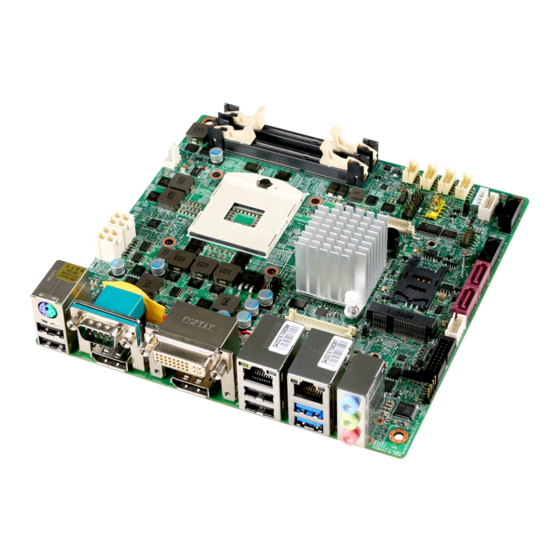
- Page 5 ▍ Overview Motherboard Layout Backlight Pinheader & LVDS Connector LVDS Jumper CPU Fan Connector DC Power System Fan Connector COM Port Connector Jumper CPU Socket Back Panel SO-DIMM Slots Clear CMOS Jumper COM Port Jumper USB 2.0 Connector COM Port Connector AT/ ATX Jumper HDD Power...
- Page 6 Chapter 2 Hardware Setup This chapter provides you with the information on motherboard hardware configurations. Incorrect set- ting of jumpers and connectors may damage your motherboard. Please pay special attention not to con- nect these headers in wrong direction. DO NOT adjust any jumper while the motherboard is powered on.
- Page 7 ▍ Hardware Setup Quick Components Guide JLCD1, p.2-16 JLVDS1, p.2-14 CPUFAN1, p.2-9 DCPWR1/2, SYSFAN1, p.2-9 JCOMP1, p.2-6 p.2-16 CPU, p.2-3 Back Panel, p.2-7 DIMM1/2, p.2-5 JCMOS1, p.2-15 JCOMP2, p.2-16 JUSB1, p.2-13 COM2~4, p.2-12 JATX1, p.2-15 JPW1, p.2-6 SLOT1, p.2-17 JCASE1, p.2-10 SATA4, JSPDI1, SATA3,...
- Page 8 CPU (Central Processing Unit) When you are installing the CPU, make sure that you install the cooler to prevent overheating. If you do not have the CPU cooler, consult your dealer before turning on the computer. Important Overheating Overheating can seriously damage the CPU and motherboard. Always make sure the cooling fans work properly to protect the CPU from over- heating.
- Page 9 ▍ Hardware Setup CPU Installation Locate the CPU socket on the motherboard. On the upper end of the CPU socket is a socket actuator in the form of a slotted screw head. To install the CPU, follow the steps shown below: 1.
- Page 10 Memory These DIMM slots are intended for memory modules. 1. Unlock the DIMM slot by flipping open its side clips. Vertically insert the DIMM into the DIMM slot. The DIMM has an off-center notch at the bottom that will only allow it to fit one way into the DIMM slot.
- Page 11 ▍ Hardware Setup Power Supply 4-pin Power Connector: DCPWR1, DCPWR2 These connectors are used to provide power to the motherboard. HDD Power Connector: JPW1, JPW2 This connector is used to provide power for hard disk drives. Important Make sure that all the connectors are connected to proper power supplies to ensure stable operation of the motherboard.
- Page 12 Back Panel I/O Keyboard / Mouse DVI-I Port Ports Combo Port Serial Port Line-In Line-Out USB 2.0 DisplayPort DisplayPort USB 2.0 USB 3.0 Ports Ports Ports ▶ Keyboard / Mouse Combo Port The standard PS/2 mouse/keyboard DIN connector is for a PS/2 ®...
- Page 13 ▍ Hardware Setup ▶ USB 3�0 Port The USB 3.0 port is backward-compatible with USB 2.0 devices and sup- ports data transfer rate up to 5 Gbit/s (SuperSpeed). ▶ LAN Port The standard RJ-45 LAN jack is for connection to the Local Area Network (LAN).
- Page 14 Connector Serial ATA Connector: SATA1 ~ SATA4 This connector is a high-speed Serial ATA interface port. Each connector can connect to one Serial ATA device. Chip SATA 6 Gb/s SATA 3 Gb/s Intel QM77 SATA1, SATA2 SATA3, SATA4 Important Please do not fold the Serial ATA cable into a 90-degree angle. Other- wise, data loss may occur during transmission.
- Page 15 ▍ Hardware Setup Chassis Intrusion Pinheader: JCASE1 This connector connects to the chassis intrusion switch cable. If the com- puter case is opened, the chassis intrusion mechanism will be activated. The system will record this intrusion and a warning message will flash on screen.
- Page 16 Audio Amplifier Pinheader: JAMP1 The JAMP1 is used to connect audio amplifiers to enhance audio per- formance. S/PDIF Pinheader: JSPDI1 This pinheader is used to connect S/PDIF (Sony & Philips Digital Inter- connect Format) interface for digital audio transmission. GPIO Pinheader: JGPIO1 This connector is provided for the General-Purpose Input/Output (GPIO) peripheral module.
- Page 17 ▍ Hardware Setup Serial Port Connector: COM2, COM3, COM4 This connector is a 16550A high speed communications port that sends/ receives 16 bytes FIFOs. You can attach serial devices to it through the optional serial port bracket. RS-232 SIGNAL DESCRIPTION Data Carrier Detect Receive Data Transmit Data...
- Page 18 Front USB 2�0 Connector: JUSB1 This connector, compliant with Intel I/O Connectivity Design Guide, is ideal for connecting high-speed USB interface peripherals such as USB HDD, digital cameras, MP3 players, printers, modems and the like. Important Note that the pins of VCC and GND must be connected correctly to avoid possible damage.
- Page 19 ▍ Hardware Setup LVDS Flat Panel Connector: JLVDS1 The LVDS (Low Voltage Differential Signal) connector provides a digital interface typically used with flat panels. After connecting an LVDS inter- faced flat panel to the JLVDS1, be sure to check the panel datasheet and set the J2 jumper for proper power voltage.
- Page 20 Jumper Clear CMOS Jumper: JCMOS1 There is a CMOS RAM onboard that has a power supply from an external battery to keep the data of system configuration. With the CMOS RAM, the system can automatically boot OS every time it is turned on. If you want to clear the system configuration, set the jumper to clear data.
- Page 21 ▍ Hardware Setup Serial Port Power Jumper: JCOMP1, JCOMP2 These jumpers specify the operation voltage of the onboard serial ports. +12V JCOMP1 JCOMP2 +12V Backlight Header & LVDS Power Jumper: JLCD1 The backlight connector is provided for LCD backlight options while the LVDS power jumper allows users to select the operation voltage of the LVDS flat panel.
- Page 22 Slot Mini-PCIe (Peripheral Component Interconnect Express) Slot The Mini-PCIe slot is provided for wireless LAN card, TV tuner card, Rob- son NAND Flash card and mSATA devices. Important When adding or removing expansion cards, make sure that you unplug the power supply first. Meanwhile, read the documentation for the expan- sion card to configure any necessary hardware or software settings for the expansion card, such as jumpers, switches or BIOS configuration.
Need help?
Do you have a question about the SYS76989VGGA and is the answer not in the manual?
Questions and answers