Table of Contents
Advertisement
Quick Links
Advertisement
Table of Contents

Related Manuals for Grantech SYS86355VGGA-6


Summary of Contents for Grantech SYS86355VGGA-6
- Page 1 SYS86355VGGA-6 C User Manual Revision: 1.0 Release date: April 27, 2020 Trademark: * Specifications and Information contained in this documentation are furnished for information use only, and are subject to change at any time without notice, and should not be construed as a commitment by...
- Page 2 Environmental Protection Announcement Do not dispose this electronic device into the trash while discarding. To minimize pollution and ensure environment protection of mother earth, please recycle.
-
Page 3: Table Of Contents
TABLE OF CONTENT ENVIRONMENTAL SAFETY INSTRUCTION ................iii USER’S NOTICE ........................iv MANUAL REVISION INFORMATION ..................iv ITEM CHECKLIST ........................iv CHAPTER 1 INTRODUCTION OF THE MOTHERBOARD PRODUCT FEATURES ....................1 SPECIFICATION ......................2 MAIN BOARD DIAGRAM ...................3 CHAPTER 2 HARDWARE INSTALLATION LOCATION OF INTERNAL JUMPER AND CONNECTOR ........5 INTERNAL JUMPER AND CONNECTOR SETTING ..........6 2-2-1 CONNECTORS .....................9... -
Page 4: Environmental Safety Instruction
Environmental Safety Instruction Avoid the dusty, humidity and temperature extremes. Do not place the product in any area where it may become wet. 0 to 60 centigrade is the suitable temperature. (The figure comes from the request of the main chipset) ... -
Page 5: User's Notice
USER’S NOTICE COPYRIGHT OF THIS MANUAL BELONGS TO THE MANUFACTURER. NO PART OF THIS MANUAL, INCLUDING THE PRODUCTS AND SOFTWARE DESCRIBED IN IT MAY BE REPRODUCED, TRANSMITTED OR TRANSLATED INTO ANY LANGUAGE IN ANY FORM OR BY ANY MEANS WITHOUT WRITTEN PERMISSION OF THE MANUFACTURER. -
Page 6: Chapter 1 Introduction Of The Motherboard
Chapter 1 Introduction of the Motherboard Product Features Intel ® LGA 1150 Socket Core i7/i5/i3/Pentium Processor Support 2 x DDR3 /DDR3L 1600/1333Mhz SO-DIMM up to 16GB 2 x Intel ® i211AT Gigabit Ethernet 4 x USB3.0 (PCI-E to USB3.0), 8 x USB2.0 ... -
Page 7: Specification
1-2 Specification Spec Description Intel ® LGA 1150 Socket Core i7/i5/i3/Pentium Processor Memory 2* DDR3/DDR3L 1600/1333MHz SO-DIMM slot up to 16GB 2* Full-size Mini PCIe slot (MINI_CARD Co-lay MSATA) Expansion Slot 1 * PCIex16 Slot 1* SIM Card socket ... -
Page 8: Main Board Diagram
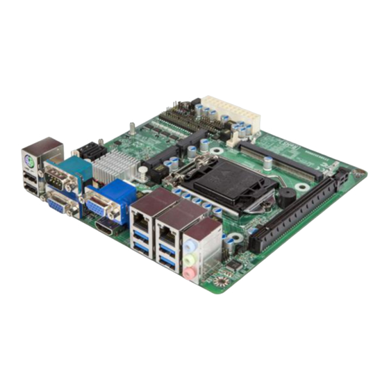
1-3 Main Board Diagram: Front SATAIII Ports (SATA1/2) Top/Middle: USB2.0 JW_FP Bottom: Header HDMI Mini-PCIE/ mSATA Slot Top: COM1 Mini-PCIe Slot Bottom: VGA1 ATXPWR Connector ATX12V SYSFAN1 Header Connector Top: Intel CPU COM2 Socket Bottom: VGA2 Top: RJ-45 LAN Port1 Middle/Bottom: USB3.0 Ports SIM Card... - Page 9 Main Board Diagram: Back SODIMM2...
-
Page 10: Chapter 2 Hardware Installation
Chapter 2 Hardware Installation 2-1 Location of Internal Jumper and Connector PS2_CON1 COM5-COM6 TPM1 SATAIII Ports COM4 (SATA1/2) JPCOM3 COM3_SEL PS2_VCC Top/Middle: CASE_OPEN USB2.0 JW_FP Bottom: COM3 JPCOM4 Header HDMI JBAT F_USB3 F_USB2 GPIO_CON F_USB1 Top: COM4_SEL BATCON AT_ATX_MODE COM1 JPCOM1 Mini-PCIE/ mSATA Slot... -
Page 11: Internal Jumper And Connector Setting
2-2 Internal Jumper and Connector Setting (1) JPCOM1/3/4 (4-pin): COM1/3/4 Port Pin9 Function Select JPCOM3 JPCOM4 JPCOM1 2-4 Closed: 3-4 Closed: 4-6 Closed: RING (Default); 12V. JPCOM2 (2) JPCOM2 (4-pin): COM2 Port Pin9 Function Select JPCOM3 JPCOM4 JPCOM1 4-6 Closed: 2-4 Closed: 3-4 Closed: 12V. - Page 12 (3) PS2_VCC (3-pin): PS2_CON1 VCC 5V/5VSB Select PS2_VCC 1-2 Close: 2-3 Close: 5V (Default); 5VSB. (4) JBAT (3-pin): Clear CMOS Setting JBAT 1-2 Close: 2-3 Close: 5V (Default); 5VSB.
- Page 13 (5) AT_ATX_MODE (3-pin): AT_ATX_MODE Select 1-2 Close: 2-3 Close: 5V (Default); 5VSB. AT_ATX_MODE *ATX Mode Selected: Press power button to power on after power input ready; AT Mode Selected: Directly power on as power input ready. (6) CASE_OPEN (2-pin): Case Open Message Display Function Select CASE_OPEN 1-2 Open:...
-
Page 14: Connectors
JP3 (6-pin) &JP4 (6-pin): MINI_CARD Slot Mini-PCIE/MSATA Function Select JP3&JP4 → MINI_CARD Function Select → ← (1-3) & (2-4) Closed: MINI_CARD functions as MSATA interface. → ← (3-5) & (4-6) Closed: MINI_CARD functions as Mini-PCIE Slot. 2-2-1 Connectors (1) Rear I/O Connectors RJ-45 RJ-45 COM2... - Page 15 Icon Name Function To connect USB keyboard, mouse or other USB 2.0 Port devices compatible with USB specification. To connect display device that support HDMI HDMI Port specification. Mainly for user to connect external MODEM RS232/422/485 or other devices that supports COM Port Serial Communications Interface.
- Page 16 COM1/COM2 (9-pin Block): RS232/422/485 Serial Port RS422 RX(B) RS422 RX(A) RS422 TX(A) RS485 D+(A) RS422 TX(B) RS485 D-(B) For RS422 Mode For RS485 Mode COM1/COM2 port can function as RS232/422/485 serial port. In normal settings COM1/2 functions as RS232 port. With compatible COM cable COM1/2 can function as RS422 or RS 485 port.
- Page 17 ATX12V (4-pin block): ATX12V Type Power Connector Pin1 Pin No. Definition ATX12V +12V +12V SATA1/2 (7-pin Block): SATAIII Port connector The board comes with SATA1 & SATA2 port that supports 6GB/s transfer rate. SATA2 Pin No. Definition SATA1 SYSFAN1 (3-pin): System Fan Header Pin1 SYSFAN1...
-
Page 18: Headers
CPUFAN (4-pin): CPUFAN Header CPUFAN Pin1 2-2-2 Headers (1) JW_FP (9-pin): Front Panel Header JW_FP PIN 1 (2) PS2_CON1 (6-pin): PS/2 Keyboard & Mouse Header PS2_CON1 Pin1... - Page 19 (3) LAN_LED (8-pin): LANLED Header LAN_LED Pin1 (4) SPEAK_CON (4-pin): 3W Amplifier Header Pin1 Pin No. Definition SPEAK_CON (5) F_USB1/2/3 (9-pin): USB 2.0 Port Header FP_USB1 Pin 1 FP_USB2 FP_USB3...
- Page 20 (6) TPM1 (20-pin): TPM Header TPM1 Pin 1 (7) GPIO_CON (10-pin): 8-bit GPIO Header Pin 1 GPIO_CON...
- Page 21 (8) COM3/4 (9-Pin): RS232 Serial Port Header COM3 COM4 Pin6 Pin1...
- Page 22 COM5-COM6 (20-Pin): RS232 Serial Port Header Block COM5 COM5~6 Pin 2 Pin 1 COM5-COM8 Pin NO. RS232 Pin NO. RS232 Pin 1 DCD5 Pin 2 DSR5 Pin3 SIN5 Pin 4 RTS5 SOUT5 CTS5 Pin 5 Pin 6 COM5 Pin 7 DTR5 Pin 8 Pin 9...
Need help?
Do you have a question about the SYS86355VGGA-6 and is the answer not in the manual?
Questions and answers