
Related Manuals for Stryker 738


Summary of Contents for Stryker 738
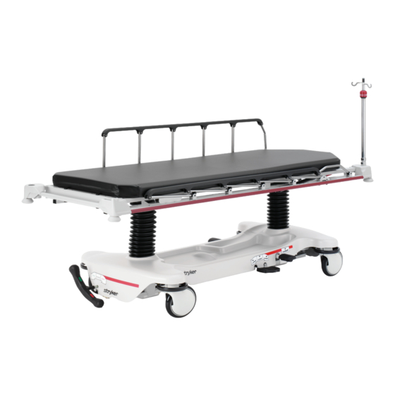
- Page 1 Wide Transport Stretcher Model 738 Maintenance Manual For Parts or Technical Assistance: USA: 1-800-327-0770 (option 2) Canada: 1-888-233-6888 2007/04 0738-009-002 REV B www.stryker.com...
-
Page 3: Table Of Contents
Non-Constant Descent Jack ............. . 40 www.stryker.com... - Page 4 International Warranty Clause ............. 81 0738-009-002 REV B www.stryker.com...
-
Page 5: Introduction
Introduction InTended USe This manual is designed to assist you with the maintenance of the Wide Transport Stretcher, Model 738. Carefully read this manual thoroughly before using the equipment or beginning maintenance on it. To ensure safe operation of this equipment, it is recommended that methods and procedures be established for educating and training staff on the safe operation of this stretcher. -
Page 6: Symbols
(Weee), this symbol indicates that the product must not be disposed of as unsorted municipal waste, but should be collected separately. Refer to your local distributor for return and/or collection systems available in your country. Return To Table of Contents 0738-009-002 REV B www.stryker.com... -
Page 7: Summary Of Safety Precautions
The hood may not be used for stepping. note • Clean hood storage area regularly. • The bottom of the brake rings should be cleaned regularly to prevent wax and/or floor remnant buildup. Return To Table of Contents www.stryker.com 0738-009-002 REV B... -
Page 8: Preventative Maintenance
Preventative maintenance should be performed at a minimum of annually. A preventative maintenance program should be established for all Stryker Medical equipment. Preventative maintenance may need to be performed more frequently based on the usage level of the product. -
Page 9: Cleaning
SoMe CLeanIng prodUCTS are CorroSIve In naTUre and May CaUSe daMage To The prodUCT If USed IMproperLy. If the products suggested above are used to clean Stryker patient care equipment, measures must be taken to insure the stretcher is wiped with a damp cloth soaked in clean water and thoroughly dried following cleaning. -
Page 10: Quick Reference Replacement Parts List
The parts and accessories listed on this page are all currently available for purchase. Some of the parts identified on the assembly drawing parts in this manual may not be individually available for purchase. Please call Stryker Customer Service USA: 1-800-327-0770 (Option 2), Canada: 1-888-233-6888 for availability and pricing. -
Page 11: Service Information
Using the brake ring, lift up on the base assembly and pull the caster assembly down to remove it. Reverse steps 1-3 to install the new caster. Return To Table of Contents www.stryker.com 0738-009-002 REV B... -
Page 12: Brake Rod Removal
5-13 ft. - lbs. CaUTIon When reattaching the brake rod assembly to the base frame, set the torque specs no higher than 13 ft. - lbs. or damage could occur to the bolts. Return To Table of Contents 0738-009-002 REV B www.stryker.com... - Page 13 5-13 ft. - lbs. CaUTIon When reattaching the brake rod assembly to the base frame, set the torque specs no higher than 13 ft. - lbs. or damage could occur to the bolts. Return To Table of Contents www.stryker.com 0738-009-002 REV B...
-
Page 14: Release Pedal Adjustment
Dislodge the side control release pedal swivels from the studs on the side control release pedal weldment. Remove the foot end pedal release rods. Reverse steps 1 - 5 to reinstall the pedal rods. Return To Table of Contents 0738-009-002 REV B www.stryker.com... -
Page 15: Fifth Wheel Assembly Removal
5 - 13 ft. - lbs. CaUTIon When reattaching the fifth wheel assembly to the base frame, set the torque specs no higher than 13 ft. - lbs. or dam- age could occur to the bolts. Return To Table of Contents www.stryker.com 0738-009-002 REV B... -
Page 16: Litter Top Removal
Verify all hydraulic linkages are secure and operating properly. Using the pump pedal, actuate the system several times to force the air through the system. The jack should now raise properly. Return To Table of Contents 0738-009-002 REV B www.stryker.com... -
Page 17: Foot End Hydraulic Jack Removal (Base With Dual Controls)
Remove the two hex washer head screws holding the reservoir clamp. Remove the jack assembly. Reverse steps 1 - 7 to install the new jack. note The jack descent rate is preset at the factory and adjustment is not recommended. Return To Table of Contents www.stryker.com 0738-009-002 REV B... -
Page 18: Pneumatic Fowler Adjustment
Too little “play” will obstruct the latch and keep it from engaging completely in the full up position, which may result in damage to the latch and/or injury to the patient or user Return To Table of Contents 0738-009-002 REV B www.stryker.com... -
Page 19: Assembly Drawings
5 Wheel Base assembly - 0853-006-110 Item part no. part name Qty. 0023-288-000 Hex Washer Head Screw 0023-305-000 Hex Head Cap Screw 0753-006-148 Cam Bearing 0853-006-130 Fifth Wheel Assembly Return To Table of Contents www.stryker.com 0738-009-002 REV B... - Page 20 Wheel assembly - 0853-006-130 Return To Table of Contents 0738-009-002 REV B www.stryker.com...
-
Page 21: Fifth Wheel Assembly - 0853-006-130
Wheel Ramp 0753-006-152 Spring Spacer 0753-006-153 Roller Stem 0753-006-198 Drive Pin 0753-006-223 Drive Shaft 0753-006-277 Roller 0853-006-126 Wheel Bracket 0853-006-131 Wheel Weldment 0853-006-227 Return Spring Hook 0853-010-045 Hood Standoff 1210-001-147 Wheel Return To Table of Contents www.stryker.com 0738-009-002 REV B... -
Page 22: Standard Brake Assembly (Fifth Wheel Base)
Standard Brake assembly (fifth Wheel Base) For Reference Only: 0853-003-205 Return To Table of Contents 0738-009-002 REV B www.stryker.com... - Page 23 Clevis Pin 0753-003-079 Caster Tube Brake Pin Guide 0753-003-121 Brake Cushion 0853-003-230 Bearing Pivot Support 0853-001-001 Base Weldment 0853-003-201 Brake Rod Assembly 0853-005-087 Return Spring Hook 3001-200-052 Ground Chain 0753-003-131 Spacer Return To Table of Contents www.stryker.com 0738-009-002 REV B...
-
Page 24: Brake Rod Assembly
Rue Ring Cotter 0753-003-015 Brake Rod Nyliner 0853-003-004 Brake Rod Support 0853-003-010 Drive Link Assembly (pg. 25) 0853-003-014 Brake Rod 0853-006-135 Drive Link Assembly 1210-201-335 Red Brake Label 1210-201-336 Green Steer Label Return To Table of Contents 0738-009-002 REV B www.stryker.com... -
Page 25: Drive Link Assembly - 0853-003-010
Link assembly - 0853-003-010 Item part no. part name Qty. 0753-003-098 Flat Head Semi Tubular Rivet 0753-203-102 Brake Cam 0853-003-011 Brake Rod Drive Link 0853-003-061 Brake Cam Drive Link Return To Table of Contents www.stryker.com 0738-009-002 REV B... -
Page 26: Drive Link Assembly - 0853-006-135
Link assembly - 0853-006-135 Item part no. part name Qty. 0753-003-098 Semi Tubular Rivet 0853-003-011 Brake Rod Drive Link 0853-006-022 Wheel Cam Drive Link 0853-006-047 Wheel Cam Drive Link Return To Table of Contents 0738-009-002 REV B www.stryker.com... -
Page 27: 8" Caster Assembly - 0753-010-220
8” Caster assembly - 0753-010-220 Item part no. part name Qty. 0003-099-000 Hexagonal Head Cap Screw 0016-060-000 Center lock Nut 0753-003-215 Wheel 0753-010-021 Caster Horn W/Bearing Return To Table of Contents www.stryker.com 0738-009-002 REV B... -
Page 28: Side Control Brake Assembly
Side Control Brake assembly For Reference Only: 0853-003-220 Return To Table of Contents 0738-009-002 REV B www.stryker.com... - Page 29 Side Control Brake assembly See Detail A detail a Typical Both ends Return To Table of Contents www.stryker.com 0738-009-002 REV B...
- Page 30 Brake Cushion 0853-003-230 Bearing Pivot Support 0853-001-001 Base Weldment 0853-003-210 Side Control Brake Ass’y (pg. 32 0853-003-225 Brake Rod/Side Cntrl Ass’y (pg.31) 0853-005-087 Return Spring Hook 3001-200-052 Ground Chain 0753-003-131 Spacer Return To Table of Contents 0738-009-002 REV B www.stryker.com...
-
Page 31: Brake Rod / Side Control Assembly
0753-003-112 Side Control Link 0753-003-004 Brake Rod Support 0853-003-010 Drive Link Assembly (pg. 25) 0853-003-014 Brake Rod 0853-006-135 Drive Link Assembly (pg. 26) 1210-201-335 Red Brake Label 1210-201-336 Green Steer Label Return To Table of Contents www.stryker.com 0738-009-002 REV B... -
Page 32: Side Control Brake Sub - Assembly
Clevis Pin 0027-020-000 Rue Ring Cotter 0753-003-112 Side Control Link 0753-003-117 Rod End Link 0853-003-214 Side Control Shaft Support 0853-003-319 Side Control Brake Rod 1210-201-335 Red Brake Label 1210-201-336 Green Steer Label Return To Table of Contents 0738-009-002 REV B www.stryker.com... -
Page 33: Standard Brake Assembly, Colored Components
For Reference Only: 0853-003-630 part number part description Quantity 0753-003-128 Brake Ring Weldment (Black) 0753-010-020 8” Caster Assembly (Black) 0753-201-126 Pump Pedal (Black) 0853-005-154 Butterfly “V” Pedal (Black) 1061-201-127 Short Uni-Pedal (Black) Return To Table of Contents www.stryker.com 0738-009-002 REV B... -
Page 34: Dual Sided Hydraulics Assembly (Fifth Wheel Base)
Sided hydraulics assembly (fifth Wheel Base) For Reference Only: 0853-005-525 Return To Table of Contents 0738-009-002 REV B www.stryker.com... - Page 35 Sided hydraulics assembly (fifth Wheel Base) See Detail A detail a Return To Table of Contents www.stryker.com 0738-009-002 REV B...
- Page 36 Foot End Release Rod 0853-004-251 Lowering Pedal Assembly (pg. 38) 0853-005-035 Pump Connecting Tube Weldment 0853-005-074 Pivot Pin 0853-005-075 Pump Pedal Link 0853-005-285 HE Pump Pedal Assembly (pg. 39) 0853-010-215 Release Rod Bracket Return To Table of Contents 0738-009-002 REV B www.stryker.com...
-
Page 37: Standard Hydraulics Assembly, Colored Components
Quantity 0753-004-134 Left Foot End Release Pedal (Black) 0753-004-135 Right Foot End Release Pedal (Black) 0753-201-126 Pump Pedal (Black) 0853-003-099 Butterfly “V” Pedal (Black) 1061-201-127 Short Uni-Pedal (Black) Return To Table of Contents www.stryker.com 0738-009-002 REV B... -
Page 38: Lowering Pedal Assembly - 0853-004-251
(See Page 37) Standard Hydraulics Assembly, Colored Components Item part no. part name Qty. 0025-133-000 Rivet 0753-004-029 Release Pedal Standoff 0853-004-004 Release Pedal Weldment 0853-004-320 Release Pedal Support 1069-004-320 Release Pedal Support Return To Table of Contents 0738-009-002 REV B www.stryker.com... -
Page 39: Head End Pump Pedal Assembly - 0853-005-285
- 0853-005-285 (See Page 37) Standard Hydraulics Assembly, Colored Components Item part no. part name Qty. 0026-343-000 Groove Pin 0715-001-140 Vinyl Tube 0853-005-180 Head End Pump Pedal Weldment Return To Table of Contents www.stryker.com 0738-009-002 REV B... -
Page 40: Non-Constant Descent Jack
For Reference Only: 0853-002-180 Item part no. part name Qty. 0023-288-000 Hexagonal Washer Head Screw 0753-002-170 Jack Assembly, Non-Constant Descent (pg. 41) 0853-010-007 Reservoir Clamp Return To Table of Contents 0738-009-002 REV B www.stryker.com... -
Page 41: Non-Constant Jack Assembly - 0753-002-170
0048-190-000 U - Cup Seal 0753-002-017 Jack Cap 0753-002-075 Jack Base Assembly, Non-Constant Descent (pg. 42) 0753-002-104 Actuator Rod Assembly 0753-002-106 Actuator Cylinder Assembly 0753-102-129 Reservoir Tube 0753-202-115 Jack Assembly Label Return To Table of Contents www.stryker.com 0738-009-002 REV B... -
Page 42: Jack Base Assembly, Variable Descent Jack
Conical Compression Spring 0715-001-341 Poppet 0753-002-003 Pump Ram Assembly 0753-002-010 Jack Base 0753-002-019 Valve Filter 0753-002-051 Plug Assembly 0753-002-052 Check Valve Assembly 0753-002-063 Standard Descent Valve Assembly 0753-002-065 Release Valve Assembly Return To Table of Contents 0738-009-002 REV B www.stryker.com... -
Page 43: Base Labeling Assembly, Standard Brakes
Label see Base Labeling, Colored Components Specification Label (Serial number Location) foot end head end Item part no. part name Qty. 0853-001-040 Base Hood 1040-010-134 Bellows 0946-201-060 Stryker Logo Label Return To Table of Contents www.stryker.com 0738-009-002 REV B... -
Page 44: Base Labeling Assembly, 4-Sided Brakes
Specification Label (Serial number Location) foot end head end Item part no. part name Qty. 0853-001-041 Base Hood 1040-010-134 Bellows 0946-201-060 Stryker Logo Label 0853-010-018 Brake/Steer Label, Right 0853-010-019 Brake/Steer Label, Left Return To Table of Contents 0738-009-002 REV B www.stryker.com... -
Page 45: Base Labeling, Colored Components
1010-900-230 Cath. Lab 1010-900-270 Extended Stay 1010-900-235 Same Day Surgery 1010-900-275 Maternity 1010-900-240 Cardiology 1010-900-280 Endoscopy 1010-900-245 Ultrasound 1010-900-285 Radiology 1010-900-250 note All base hood department labels are quantity of two. Return To Table of Contents www.stryker.com 0738-009-002 REV B... -
Page 46: Litter Assembly
Litter assembly For Reference Only: 0738-010-010 Return To Table of Contents 0738-009-002 REV B www.stryker.com... - Page 47 Litter assembly Return To Table of Contents www.stryker.com 0738-009-002 REV B...
- Page 48 Litter assembly Return To Table of Contents 0738-009-002 REV B www.stryker.com...
- Page 49 Hole Plug 0753-010-026 Support Tube 0753-010-030 Support Tube 0926-400-142 Bumper 0938-001-401 Collar 0946-001-060 Stryker Logo Label 1001-001-037 Jack Support Tube, HE 1001-040-012 Foot Board Receptacle 1001-201-029 Nylon Insert 1010-026-017 Siderail Assembly, Right (pg. 52) 1010-026-019 Siderail Assembly, Left (pg. 52)
-
Page 50: Fowler To Litter Assembly
Litter assembly For Reference Only: 0736-031-010 Return To Table of Contents 0738-009-002 REV B www.stryker.com... - Page 51 0016-117-000 Stover Hex Lock Nut 0023-256-000 Sheet Metal Screw 0025-050-000 Rivet 0721-031-065 Hole Plug 0736-031-120 Pneumatic Fowler Ass’y (pg. 53) 7900-001-102 Velcro Pile 9” 1010-031-078 Gas Cylinder 1211-031-031 Pneumatic Fowler Rest Return To Table of Contents www.stryker.com 0738-009-002 REV B...
-
Page 52: Siderail Assembly, Right & Left
(Left Side Shown) Item part no. part name Qty. 1010-026-015 Top Rail 1010-026-083 Upright 1010-026-084 Upright, Bent 1010-026-082 Spacer 0025-106-000 Semi-Tubular Rivet 1010-026-010 Round Hole Plug 1010-026-085 Upright, Latch 1010-026-012 Bent Spindle Stop Return To Table of Contents 0738-009-002 REV B www.stryker.com... -
Page 53: Pneumatic Fowler Assembly
Fiber Lock Nut 0025-120-000 Rivet 1001-001-036 Hole Plug 1210-031-106 Outer Housing Ass’y, Right (pg. 54) 1210-031-107 Outer Housing Ass’y, Left (pg. 54) 1501-031-013 Fowler Tube 1510-231-012 Fowler Skin 1710-031-118 Trip Bar Assembly Return To Table of Contents www.stryker.com 0738-009-002 REV B... -
Page 54: Pneumatic Fowler Outer Housing Assembly
Semi - Tubular Rivet 1210-031-103 Pivot Tab 1210-031-104 Outer Housing, Right For Reference Only: 1210-031-107 (Left) Item part no. part name Qty. 0025-144-000 Semi - Tubular Rivet 1210-031-103 Pivot Tab 1210-031-105 Outer Housing, Left Return To Table of Contents 0738-009-002 REV B www.stryker.com... -
Page 55: Optional Knee Gatch Assembly
For Reference Only: 0736-010-010 Return To Table of Contents www.stryker.com 0738-009-002 REV B... - Page 56 Return To Table of Contents 0738-009-002 REV B www.stryker.com...
- Page 57 Return To Table of Contents www.stryker.com 0738-009-002 REV B...
- Page 58 1501-034-023 Mid Section Support Assembly 1501-034-112 Calf Frame Weldment 1510-034-090 Slider Pad 1510-234-027 Mid Section Skin 1510-234-028 Thigh Section Skin 1510-234-126 Calf Section Skin 1550-034-021 Thigh Support 1550-090-034 Engage Gatch Label Return To Table of Contents 0738-009-002 REV B www.stryker.com...
-
Page 59: Optional Knee Gatch Crankscrew Assembly
Crankscrew assembly For Reference Only: 0736-046-010 Return To Table of Contents www.stryker.com 0738-009-002 REV B... - Page 60 Slotted Spring Pin 0081-174-000 Washer 0081-175-000 Washer 0081-176-000 Washer 0378-024-029 Shoulder Bolt 0938-001-175 Bearing Assembly 0938-001-177 Knob 0946-033-018 Crank Disc 1001-134-047 Knee Gatch Screw 1510-034-055 Gatch Drive Tube Assembly 1510-034-084 Screw Cover Assembly 1550-001-014 Magnet 1550-001-016 Crank Handle 0738-009-002 REV B www.stryker.com...
-
Page 61: Corner Cover, Assembly
For Reference Only: Part Number head end: 0736-035-010 foot end: 0736-035-060 HEAD END SHOWN Item part no. part name Qty. 0023-104-000 Tapping Screw 0037-059-000 Heyco Hole Plug 1010-201-238 Corner Cover/Slot 1010-201-239 Corner Cover/Hole Return To Table of Contents www.stryker.com 0738-009-002 REV B... -
Page 62: Corner Cover, Push Handle Assembly
Hex Head Cap Screw 0003-050-000 Hex Head Cap Screw 0016-028-000 Fiberlock Hex Nut 0026-012-000 Slotted Spring Pin 1010-254-004 Push Handle Socket, LH 1010-254-006 Push Handle Socket, RH 1211-351-010 Push Handle Assembly (pg. 67) Return To Table of Contents 0738-009-002 REV B www.stryker.com... -
Page 63: Corner Cover, 2-Stage I.v. Pole Assembly
1010-201-239 Corner Cover/Hole 0003-047-000 Hex Head Cap Screw 0004-199-000 Button Head Cap Screw 0016-036-000 Nylock Hex Nut 1211-210-010 2-Stage IV Pole Assembly (pg. 69) 1509-110-001 IV Plug 1001-259-103 IV Pivot Weldment Return To Table of Contents www.stryker.com 0738-009-002 REV B... -
Page 64: Corner Cover, 2-Stage I.v. Pole, Push Handle Assembly
Push Handle Assembly (pg.67) 0004-199-000 Button Head Cap Screw 0016-036-000 Nylock Hex Nut 1211-210-010 2-Stage IV Pole Assembly (pg. 69) 1509-110-001 IV Plug 1001-259-103 IV Pivot Weldment 0003-054-000 Hex Head Cap Screw Return To Table of Contents 0738-009-002 REV B www.stryker.com... -
Page 65: Corner Cover, 3-Stage I.v. Pole Assembly
Hex Head Cap Screw 0016-028-000 Fiberlock Hex Nut 0004-199-000 Button Head Cap Screw 0016-036-000 Nylock Hex Nut 1211-210-010 2-Stage IV Pole Assembly (pg. 69) 1509-110-001 IV Plug 1001-259-103 IV Pivot Weldment Return To Table of Contents www.stryker.com 0738-009-002 REV B... -
Page 66: Corner Cover, 3-Stage I.v. Pole, Push Handle Assembly
Push Handle Assembly (pg.67) 0004-199-000 Button Head Cap Screw 0016-036-000 Nylock Hex Nut 1211-211-010 3-Stage IV Pole Assembly (pg. 71) 1509-110-001 IV Plug 1001-259-103 IV Pivot Weldment 0003-054-000 Hex Head Cap Screw Return To Table of Contents 0738-009-002 REV B www.stryker.com... -
Page 67: Push Handle Assembly - 1211-351-010
- 1211-351-010 Item part no. part name Qty. 1010-354-024 Stop Link 1211-151-018 Sleeve Assembly 0026-118-000 Roll Pin Return To Table of Contents www.stryker.com 0738-009-002 REV B... -
Page 68: Standard, Removable I.v. Pole Assembly - 0390-025-022
Standard, removable I.v. pole assembly - 0390-025-022 Item part no. part name Qty. 0024-023-000 Plastic Knob 0390-003-053 Double I.V. Assembly 0393-003-043 Tube Assembly 0004-496-000 Socket Head Cap Screw Return To Table of Contents 0738-009-002 REV B www.stryker.com... -
Page 69: Optional 2-Stage I.v. Pole Assembly - 1211-210-010
Qty. 0008-031-000 Socket Head Cap Screw 0052-017-000 Washer 0926-400-162 Spacer 1211-210-029 2nd Stage Assembly 1001-359-013 Dampener 1001-159-028 Base Tube 1010-059-016 I.V. Hook 1211-210-026 I.V. Pole Latch (pg. 70) 1001-359-112 Pivot Return To Table of Contents www.stryker.com 0738-009-002 REV B... -
Page 70: Pole Latch Assembly - 1211-210-026
I.V. Latch Seal 1211-110-020 Washer 1211-110-021 I.V. Latch Locking Pin 1211-110-022 I.V. Latch Guide 1211-110-024 I.V. Latch O.D. Housing 1211-110-035 Washer 1211-110-036 Self - Tapping Screw 1211-210-023 I.V. Latch I.D. Housing Return To Table of Contents 0738-009-002 REV B www.stryker.com... -
Page 71: Optional 3-Stage I.v. Pole Assembly - 1211-211-010
1211-210-031 Stage Assembly 0926-400-162 Spacer 1211-110-032 Stage Assembly (pg. 72) 1001-161-023 Base Tube 1010-059-016 I.V. Hook 1010-061-014 Collar 1211-210-026 I.V. Pole Latch 1211-110-016 Threaded Adaptor 1001-359-013 Dampener 1001-359-014 Dampener 1001-359-112 Pivot Return To Table of Contents www.stryker.com 0738-009-002 REV B... -
Page 72: Optional 3-Stage I.v. Pole
Item part no. part name Qty. 0031-021-000 Ball 0038-303-000 Compression Spring 1010-061-013 Ball Retainer 1010-061-016 Retaining Shaft 1010-061-017 Thumb Knob 1010-061-018 Hand Guard 1211-110-117 1211-110-033 Extension Rod Return To Table of Contents 0738-009-002 REV B www.stryker.com... -
Page 73: Optional Defibrillator Tray Assembly - 0785-045-200
Tray assembly - 0785-045-200 Strap Securing Detail Return To Table of Contents www.stryker.com 0738-009-002 REV B... - Page 74 Dual Lock 0029-010-000 Dual Lock 0785-045-201 Defibrillator Tray Label 0785-045-402 Push/Pull Label 0785-045-403 Weight Capacity Label 0785-045-204 Tray Support 0785-045-207 Tray 0785-045-208 Bayonet 0785-045-210 Defibrillator Tray Frame Weldment 1010-050-021 Long Strap Return To Table of Contents 0738-009-002 REV B www.stryker.com...
-
Page 75: Foot Extension/Defibrillator Tray Assembly - 0785-045-400
0785-045-405 Cushion 0785-045-410 Base Mtg. Weldment 0785-045-420 Frame Pivot Weldment 0785-045-430 Tray Assembly 0785-045-450 Knob 1010-050-021 Long Strap 1010-050-242 Pin Lock 1010-050-250 Lock Adjuster 1010-050-248 Lower Pin Lock 0721-031-065 Hole Plug Return To Table of Contents www.stryker.com 0738-009-002 REV B... -
Page 76: Foot Board/Chartholder Assembly - 0785-045-500
Board/Chartholder assembly - 0785-045-500 Item part no. part name Qty. 0785-045-402 Push/Pull Label 0785-045-501 Footboard Label 0785-045-511 Chart Holder Thermoform 0785-045-512 Footboard Back 0785-045-513 Front Footboard 0785-045-514 Small Standoff 0785-045-515 Large Standoff 0946-029-010 Support Return To Table of Contents 0738-009-002 REV B www.stryker.com... -
Page 77: Upright Oxygen Bottle Holder Assembly - 1020-130-000
Upright oxygen Bottle holder assembly - 1020-130-000 Item part no. part name Qty. 0027-030-000 Hair Pin Cotter 1020-030-111 Upright Bottle Holder 1020-030-017 Bottle Holder Label Return To Table of Contents www.stryker.com 0738-009-002 REV B... -
Page 78: Optional Oxygen Bottle Retainer Assembly
Bottle retainer assembly For Reference Only: 1040-710-095 Base Hood Item part no. part name Qty. 1040-010-091 Bottle Retainer 1040-010-092 Scrulok Fastener Return To Table of Contents 0738-009-002 REV B www.stryker.com... -
Page 79: Mattresses And Siderail Pads
Mattress, 4” Thick x 30” Wide, Enhanced Comfort 0785-034-323 Mattress, 4” Thick x 30” Wide, Ultra Comfort 0785-034-303 Mattress, 5” Thick x 30” Wide, Ultra Comfort 0785-034-333 Mattress, 30” Pioneer 0850-030-000 Siderail Pad Set 1010-052-000 Return To Table of Contents www.stryker.com 0738-009-002 REV B... -
Page 80: Warranty
Stryker Medical Division, a division of Stryker Corporation, warrants to the original purchaser the Wide Transport Stretcher, Model 738 to be free from defects in material and workmanship for a period of One (1) years after date of delivery. Stryker’s obligation under this warranty is expressly limited to supplying replacement parts and labor for, or replacing, at its option, any product which is, in the sole discretion of Stryker, found to be defective. -
Page 81: Service Contract Programs
Stryker authorized parts used Service during regular business hours (8-5) * Does not include maintenance due to abuse or for any disposable items. Stryker reserves the right to change options without notice. Stryker Medical also offers personalized service contracts. Pricing is determined by age, location, model and condition of product. - Page 83 UNITED STATES UNITED STATES Stryker Medical Stryker Medical 3800 E. Centre Ave., 3800 E. Centre Ave., Portage, Michigan USA Portage, Michigan USA 49002 49002 CANADA CANADA Stryker Canada Stryker Canada 45 Innovation Drive 45 Innovation Drive Hamilton, Ontario Canada Hamilton, Ontario Canada...
Need help?
Do you have a question about the 738 and is the answer not in the manual?
Questions and answers