Table of Contents
Advertisement
Quick Links
Advertisement
Table of Contents

Subscribe to Our Youtube Channel
Related Manuals for Stryker 736


Summary of Contents for Stryker 736
- Page 1 Ma i n t e n a n c e Me d i c a l Ma n u a l T r a n s p o r t S t r e t c h e r Mo d e l 7 3 6 I mp o r t a n t I n f o r ma t i o n F i l e i n y o u r...
-
Page 2: Table Of Contents
Table of Contents Introduction Specifications ................Warning / Caution / Note Definition . - Page 3 Table of Contents Assembly Drawings and Parts Lists (Continued) End Control Hydraulics Assembly, Colored Components ........Lowering Pedal Assembly .
-
Page 4: Introduction
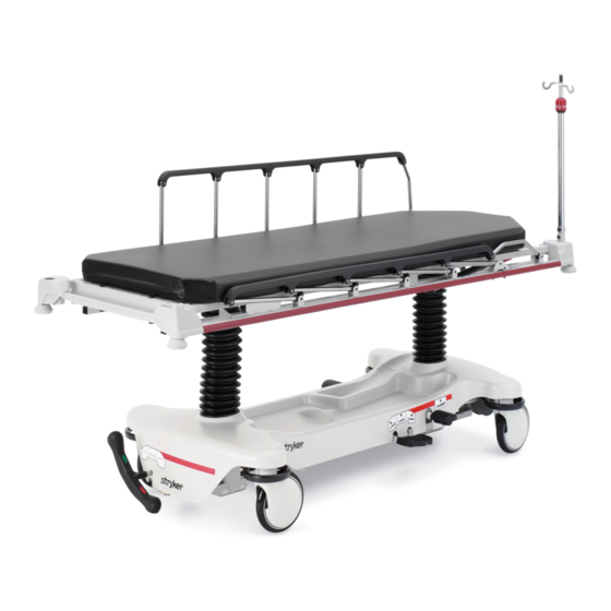
Introduction INTRODUCTION This manual is designed to assist you with the maintenance of the Model 736 Transport Stretcher. Read it thoroughly before using the equipment or beginning any maintenance on it. SPECIFICATIONS Maximum Weight Capacity 500 pounds Overall Stretcher Length \ Width 83”... -
Page 5: Summary Of Safety Precautions
Summary of Safety Precautions Before operating this stretcher, it is important to read and understand all information in this manual. Carefully read and strictly follow the warnings and cautions listed on this page. WARNING Always apply the caster brakes when a patient is getting on or off the stretcher. Push on the stretcher to en- sure the brakes are securely locked. -
Page 6: Preventative Maintenance
Preventative maintenance should be performed at a minimum of annually. A preventative maintenance pro- gram should be established for all Stryker Medical equipment. Preventative maintenance may need to be performed more frequently based on the usage level of the product. -
Page 7: Cleaning
If these types of products are used to clean Stryker patient handling equipment, measures must be taken to insure the stretchers are rinsed with clean water and thoroughly dried following cleaning. Failure to properly rinse and dry the stretchers will leave a cor- rosive residue on the surface of the stretcher, possibly causing premature corrosion of critical components. -
Page 8: Service Information
Service Information CASTER COVER INSTALLATION AND REMOVAL Double Prongs Looking through the larger of the two side cut−outs, align the cover with the axle nut or bolt head, as shown. Single Prong Push down on the opposite side of the cover until the single prong engages the caster horn. -
Page 9: Brake Rod Removal
Service Information BRAKE ROD REMOVAL Required Tools: Hammer 7/32” Punch String or Bungee Cords 1. Pump the litter up to full height. 2. Lift the base hood and support it from the litter using string or bungee cords. 3. Remove the hex head cap screws connecting the brake rod supports to the base frame. 4. -
Page 10: Release Pedal Adjustment
Service Information RELEASE PEDAL ADJUSTMENT 1. Manually disengage the release pedal swivel (item J on page 31) from the release pedal assembly. 2. To increase the release rod engagement with the release valve, turn the release pedal swivel clockwise on the threaded release rod. 3. -
Page 11: Brake Ring Removal
Service Information BRAKE RING REMOVAL Required Tools: 9/16” Socket w/Extension 3/8” Drive Ratchet Needle−Nose Pliers String or Bungee Cord 1. Pump the litter up to full height. 2. Lift the base hood and support it from the litter using string or bungee cords. 3. -
Page 12: Litter Top Removal
Service Information LITTER TOP REMOVAL Required Tools: 1/2” Socket w/Extension 3/8” Drive Ratchet Standard Screwdriver 1. Using the foot pedal, pump up the litter top to full height. 2. Remove the stretcher mattress 3. Remove the round, black hole plugs from the jack supports at each end of the litter to expose the jack support tube truss head screws. -
Page 13: Head End Hydraulic Jack Removal
Service Information HEAD END HYDRAULIC JACK REMOVAL Required Tools: 1/2” Socket w/Extension 3/8” Drive Ratchet 1. Remove the litter top from the stretcher (see page 11). 2. Using a 1/2” socket with extension and a 3/8” drive ratchet, remove the two hex head screws holding the jack base to the stretcher base frame. -
Page 14: Pneumatic Fowler Adjustment
Service Information PNEUMATIC FOWLER ADJUSTMENT Required Tools: 5/32” Hex Allen Wrench 1/2” Open End Wrench 1. Refer to the pneumatic Fowler assembly drawing on page 50 for parts reference. 2. For easier access, raise the Fowler to 75_ or higher. 3. -
Page 15: Quick Reference Replacement Parts List
The parts and accessories listed on this page are all currently available for purchase. Some of the parts identi- fied on the assembly drawings pages in this manual may not be individually available for purchase. Please call Stryker Customer Service at 1−800−327−0770 for availability and pricing. Return to Table of Contents... -
Page 16: Assembly Drawings And Parts Lists Fifth Wheel Base Assembly
0853−006−110 Retractable 5th Wheel Base Assembly Item Part No. Part Name Qty. 0023−288−000 Hex Washer Hd. Screw 0023−305−000 Hex Hd. Cap Screw 0753−006−148 Cam Bearing (page Fifth Wheel Assembly Return to Table of Contents... - Page 17 0853−006−130 Fifth Wheel Assembly Return to Table of Contents...
- Page 18 0853−006−130 Fifth Wheel Assembly Item Part No. Part Name Qty. 0003−083−000 Hex Hd. Cap Screw 0011−360−000 Washer 0016−035−000 Nylock Hex Nut 0023−288−000 Hex Washer Hd. Screw 0025−050−000 Rivet 0029−007−000 Dual Lock 0029−009−000 Dual Lock 0753−006−074 Torsion Spring 0753−006−075 Torsion Spring 0753−006−097 Drive Shaft Bearing 0753−006−106...
-
Page 19: Standard Brake Assembly (Fifth Wheel Base)
Standard Brake Assembly (Fifth Wheel Base) Assembly part number 0853−003−205 (reference only) Return to Table of Contents... - Page 20 Standard Brake Assembly (Fifth Wheel Base) Typical Both Ends Typical Assembly Both Ends Item Part No. Part Name Qty. 0003−364−000 Hex Screw 0005−044−000 Step Bolt 0011−262−000 Washer 0013−018−000 Tooth Lock Washer 0016−035−000 Nylock Hex Nut 0016−049−000 Nylock Hex Nut 0023−288−000 Hex Washer Hd.
-
Page 21: Brake Rod Assembly
Brake Rod Assembly Assembly part number 0853−003−201 (reference only) Item Part No. Part Name Qty. 0026−014−000 Slotted Spring Pin 0026−273−000 Clevis Pin 0027−020−000 Rue Ring Cotter 0753−003−015 Brake Rod Nyliner 0853−003−004 Brake Rod Support (page Drive Link Assembly 0853−003−014 Brake Rod (page Drive Link Assembly 1210−201−335... - Page 22 0853−003−010 Drive Link Assembly Item Part No. Part Name Qty. 0753−003−098 Flat Hd. Semi−Tubular Rivet 0753−203−102 Brake Cam 0853−003−011 Brake Rod Drive Link 0853−003−061 Brake Cam Drive Link Return to Table of Contents...
- Page 23 0853−006−135 Drive Link Assembly Item Part No. Part Name Qty. 0753−003−098 Semi−Tubular Rivet 0853−003−011 Brake Rod Drive Link 0853−006−022 5th Wheel Cam Drive Link 0853−006−047 5th Wheel Cam Drive Link Return to Table of Contents...
-
Page 24: Caster Assembly
0753−010−220 8” Caster Assembly Item Part No. Part Name Qty. 0003−099−000 Hex Hd. Cap Screw 0016−060−000 Centerlock Nut 0753−003−215 Wheel 0753−010−021 Caster Horn w/Bearing Return to Table of Contents... -
Page 25: Side Control Brake Assembly
Side Control Brake Assembly Assembly part number 0853−003−220 (reference only) Return to Table of Contents... - Page 26 Side Control Brake Assembly See Detail A Detail A Typical Both Ends Return to Table of Contents...
- Page 27 Side Control Brake Assembly Typical Assembly Both Ends Item Part No. Part Name Qty. 0003−364−000 Slotted Screw 0005−044−000 Step Bolt 0011−262−000 Washer 0013−018−000 Tooth Lock Washer 0016−035−000 Nylock Hex Nut 0016−049−000 Nylock Hex Nut 0023−233−000 Hex Washer Head Screw 0026−340−000 Clevis Pin 0027−012−000 Hitch Pin...
-
Page 28: Brake Rod / Side Control Assembly
Brake Rod / Side Control Assembly Assembly part number 0853−003−225 (reference only) Item Part No. Part Name Qty. 0026−014−000 Slotted Spring Pin 0026−273−000 Clevis Pin 0027−020−000 Rue Ring Cotter 0753−003−015 Brake Rod Nyliner 0753−003−112 Side Control Link 0753−003−004 Brake Rod Support (page Drive Link Assembly 0853−003−014... -
Page 29: Side Control Brake Sub−Assembly
Side Control Brake Sub−Assembly Assembly part number 0853−003−210 (reference only) Item Part No. Part Name Qty. 0026−014−000 Slotted Spring Pin 0026−340−000 Clevis Pin 0027−020−000 Rue Ring Cotter 0753−003−112 Side Control Link 0753−003−117 Rod End Link 0853−003−214 Side Control Shaft Support 0853−003−319 Side Control Brake Rod 1210−201−335... -
Page 30: Side Control Brake Assembly, Colored Components
Standard Brake Assembly, Colored Components Assembly Part Number 0853−003−620 (reference only) Part Number Part Description Quantity 0753−003−128 Brake Ring Weldment (Black) 0753−010−020 8” Caster Assembly (Black) 0753−201−126 Pump Pedal (Black) 0853−005−154 Butterfly “V” Pedal (Black) 1061−201−127 Short Uni−Pedal (Black) Side Control Brake Assembly, Colored Components Assembly Part Number 0853−003−630 (reference only) Part Number Part Description... -
Page 31: Dual Sided Hydraulics Assembly (Fifth Wheel Base)
Dual Sided Hydraulics Assembly (Fifth Wheel Base) Assembly part number 0853−005−525 Return to Table of Contents... - Page 32 Dual Sided Hydraulics Assembly (Fifth Wheel Base) See Detail A Detail A Return to Table of Contents...
- Page 33 Dual Sided Hydraulics Assembly (Fifth Wheel Base) Insert Head End Release Rod into Release Valve Assembly as shown Insert Foot End Release Rod into Release Valve Assembly as shown Item Part No. Part Name Qty. 0011−023−000 Washer 0014−071−000 Washer 0023−288−000 Hex Washer Hd.
-
Page 34: End Control Hydraulics Assembly, Colored Components
Standard Hydraulics Assembly, Colored Components Assembly Part Number 0853−005−650 (reference only) Part Number Part Description Quantity 0753−201−126 Pump Pedal (Black) 0853−005−154 Butterfly “V” Pedal (Black) 1061−201−127 Short Uni−Pedal (Black) End Control Hydraulics Assembly, Colored Components Assembly Part Number 0853−005−660 (reference only) Part Number Part Description Quantity... -
Page 35: Lowering Pedal Assembly
0853−004−251 Lowering Pedal Assembly Item Part No. Part Name Qty. 0025−133−000 Rivet 0753−004−029 Release Pedal Standoff 0853−004−004 Release Pedal Weldment 0853−004−320 Release Pedal Support 1069−004−320 Release Pedal Support Return to Table of Contents... -
Page 36: Head End Pump Pedal Assembly
0853−005−285 Head End Pump Pedal Assembly Item Part No. Part Name Qty. 0026−343−000 Groove Pin 0715−001−140 Vinyl Tube 0853−005−180 Head End Pump Pedal Weldment Return to Table of Contents... -
Page 37: Non−Constant Descent Jack
Non−Constant Descent Jack Assembly part number 0853−002−180 (reference only) Item Part No. Part Name Qty. 0023−288−000 Hex Washer Hd. Screw (page Jack Assembly, Non−Constant Descent 0853−010−007 Reservoir Clamp Return to Table of Contents... -
Page 38: Non−Constant Jack Assembly
0753−002−170 Non−Constant Jack Assembly Item Part No. Part Name Qty. 0045−273−000 O−Ring 0045−274−000 O−Ring 0048−190−000 U−Cup Seal 0753−002−017 Jack Cap (page Jack Base Assembly, Non−Constant Descent 0753−002−104 Actuator Rod Assembly 0753−002−106 Actuator Cylinder Assembly 0753−102−129 Reservoir Tube 0753−202−115 Jack Assembly Label Return to Table of Contents... -
Page 39: Jack Base Assembly, Variable Descent Jacks
Jack Base Assembly, Variable Descent Jack Assembly part number 0753−002−075 (reference only) Item Part No. Part Name Qty. 0046−004−000 O−Ring 0048−021−000 CV Plug 0390−002−134 Conical Compression Spring 0715−001−341 Poppet 0753−002−003 Pump Ram Assembly 0753−002−010 Jack Base 0753−002−019 Valve Filter 0753−002−051 Plug Assembly 0753−002−052 Check Valve Assembly... - Page 40 Notes Return to Table of Contents...
-
Page 41: Base Labeling Assembly, Standard Brakes
Base Labeling Assembly, Standard Brakes Assembly part number 0853−010−062 (reference only) Department Label page 42 Specification Label (Serial Number Location) FOOT END HEAD END Item Part No. Part Name Qty. 0853−001−040 Base Hood 1040−010−134 Bellows 0946−201−060 Stryker Logo Label Return to Table of Contents... -
Page 42: Base Labeling Assembly, 4−Sided Brakes
Department Label page 42 Specification Label (Serial Number Location) FOOT END HEAD END Item Part No. Part Name Qty. 0853−001−041 Base Hood 1040−010−134 Bellows 0946−201−060 Stryker Logo Label 0853−010−018 Brake/Steer Label, Right 0853−010−019 Brake/Steer Label, Left Return to Table of Contents... -
Page 43: Base Labeling Assembly, Colored Components
Base Labeling, Colored Components Assembly Part Number 0853−010−062 (reference only) Item D Item E Item F Item G Label Color P/N Brake/Steer, Lift/Lower, Left Brake/Steer, Lift/Lower, Right Color Foot End Head End 0853−010−120 0753−010−051 0853−010−055 0753−010−017 0853−010−054 PURPLE 0853−010−121 0753−010−151 0853−010−155 0753−010−170 0853−010−154... -
Page 44: Litter Assembly
Litter Assembly Assembly part number 0736−010−010 (reference only) Return to Table of Contents... - Page 45 Litter Assembly Return to Table of Contents...
- Page 46 Litter Assembly Return to Table of Contents...
- Page 47 Litter Assembly Item Part No. Part Name Qty. 0002−031−000 0003−047−000 Hex Hd. Cap Screw 0003−078−000 Hex Hd. Cap Screw 0004−135−000 Button Hd. Cap Screw 0004−201−000 0004−515−000 Button Hd. Cap Screw 0007−074−000 Truss Hd. Machine Screw 0011−002−000 Washer 0011−360−000 Washer 0014−003−000 Washer 0014−021−000 Washer...
- Page 48 Litter Assembly Item Part No. Part Name Qty. 1510−234−027 Mid−Section Skin 1510−234−028 Thigh Section Skin 1510−234−126 Calf Section Skin 1550−030−005 Frame Weldment 1550−034−021 Thigh Support 0785−034−005 Velcro Pile 1550−090−034 Engage Gatch Label 1210−800−008 Patent Label Return to Table of Contents...
-
Page 49: Knee Gatch Crankscrew Assembly
0736−046−010 Knee Gatch Crankscrew Assembly Item Part No. Part Name Qty. 0004−007−000 Slot Head Cap Screw 0016−005−000 0026−010−000 Slotted Spring Pin 0026−014−000 Slotted Spring Pin 0026−045−000 Slotted Spring Pin 0081−174−000 Washer 0081−175−000 Washer 0081−176−000 Washer 0378−024−029 Slot Head Shoulder Bolt 0938−001−175 Bearing Assembly 0938−001−177... -
Page 50: Siderail Assembly
1010−026−017 Siderail Assembly, Right 1010−026−019 Siderail Assembly, Left (Left Side Shown) Item Part No. Part Name Qty. 1010−026−015 Top Rail 1010−026−083 Upright 1010−026−084 Upright, Bent 1010−026−082 Spacer 0025−106−000 Semi−Tubular Rivet 1010−026−010 Round Hole Plug 1010−026−085 Upright, Latch 1010−026−012 Bent Spindle Stop Return to Table of Contents... -
Page 51: Pneumatic Fowler Assembly
0736−031−120 Pneumatic Fowler Assembly Item Part No. Part Name Qty. 0004−161−000 Button Hd. Cap Screw 0007−020−000 Truss Hd. Machine Screw 0015−037−000 Hex Jam Nut 0015−050−000 Hex Nut 0016−028−000 Fiberlock Hex Nut 0021−125−000 Set Screw 0021−126−000 Set Screw 0025−120−000 Pop Rivot 1001−001−000 Hole Plug (page... -
Page 52: Fowler To Litter Assembly
0736−031−010 Fowler to Litter Assembly Item Part No. Part Name Qty. 0004−182−000 Button Hd. Cap Screw 0004−183−000 Button Hd. Cap Screw 0014−020−000 Washer 0014−021−000 Washer 0015−060−000 Nylock Hex Nut 0016−036−000 Nylock Hex Nut 0016−117−000 Stover Hex Lock Nut 0023−256−000 PanHead Sheet Metal Screw 0025−050−000 Rivot 0721−031−065... -
Page 53: Pneumatic Fowler Outer Housing Assembly
Pneumatic Fowler Outer Housing Assembly Assembly part number 1210−031−106 (Right) Item Part No. Part Name Qty. 0025−144−000 Semi−Tubular Rivet 1210−031−103 Pivot Tab 1210−031−104 Outer Housing, Right Assembly part number 1210−031−107 (Left) Item Part No. Part Name Qty. 0025−144−000 Semi−Tubular Rivet 1210−031−103 Pivot Tab 1210−031−105... -
Page 54: Removable I.v. Pole Assembly
0390−025−010 Standard, Removable I.V. Pole Assembly Item Part No. Part Name Qty. 0024−023−000 Plastic Knob 0390−003−053 Double IV Ass’y 0393−003−043 Tube Assembly 0004−496−000 Soc. Hd. Cap Screw Return to Table of Contents... -
Page 55: Corner Cover Assembly
Corner Cover Assembly Assembly part number (reference only) 0736−035−010 Head End 0736−035−060 Foot End FOOT END SHOWN Item Part No. Part Name 0023−104−000 Pan Head Screw 0037−059−000 Hole Plug 1010−201−238 Corner Cover/Slot 1010−201−239 Corner Cover/Hole Return to Table of Contents... -
Page 56: Corner Cover, Push Handle Assembly
Corner Cover, Push Handle Assembly Assembly part number (reference only) 0736−035−015 Head End 0736−035−065 Foot End HEAD END SHOWN Item Part No. Part Name 0023−104−000 0037−059−000 Hole Plug 1010−201−236 Corner Cover Hole/Slot 1010−201−237 Corner Cover Hole/Hole 0003−047−000 Hex Head Cap Screw 0003−050−000 Hex Head Cap Screw 0016−028−000... -
Page 57: Corner Cover, 2−Stage I.v. Assembly
Corner Cover, 2−Stage I.V. Assembly Assembly part number (reference only) 0736−035−020 Head End 0736−035−070 Foot End HEAD END SHOWN Item Part No. Part Name 0023−104−000 Pan Head Screw 1010−201−238 Corner Cover Slot 1010−201−239 Corner Cover Hole 0003−050−000 Hex Head Cap Screw 0016−028−000 Fiberlock Hex Nut 0004−199−000... -
Page 58: Corner Cover, 2−Stage I.v., Push Handle Assembly
Corner Cover, 2−Stage I.V., Push Handle Assembly Assembly part number (reference only) 0736−035−025 Head End 0736−035−075 Foot End HEAD END SHOWN Item Part No. Part Name 0023−104−000 Pan Head Screw 1010−201−238 Corner Cover Slot 1010−201−239 Corner Cover Hole 0003−047−000 Hex Head Cap Screw 0003−050−000 Hex Head Cap Screw 0016−028−000... -
Page 59: Corner Cover, 3−Stage I.v. Assembly
Corner Cover, 3−Stage I.V. Assembly Assembly part number (reference only) 0736−035−030 Head End 0736−035−080 Foot End HEAD END SHOWN Item Part No. Part Name 0023−104−000 Pan Head Screw 1010−201−238 Corner Cover Slot 1010−201−239 Corner Cover Hole 0003−050−000 Hex Head Cap Screw 0016−028−000 Fiberlock Hex Nut 0004−199−000... -
Page 60: Corner Cover, 3−Stage I.v., Push Handle Assembly
Corner Cover, 3−Stage I.V., Push Handle Assembly Assembly part number (reference only) 0736−035−035 Head End 0736−035−085 Foot End HEAD END SHOWN Item Part No. Part Name 0023−104−000 Pan Head Screw 1010−201−238 Corner Cover Slot 1010−201−239 Corner Cover Hole 0003−047−000 Hex Head Cap Screw 0003−050−000 Hex Head Cap Screw 0016−028−000... -
Page 61: Push Handle Assembly
1211−351−010 Push Handle Assembly Item Part No. Part Name Qty. 1010−354−024 Stop Link 1211−151−018 Sleeve Assembly 0026−118−000 Roll Pin Return to Table of Contents... -
Page 62: Optional 2−Stage I.v. Pole Assembly
1211−210−010 Optional 2−Stage I.V. Pole Assemby Item Part No. Part Name Qty. 0008−031−000 Soc. Hd. Cap Screw 0052−017−000 Washer 0926−400−162 Spacer 1211−210−029 2nd Stage Assembly 1001−359−013 Dampener 1001−159−028 Base Tube 1010−059−016 I.V. Hook (page I.V. Pole Latch 1001−359−112 Pivot Return to Table of Contents... -
Page 63: Optional 3−Stage I.v. Pole Assembly
1211−211−010 Optional 3−Stage I.V. Pole Assembly Item Part No. Part Name Qty. 0007−004−000 Truss Hd. Machine Screw 0026−076−000 Roll Pin 0052−017−000 Spacer 0926−400−162 Spacer (page 3rd Stage Assembly 1001−161−023 Base Tube 1010−059−016 I.V. Hook 1010−061−014 Collar (page I.V. Pole Latch 1001−359−013 Dampener 1001−359−014... -
Page 64: 3−Stage I.v. 3Rd Stage Assembly
3−Stage I.V. Pole 3rd Stage Assembly Assembly part number 1211−110−032 (reference only) NOTE Item F, part number 1010−061−018 is left hand thread. When removing it, turn clockwise to loosen it. Item Part No. Part Name Qty. 0031−021−000 Ball 0038−303−000 Compression Spring 1010−061−013 Ball Retainer 1010−061−016... -
Page 65: Pole Latch
1211−210−026 I.V. Pole Latch Assembly Item Part No. Part Name Qty. 0028−167−000 Retaining Ring 0031−004−000 Steel Ball 0038−392−000 Crest−to−Crest Spring 1211−091−034 Release Label 1211−110−018 I.V. Latch Seal 1211−110−020 Washer 1211−110−021 I.V. Latch Locking Pin 1211−110−022 I.V. Latch Guide 1211−110−024 I.V. Latch O.D. Housing 1211−110−035 Washer 1211−110−036... -
Page 66: Defibrillator Tray Assembly
0785−045−200 Optional Defibrillator Tray Assembly Item Part No. Part Name Qty. Item Part No. Part Name Qty. 0002−044−000 Machine Screw 0785−045−703 Weight Capacity Label 0025−055−000 Blind Hole Rivot 0785−045−204 Tray Support 0029−008−000 Dual Lock 0785−045−207 Tray 0029−010−000 Dual Lock 0785−045−208 Bayonet 0785−045−201 Defib Tray Label... -
Page 67: Foot Extension/Defibrillator Tray Assembly
0785−045−400 Foot Extension/Defibrillator Tray Ass’y Item Part No. Part Name Qty. Item Part No. Part Name Qty. 0004−215−000 Button Head Cap Screw 0785−045−401 Foot Ext/Defib Tray Label 1 0008−049−000 Shoulder Bolt 0785−045−405 Cushion 0014−020−000 Washer 0785−045−410 Base MTG. Wldmt. 0014−120−000 Washer 0785−045−420 Frame−Pivot Wldmt. -
Page 68: Foot Board/Chartholder Assembly
0785−045−500 Foot Board/Chartholder Assembly Item Part No. Part Name Qty. 0785−045−402 Push/Pull Label 0785−045−501 Foot Board Label 0785−45−511 Chart Holder Thermoform 0785−045−512 Foot Board, Back 0785−045−513 Foot Board, Front 0785−045−514 Standoff, Small 0785−045−515 Standoff, Large 0946−029−010 Support Return to Table of Contents... -
Page 69: Upright O 2 Bottle Holder Assembly
1020−130−000 Upright O Bottle Holder Assembly Item Part No. Part Name Qty. 0027−030−000 Hair Pin Cotter 1020−030−111 Upright Bottle Holder 1020−030−017 Specification Label 1040−010−090 Optional O Bottle Retainer Assembly Base Hood Item Part No. Part Name Qty. 1040−010−091 Bottle Retainer 1040−010−092 Scrulok Fastener Return to Table of Contents... -
Page 70: Mattresses And Siderail Pads
Mattresses and Siderail Pads Mattress, 4” Thick x 30” Wide, Enhanced Comfort ....part # 0785−034−323 Mattress, 4” Thick x 30” Wide, Ultra Comfort . -
Page 71: Warranty
Stryker’s obligation under this warranty is expressly limited to supplying replacement parts and labor for, or replacing, at its option, any product which is, in the sole discretion of Stryker, found to be defective. If re- quested by Stryker, products or parts for which a warranty claim is made shall be returned prepaid to Stryker’s factory. -
Page 72: Return Authorization
Stryker will perform all service during regular business hours (9−5) * Replacement parts and labor for products under PM contract will be discounted. ** Does not include any disposable items, I.V. poles (except for Stryker HD permanent poles), mattresses, or damage re- sulting from abuse. - Page 73 European Representative Stryker EMEA RA/QA Director Stryker France ZAC Satolas Green Pusignan Av. De Satolas Green 69881 MEYZIEU Cedex France 3800 E. Centre Ave., Portage, MI 49002 (800) 327−0770 www.stryker.com JH 02/07 0736−109−002 REV A...
Need help?
Do you have a question about the 736 and is the answer not in the manual?
Questions and answers