Table of Contents
Advertisement
Quick Links
Advertisement
Table of Contents

Subscribe to Our Youtube Channel
Related Manuals for SKF EPUMP


Summary of Contents for SKF EPUMP
- Page 1 Assembly Instructions Electrical Barrel Pumping Unit- EPUMP (Original operating and maintenance instructions according to EU Directive 2006/42/EC) Date: 23.5.2022 Document no.: EPUMP Version: 2A Read this manual before installing or commissioning the product and keep it at hand for later reference!
- Page 2 The special technical documents were prepared following Annex VII part B. Upon justifiable request, these special technical documents can be forwarded electronically to the respective national authorities. The authorized company for the compilation of the technical documentation is SKF (U.K.) Limited, 2 Canada Close, Banbury, Oxfordshire, OX16 2RT, GBR. Designation:...
- Page 3 Description of the essential health and safety requirements according to 2006/42/EC, Annex I, which have been applied and fulfilled. Any essential health and safety requirements not listed here are not relevant to this product Table 1 Appendix to Declaration of Incorporation Valid for: EPUMP lubricant feed pumps No.: Essential health and safety requirement Applicable: Fulfilled: 1.1.2...
-
Page 4: Masthead
The instructions contain no statements regarding the warranty or liability for defects. That information can be found in our General Terms of Payment and Delivery. Training We conduct detailed training in order to enable maximum safety and efficiency. We recommend taking advantage of this training. For further information, contact your authorized SKF dealer or the manufacturer. -
Page 5: Table Of Contents
Table of contents Masthead ............................................4 Table of contents ......................................... 5 Safety alerts, visual presentation, and layout................................ 7 1. Safety instructions ........................................8 General safety instructions ....................................8 General electrical safety instructions .................................. 8 General behaviour when handling the product ..............................8 Intended use.......................................... - Page 6 5. Operation ..........................................61 Start-up EPUMP-ECO ......................................61 Start-up EPUMP-STA ......................................63 Replacing the lubricant barrel EPUMP-ECO..............................65 Replacing the lubricant barrel EPUMP-STA ..............................66 6. Regular inspections ........................................66 7. Troubleshooting ........................................67 8. Technical specification ......................................68 Technical data ........................................68 Connections ........................................
-
Page 7: Safety Alerts, Visual Presentation, And Layout
Safety alerts, visual presentation, and layout While reading these instructions, you will encounter various symbols, illustrations, and text layouts intended to help you navigate and understand the instructions. Their meaning is explained below. Safety alerts: Activities that present specific hazards (to life and limb or possible damage to property) are indicated by safety alerts. Always be sure to follow the instructions given in the safety alerts. -
Page 8: Safety Instructions
• Unauthorized modifications and changes can have an unpredictable effect on safety and operation. Unauthorized modifications and changes are therefore prohibited. Only original SKF spare parts and SKF accessories may be used. • Any unclear points regarding proper condition or correct assembly/operation must be clarified. Operation is prohibited until issues have been clarified. -
Page 9: Persons Authorized To Use The Product
Persons authorized to use the product Operator A person who is qualified by training, knowledge and experience to carry out the functions and activities related to normal operation. This includes avoiding possible hazards that may arise during operation. Specialist in mechanics Person with appropriate professional education, knowledge and experience to detect and avoid the hazards that may arise during transport, installation, start-up, operation, maintenance, repair and disassembly. -
Page 10: Note On Pressure Equipment Directive
Type identification plate Note on Pressure Equipment Directive Due to its performance characteristics, the product does not reach the limit values defined in Article 4, Paragraph 1, Subparagraph (a) (ii) and is excluded from the scope of Pressure Equipment Directive 2014/68/EU in accordance with Article 1, Paragraph 2 Subparagraph (f). -
Page 11: Note On China Rohs Mark
Note on China RoHS mark The China RoHS marking confirms that there is no danger to persons or the environment from the regulated substances contained within the intended period of use (number in the circle) of the product. Emergency shutdown This is done by a course of action to be defined by the operator. -
Page 12: Residual Risks
Residual risks Table 2 Residual risks Residual risk Possible in life cycle Prevention/ remedy Personal injury/ material damage A B C G H K Keep unauthorized persons away. No people may due to falling of raised parts remain under suspended loads. Lift parts with adequate lifting devices. -
Page 13: Lubricants
• The lubricant’s ignition temperature has to be at least 50 Celsius above the maximum surface temperature of the components. Solid lubricants Solid lubricants may only be used after prior consultation with SKF. When solid lubricants are used in lubrication systems, the following rules generally apply: Graphite: •... -
Page 14: General Description
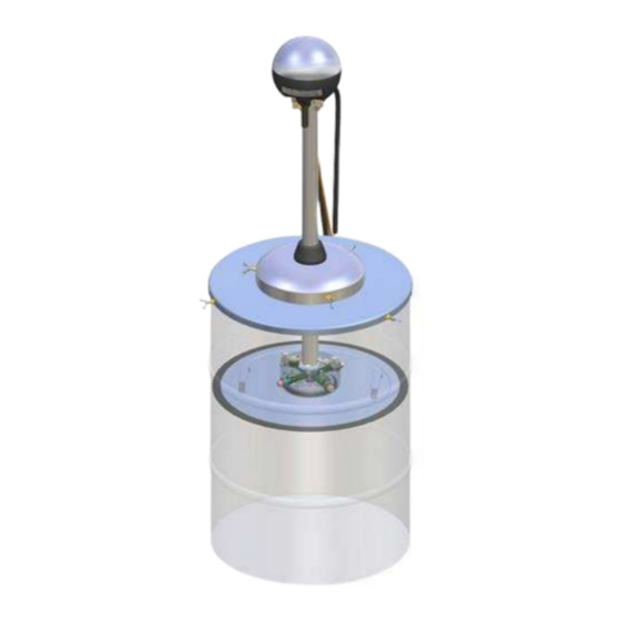
The pumping unit is connected to a follower plate placed inside the lubricant barrel. This allows the pumping unit to follow the lubricant level. NOTE The SKF-EPUMP-XXX-ECO is intended for use with ECO lid sets, which are suitable for greases in NLGI grades 1 and 2. NOTE... -
Page 15: Design
Design SKF Electrical barrel pumping unit, complete pumping center Figure 1 Item Description Pumping unit Lid set Power supply unit / external control center Hoses Line valve 6, 7 Shut-off valve (optional) -
Page 16: Electrical Barrel Pumping Unit-Eco
3.1.1 ELECTRICAL BARREL PUMPING UNIT-ECO Figure 2 EPUMP-XXX-ECO pumping unit, design Item Description Pressure relief valve Pumping element (4 pcs) Heating element Low level switch Operation button M12-connector (in models P & 1) Electric motor Circuit board Pressure sensor Check valve... - Page 17 Figure 3 EPUMP-XXX-ECO lid set Item Description Bracket for pumping unit/line valve Hook for lifting the follower plate Follower plate Barrel lid Hose assembly Grease filter NOTE * 6 Grease filter is delivered with the line valve assembly. Refer to manual, Line valve...
-
Page 18: Electrical Barrel Pumping Unit- Sta
3.1.2 ELECTRICAL BARREL PUMPING UNIT- STA Figure 4 EPUMP-XXX-STA pumping unit, design Item Description Pressure relief valve Pumping element (4 pcs) Low level switch M12-connector (in models P & 1) Operation button Electric motor Circuit board Pressure sensor Check valve... - Page 19 Figure 5 EPUMP-XXX-STA lid set Item Description Bracket for pumping unit/line valve Barrel lid Hose assembly Grease filter NOTE * 4 Grease filter is delivered with the line valve assembly. Refer to manual, Line valve E-VALV (OEVLXXXX.pdf).
-
Page 20: Control
Control configuration and operation instructions, single-line system, internal control These instructions apply to single-line, single-channel lubrication systems with internal control. Type code of the pumping unit: EPUMP-XX-XXX-24-1. All single-line, multi-channel lubrication systems require an external SKF control center. LED-display M12-connection for valve Operation button... -
Page 21: Technical Specifications
4.1.1 Technical specifications Operating voltage 24VDC (20-32 VDC) Power consumption 5A max when the pumping is on 0.1A max when the pumping unit is switched on, pumping is off and heating is off. 2A max when pumping is off and heating is on. Peak current 12A, 100 ms max when pumping starts. -
Page 22: Connections
4.1.2 Connections The pumping unit is delivered with a 3 m, 6-pole cable that has a detachable connector. The cable is connected to the main connector X1 on the circuit board EP-Co. Wire color Signal Pin of X1 on circuit 6-pole cable board Black... - Page 23 Connector X1 Connector X7 Configuration button Figure 7 Circuit board, EP-Co...
-
Page 24: Operation Modes
The mode is set in factory according to the application. The operation mode can be changed. Yellow LEDs display the selected mode for 2 seconds, when the pumping unit is switched on. Table 3 Operation mode display at power up LED display Selected operation mode 1: SKF-EPUMP-XX-XXX-24-CC 2: SKF-EPUMP-XX-XXX-24-CC 3: SKF-EPUMP-XX-XXX-24-LU 4: SKF-EPUMP-XX-XXX-24-P 5: SKF-EPUMP-XX-XXX-24-1 6: SKF-EPUMP-XX-XXX-24-1... - Page 25 Operation modes 5 - 7: Lubrication system implemented with single-line dosers General The pumping unit operates as an independent lubrication unit in a system which is implemented with single-line dosers. The pressure is controlled by an external pressure switch and an external line valve. Operation modes 5 - 7 differ in operation when pressurized.
-
Page 26: Setting The Parameters
Table 5 Lubrication parameters, when table R is selected Settings display Lubrication cycle [min] Maximum pressurization time [min] 1440 4.1.4 Setting the parameters Setting the lubrication cycle Press the operation button until the green LED starts to blink (5 s). Select the new value by pressing the operation button. Exit the settings mode by pressing the operation button until the green LED stops blinking (5 s). -
Page 27: Lubrication Operation
4.1.5 Lubrication operation Interval counting The pumping unit pressurizes at intervals that are set using the parameter lubrication cycle. When the interval is counted, the green LED is lit and the yellow LEDs show the elapsed interval time. For example, if the lubrication cycle is set to 60 min and 30 min (50%) of the interval have elapsed, the display is as below: When the interval is completed, the pumping unit starts pressurizing. -
Page 28: Alarms
4.1.6 Alarms The relay output is open in alarm mode in operation modes 5 - 7. Pressure alarm A pressure alarm is triggered in the following conditions: " The pressure switch is closed when pressurization starts. " The pressure switch does not close within the set maximum pressurization time. The red alarm LED blinks and the alarm output is activated. -
Page 29: Pressure Control
4.1.7 Pressure control General When the pressurization is in progress, the output pressure is controlled by an integrated pressure sensor and a set pressure limit. When the pressure rises above the set limit, pumping stops. Pumping is restarted when the pressure drops below the pressure limit minus the set hysteresis. - Page 30 Displaying and setting pressure limit Press the configuration button on the circuit board for about 5 seconds. Release the button when the green LED starts to blink fast. The set value is now displayed by pressure LEDs. A new value can be set by pressing the configuration button. Each time the button is pushed, the set value increases by one step (25 bar).
-
Page 31: Adjusting Run Time Of The Pumping Unit
4.1.8 Adjusting run time of the pumping unit < NOTICE Incorrect use of the lubrication system or improper settings and adjustments of the system may cause damage to the machine or equipment that is lubricated. General It is possible to drop the pump’s rotation speed per minute by setting the parameter Duty cycle to less than 100 %. The pump runs 1/4 of a revolution (0.4 s) and stops for a delay that depends on the set parameter. -
Page 32: Setting The Operation Configuration
Displaying and setting duty cycle Press the configuration button on the circuit board for about 15 seconds. Release the button when the green and red LEDs start to blink fast. The set value is now displayed by the yellow LEDs. Table 7 Duty cycle display LED display... - Page 33 The yellow LEDs show the selected operation mode. Change the mode by pressing the configuration button. Exit the settings mode by switching OFF the power. Table 8 Operation mode display LED display Selected operation mode 1: SKF-EPUMP-XX-XXX-24-CC 2: SKF-EPUMP-XX-XXX-24-CC 3: SKF-EPUMP-XX-XXX-24-LU 4: SKF-EPUMP-XX-XXX-24-P 5: SKF-EPUMP-XX-XXX-24-1 6: SKF-EPUMP-XX-XXX-24-1...
-
Page 34: Heating Control
The pumping unit is delivered with settings customized for the customer or the default factory settings. In the case of customized settings, these are detailed in a separate document delivered with the pumping unit. Table 9 Pumping unit, type SKF-EPUMP-XX-XXX-24-1, factory settings Setting Default value... -
Page 35: Control Configuration And Operation Instructions, External Control
Control configuration and operation instructions, external control These instructions apply to lubrication systems with external control. Type code of the pumping unit: EPUMP-XX-XXX-24-CC. All dual-line and multichannel lubrication systems require an external SKF control center. LED display Operation button Pressure... -
Page 36: Technical Specifications
4.2.1 Technical specifications Operating voltage 24VDC (20-32 VDC) Power consumption 5A max when the pumping is on 0.1A max when the pumping unit is switched on, pumping is off and heating is off. 2A max when pumping is off and heating is on. Peak current 12A, 100 ms max when pumping starts. -
Page 37: Connections
4.2.2 Connections The pumping unit is delivered with a 3 m, 6-pole cable that has a detachable connector. The cable is connected to the main connector X1 on the circuit board EP-Co. Connections in operation mode 1 Wire color Signal Pin of X1 on 6-pole cable circuit board... -
Page 38: Operation Modes
The mode is set in factory according to the application. The operation mode can be changed. Yellow LEDs display the selected mode for 2 seconds, when the pumping unit is switched on. Operation mode display at power up Table 10 LED display Selected operation mode 1: SKF-EPUMP-XX-XXX-24-CC 2: SKF-EPUMP-XX-XXX-24-CC 3: SKF-EPUMP-XX-XXX-24-LU 4: SKF-EPUMP-XX-XXX-24-P 5: SKF-EPUMP-XX-XXX-24-1 6: SKF-EPUMP-XX-XXX-24-1... -
Page 39: Operation Mode 2: Control With The Pumping Unit's Operating Voltage
Operation mode 1: Control with external signal General This operation mode is used when the pumping unit has been connected to the automatic lubrication system control. The pumping unit is controlled by an external control voltage (24 VDC / 10 mA). The operating voltage of the pumping unit is switched on separately. -
Page 40: Pressure Control
4.2.5 Pressure control General When the pressurization is in progress, the output pressure is controlled by an integrated pressure sensor and a set pressure limit. When the pressure rises above the set limit, pumping stops. Pumping is restarted when the pressure drops below the pressure limit minus the set hysteresis. - Page 41 Displaying and setting pressure limit Press the configuration button on the circuit board for about 5 seconds. Release the button when the green LED starts to blink fast. The set value is now displayed by the pressure LEDs. A new value can be set by pressing the configuration button. Each time the button is pushed, the set value increases by one step (25 bar).
-
Page 42: Adjusting Run Time Of The Pumping Unit
Output pressure display The output pressure is indicated as percentage values from the maximum pressure (250 bar) in basic operation modes 1- 3. The yellow LEDs show pressure values. Output pressure display [bar] <20 1…50 20…40 51…100 40…60 101…150 60…80 151…200 80…100 201…>250... - Page 43 < NOTICE Only the configuration button may be touched to avoid damage to other components on the circuit board. Displaying and setting duty cycle Press the configuration button on the circuit board for about 15 seconds. Release the button when the green and red LEDs start to blink fast.
-
Page 44: Setting The Operation Configuration
4.2.7 Setting the operation configuration < NOTICE Incorrect use of the lubrication system or improper settings and adjustments of the system may cause damage to the machine or equipment that is lubricated. The user can set the operation mode of the pumping unit and the lubrication parameter table. Exceptionally switch on the power of the pumping unit while the unit is open. -
Page 45: Heating Control
The pumping unit is delivered with settings customized for the customer or the default factory settings. In the case of customized settings, these are detailed in a separate document delivered with the pumping unit. Table 14 Pumping unit, type EPUMP-XX-XXX-24-CC, factory settings Setting Default value... -
Page 46: Control Configuration And Operation Instructions, Progressive System, Internal Control
4.3.1 General These instructions apply to progressive, single-channel lubrication systems with internal control. Type code of the pumping unit: EPUMP-XX-XXX-24-P. All progressive, multi-channel lubrication systems require an external SKF control center. LED display M12 connection to the Operation button... -
Page 47: Technical Specifications
4.3.2 Technical specifications Operating voltage 24VDC (20-32 VDC) Power consumption 5A max when the pumping is on 0.1A max when the pumping unit is switched on, pumping is off and heating is off. 2A max when pumping is off and heating is on. Peak current 12A, 100 ms max when pumping starts. -
Page 48: Connections
4.3.3 Connections The pumping unit is delivered with a 3 m, 6-pole cable that has a detachable connector. The cable is connected to the main connector X1 on the circuit board EP-Co. Wire color Signal Pin of X1 on circuit 6-pole cable board Black... - Page 49 Connector X1 Connector X7 Configuration button Figure 11 Circuit board, EP-Co...
-
Page 50: Operation Modes
Yellow LEDs display the selected mode for 2 seconds, when the pumping unit is switched on. Table 15 Operation mode display at power up LED display Selected operation mode 1: SKF-EPUMP-XX-XXX-24-CC 2: SKF-EPUMP-XX-XXX-24-CC 3: SKF-EPUMP-XX-XXX-24-LU 4: SKF-EPUMP-XX-XXX-24-P 5: SKF-EPUMP-XX-XXX-24-1... - Page 51 Operation mode 4: Lubrication system implemented with progressive feeders General The pumping unit operates as an independent lubrication unit in a system which is implemented with progressive feeders. The pumping unit has three settable parameters for the control: Lubrication cycle Maximum pressurization time Pulse count from the external pulse sensor The parameters can be selected from two parameter tables, G or R.
- Page 52 Table 17 Lubrication parameters, when table R is selected LED display Lubrication cycle Max pressurization time Pulse count [min] [min] 1440 Setting the parameters < NOTICE Incorrect use of the lubrication system or improper settings and adjustments of the system may cause damage to the machine or equipment that is lubricated.
- Page 53 Lubrication operation Interval counting The pumping unit pressurizes at intervals that are set using the parameter lubrication cycle. When the interval is counted, the green LED is lit and the yellow LEDs show the elapsed interval time. For example, if the lubrication cycle is set to 60 min and 30 min (50%) of the interval have elapsed, the display is shown as below: When the interval is completed, the pumping unit starts pressurizing.
-
Page 54: Pressure Control
4.3.5 Pressure control General When the pressurization is in progress, the output pressure is controlled by an integrated pressure sensor and a set pressure limit. When the pressure rises above the set limit, pumping stops. Pumping is restarted when the pressure drops below the pressure limit minus the set hysteresis. - Page 55 Displaying and setting pressure limit Press the configuration button on the circuit board for about 5 seconds. Release the button when the green LED starts to blink fast. The set value is now displayed by pressure LEDs. A new value can be set by pressing the configuration button. Each time the button is pushed, the set value increases by one step (25 bar).
-
Page 56: Adjusting Run Time Of The Pumping Unit
4.3.6 Adjusting run time of the pumping unit < NOTICE Incorrect use of the lubrication system or improper settings and adjustments of the system may cause damage to the machine or equipment that is lubricated. General It is possible to drop the pump’s rotation speed per minute by setting the parameter Duty cycle to less than 100 %. The pump runs 1/4 of a revolution (0.4 s) and stops for a delay that depends on the set parameter. - Page 57 Displaying and setting duty cycle Press the configuration button on the circuit board for about 15 seconds. Release the button when the green and red LEDs start to blink fast. The set value is now displayed by the yellow LEDs. Duty cycle display Table 19 LED display...
-
Page 58: Setting The Operation Configuration
4.3.7 Setting the operation configuration < NOTICE Incorrect use of the lubrication system or improper settings and adjustments of the system may cause damage to the machine or equipment that is lubricated. The user can set the operation mode of the pumping unit and the lubrication parameter table. Exceptionally switch on the power of the pumping unit while the unit is open. - Page 59 The yellow LEDs show the selected operation mode. Change the mode by pressing the configuration button. Exit the settings mode by switching the power OFF. Table 20 Operation mode display LED display Selected operation mode 1: SKF-EPUMP-XX-XXX-24-CC 2: SKF-EPUMP-XX-XXX-24-CC 3: SKF-EPUMP-XX-XXX-24-LU 4: SKF-EPUMP-XX-XXX-24-P 5: SKF-EPUMP-XX-XXX-24-1 6: SKF-EPUMP-XX-XXX-24-1...
-
Page 60: Heating Control
The pumping unit is delivered with settings customized for the customer or the default factory settings. In the case of customized settings, these are detailed in a separate document delivered with the pumping unit. Table 21 Pumping unit, type EPUMP-XX-XXX-24-P, factory settings Setting Default value... -
Page 61: Operation
If the lubricant level in the barrel drops to the low limit level during pumping, the low level switch sends an alarm to the control unit and pumping is stopped. The alarm can be disabled by replacing the lubricant barrel and resetting the alarm at the control unit. Start-up EPUMP-ECO < WARNING Electrical connections must only be made by qualified electricians. - Page 62 NOTE The numbers in brackets indicate position numbers in Figures 2 and 3. Check the condition of the lubricant barrel. Damage in the barrel will prevent the follower plate (3) from lowering. Remove the barrel’s original lid and press the follower plate closely on top of the lubricant in the barrel. Ensure that air is removed from below the follower plate and that the central unit of the follower plate is filled with lubricant.
-
Page 63: Start-Up Epump-Sta
Start-up EPUMP-STA < WARNING Electrical connections must only be made by qualified electricians. To minimize risk of electric shock or electrocution, ensure that the pumping center is turned off before making any connections. Operating voltage must be shut off before touching electrically conductive parts or opening any parts of the system or component. - Page 64 NOTE The numbers in brackets indicate position numbers in Figures 4 and 5. Check the condition of the lubricant barrel. Remove the barrel’s original lid. Barrel sizes 50 kg = 1/4 or 200 kg = 1/1 ³ Place the barrel lid’s extra edging (2) on the lubricant barrel. Fasten the extra edging with wing screws.
-
Page 65: Replacing The Lubricant Barrel Epump-Eco
Replacing the lubricant barrel EPUMP-ECO < WARNING Ensure that the system is not under pressure while you are replacing a lubricant barrel. Before opening the grease filter, remove pressure by opening the venting screw in the filter plug (³ Figure 6, (15)). If the system is under pressure when the components are being disconnected or opened, the components or lubricant might be flung in the air causing injury to people or damage to the environment. -
Page 66: Replacing The Lubricant Barrel Epump-Sta
Replacing the lubricant barrel EPUMP-STA < WARNING Ensure that the system is not under pressure while you are replacing a lubricant barrel. Before opening the grease filter, remove pressure by opening the venting screw in the filter plug (³ Figure 7, (15)). If the system is under pressure when the components are being disconnected or opened, the components or lubricant might be flung in the air causing injury to people or damage to the environment. -
Page 67: Troubleshooting
7. Troubleshooting < WARNING Before solving the following operation disturbances, turn off the power at the control and pumping center. Before opening the grease filter, remove pressure from the system by opening the venting screw in the filter plug.( ³ Figures 12/13, (15)). If the system is under pressure when the components are being disconnected or opened, the components or lubricant might be flung in the air causing injury to people or damage to the environment. -
Page 68: Technical Specification
8. Technical specification Technical data Value Unit Description -30…+70 °C Operating temperature range -20…+160 °F Maximum pressure 4300 (ensured with a pressure relief valve) 24 VDC (20…32 VDC) Operating voltage Power consumption g/min Pump capacity Lubricant barrel size, 1/8 pumping unit Lubricant barrel size, 1/4 pumping unit Lubricant barrel size, 1/1 pumping unit Weight, 1/8 pumping unit... -
Page 69: Symbols
Pumping unit for single-line single-channel lubrication system Pumping unit for progressive single-channel lubrication system Pumping unit for lubrication system with external control Example: SKF- EPUMP- 1/1- ECO- 24- 1 Pumping unit for a single- line system Supply voltage 24VDC Pumping unit follows the lubricant level... -
Page 70: Spare Parts
9. Spare parts Table 22 Spare parts for EPUMP-XXX-ECO. See figure 14. Item Description Order code Pressure relief valve 12772795 Pumping element 11771002 Heating element incl. cable set 1/1 12502346 Heating element incl. cable set 1/4 12502347 Heating element incl. cable set 1/8... - Page 71 Table 23 Spare parts for EPUMP-XXX-ECO lid sets. See figure 15. Item Description Order code Bracket for pumping unit/line valve 12381092 Hook for lifting the follower plate 12772950 Follower plate 1/1 (180 kg) 12603830 Follower plate 1/4 (50 kg) 12603840...
- Page 72 Table 24 Order codes for EPUMP-XXX-ECO pumping units Item Order code For single-line single-channel lubrication system, internal control SKF-EPUMP-1/1-ECO-24-1 12375000 SKF-EPUMP-1/4-ECO-24-1 12375080 SKF-EPUMP-1/8-ECO-24-1 12375160 For progressive single-channel lubrication system, internal control 12375010 SKF-EPUMP-1/1-ECO-24-P 12375090 SKF-EPUMP-1/4-ECO-24-P SKF-EPUMP-1/8-ECO-24-P 12375170 For lubrication system with external control...
- Page 73 Table 26 Spare parts for EPUMP-XXX-STA. See figure 16. Item Description Order code Pressure relief valve 12772795 Pumping element 11771002 Low level switch 1/1 STA 12772775 Low level switch 1/4 STA 12772770 Cable set M12 12502356 Operation button 12772785 Electrical motor...
- Page 74 Table 27 Spare parts for EPUMP-XXX-STA lid sets. See figure 17. Item Description Order code Bracket for pumping unit/line valve 12381092 Extra ending for barrel lid 1/1 (180 kg) 12381296 Extra ending for barrel lid 1/4 (50 kg) 12381294 Hose assembly...
- Page 75 Table 28 Order codes for EPUMP-XXX-STA pumping units Item Order code For single-line single-channel lubrication system, internal control SKF-EPUMP-1/1-STA-24-1 12375040 SKF-EPUMP-1/4-STA-24-1 12375120 SKF-EPUMP-1/8-STA-24-1 12375200 For progressive single-channel lubrication system, internal control 12375050 SKF-EPUMP-1/1-STA-24-P 12375130 SKF-EPUMP-1/4-STA-24-P SKF-EPUMP-1/8-STA-24-P 12375210 For lubrication system with external control...
-
Page 76: Appendix
10. Appendix China RoHS Table Table 30...
Need help?
Do you have a question about the EPUMP and is the answer not in the manual?
Questions and answers