
Subscribe to Our Youtube Channel
Related Manuals for AEMC instruments Measure Up PowerPad III


Summary of Contents for AEMC instruments Measure Up PowerPad III
- Page 1 Quick Start Guide ENGLISH PowerPad ® Model 8336 POWER QUALITY ANALYZER WITH AEMC INSTRUMENTS ®...
-
Page 2: Statement Of Compliance
Statement of Compliance Chauvin Arnoux , Inc. d.b.a. AEMC Instruments ® ® certifies that this instrument has been calibrated using standards and instruments traceable to international standards. We guarantee that at the time of shipping your instrument has met its published specifications. An NIST traceable certificate may be requested at the time of purchase, or obtained by returning the instrument to our repair and calibration... -
Page 3: Product Packaging
PRODUCT PACKAGING Shipping Contents: (1) Extra Large Classic Tool Bag Cat. #2133.73 (1) PowerPad III Model 8336 ® Cat. #2136.30 / Cat. #2136.31 / Cat. #2136.32 (1) Soft Carrying Pouch Cat. #2140.15 (5) Black Test Leads and Alligator Clips Cat. #2140.43 (12) Color-coded ID Markers Cat. - Page 4 Thank you for purchasing an AEMC Instruments PowerPad III Model 8336. ® ® For best results from your instrument and for your safety, read the enclosed oper- ating instructions carefully and comply with the precautions for use. Only qualified and trained operators should use this product. Signifies that the instrument is protected by double or reinforced insulation CAUTION - Risk of Danger! Indicates a WARNING.
-
Page 5: Precautions For Use
Precautions for Use This instrument is compliant with safety standard IEC 61010-2-030, the leads are compliant with IEC 61010-031, and the current sensors are compliant with IEC 61010-2-032, for voltages up to 600 V in category IV or 1000 V in category III. Fail- ure to observe the safety instructions may result in electric shock, fire, explosion, and destruction of the instrument and/or other equipment. -
Page 6: Charging The Battery
Charging the Battery Fully charge the battery before the first use. NOTE: A full recharge of a completely discharged battery takes approximately 5 hr. To recharge the battery: 120V ± 10%, 60Hz 230V ± 10%, 50Hz • Remove the cover of the battery charging connector. -
Page 7: Control Features
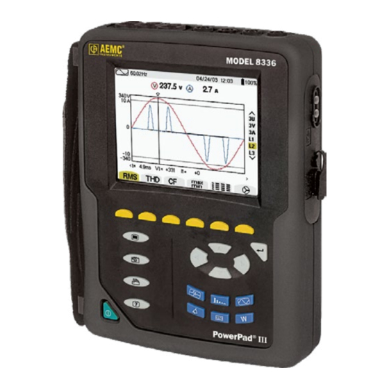
BUTTON DESCRIPTION Power / Energy: • Displays power levels and the associated parameters (power factor, dis- placement and tangent) • Energy monitoring • Four quadrant measurement to discern source/load active energy and induc- tive/capacitive reactive energy Control Features Over molded protective housing USB port LCD Display Input for external power supply... -
Page 8: Instrument Configuration
Instrument Configuration NOTE: Instrument configuration can also be modified through DataView software. ® NOTE: The instrument must be configured the first time it is used. The configuration is saved in memory when the instrument is turned OFF. Press the button to configure the unit. The following sub-menus appear: •... -
Page 9: Getting Started
PARAMETER FUNCTION Probes and Ratios Defines the type of current probe to connect • MN93: 200 A • MN193: 100 A or 5 A (with variable ratio) • SR193: 1000 A • J93: 3500 A /5000 A • *AmpFlex Sensors: 100 A/6500 A/10,000 A ®... -
Page 10: Installation Of The Leads And Current Sensors
Installation of the Leads and Current Sensors Color-coded ID markers are supplied with the PowerPad to identify the leads and input ® terminals. • Detach the appropriate inserts from the color-coded marker and place them in the holes provided under the terminals (larger inserts for current terminals, smaller inserts for voltage terminals). -
Page 11: Replacing The Battery
Replacing the Battery TO ELIMINATE ALL RISK OF ELECTRIC SHOCK, DISCONNECT THE POWER SUPPLY CORD AND MEASUREMENT LEADS FROM THE INSTRUMENT. 1. Turn the instrument over, raise the stand, and prop it up. 2. Use a coin to unscrew the two quarter-turn screws on the back of the housing. 3. -
Page 12: Repair And Calibration
Repair and Calibration To ensure that your instrument meets factory specifications, we recommend that it be sent back to our factory Service Center at one-year intervals for recalibration or as required by other standards or internal procedures. For instrument repair and calibration: You must contact our Service Center for a Customer Service Authorization Number (CSA#). -
Page 13: Limited Warranty
Limited Warranty The instrument is warrantied to the owner for a period of two years from the date of original purchase against defects in manufacture, unless the instrument was registered within 30 days of the purchase date (see warranty note below). This limited warranty is given by AEMC Instruments, not by the distributor from whom ®... - Page 14 NOTES:...
- Page 15 NOTES:...
- Page 16 03/23 99-MAN 100406 v08 AEMC Instruments ® 15 Faraday Drive • Dover, NH 03820 USA Phone: (603) 749-6434 • (800) 343-1391 • Fax: (603) 742-2346 www.aemc.com © Chauvin Arnoux , Inc. d.b.a. AEMC Instruments. All Rights Reserved. ® ®...
Need help?
Do you have a question about the Measure Up PowerPad III and is the answer not in the manual?
Questions and answers