Table of Contents
Advertisement
Quick Links
v3 - 03/02
SERVICE / CALIBRATION MANUAL
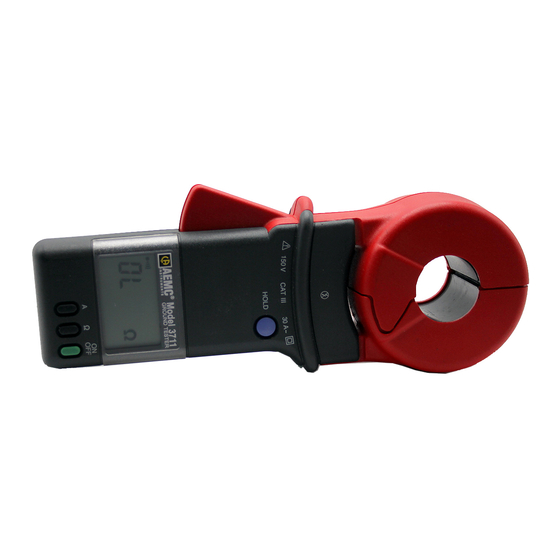
Clamp-On Ground Resistance Tester
AEMC
Model 3711/3731
®
(Chauvin Arnoux Model 6412/6415)
®
®
This document is confidential property of Chauvin Arnoux
, Inc. d.b.a. AEMC
Instruments and may not be reproduced without permission.
®
AEMC
Instruments retains the right to make changes to specifications herein at any time, without notice.
Advertisement
Table of Contents


Need help?
Do you have a question about the Chauvin Arnoux 6412 and is the answer not in the manual?
Questions and answers