
Related Manuals for AEMC instruments 606


Summary of Contents for AEMC instruments 606
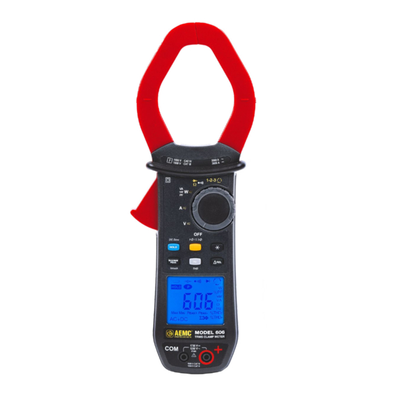
- Page 1 User Manual ENGLISH Power Clamp-On Meter Model 606 CLAMP-ON METERS WITH AEMC INSTRUMENTS ®...
- Page 2 Copyright Chauvin Arnoux , Inc. d.b.a. AEMC Instruments. All rights reserved. © ® ® No part of this documentation may be reproduced in any form or by any means (including electronic storage and retrieval or translation into any other language) without prior agreement and written consent from Chauvin Arnoux , Inc., as governed by United States and International copyright laws.
- Page 3 Statement of Compliance Chauvin Arnoux , Inc. d.b.a. AEMC Instruments ® ® certifies that this instrument has been calibrated using standards and instruments traceable to international standards. We guarantee that at the time of shipping your instrument has met the instrument’s published specifications.
-
Page 4: Table Of Contents
TABLE OF CONTENTS 1. INTRODUCTION...............7 1.1 INTERNATIONAL ELECTRICAL SYMBOLS ......... 7 1.2 DEFINITION OF MEASUREMENT CATEGORIES (CAT) ... 7 1.3 PRECAUTIONS FOR USE.............. 8 1.4 RECEIVING YOUR SHIPMENT ............. 9 1.5 ORDERING INFORMATION ............9 1.5.1 Accessories ..................9 1.5.2 Replacement Parts ................ 9 2. - Page 5 4.4 CONFIGURATION ................. 24 4.4.1 Configuring the Maximum Resistance for Continuity ....24 4.4.2 Auto Power OFF ................24 4.4.3 Configuring Current Threshold for True InRush Measurement.. 25 ® 4.4.4 Default Configuration ..............25 4.5 VOLTAGE MEASUREMENT (V) ..........26 4.6 CONTINUITY TEST .............
- Page 6 5.2.7 True InRush Measurement ............41 ® 5.2.8 Continuity Measurement ............. 42 5.2.9 Resistance Measurement ............42 5.2.10 Diode Test .................. 42 5.2.11 Active DC Power Measurements ..........43 5.2.12 Active AC Power Measurements ..........43 5.2.13 Active AC+DC Power Measurements ........44 5.2.14 Measurement of Apparent AC Power ........
-
Page 7: Introduction
Example: hardwired equipment in fixed installation and circuit breakers. CAT II: Corresponds to measurements performed on circuits directly connected to the electrical distribution system. Example: measurements on household appliances and portable tools. Clamp-On Meter Model 606 - User Manual... -
Page 8: Precautions For Use
■ As a safety measure, and to avoid repeated overloads on the inputs of the device, configuration operations should only be performed when the device is disconnected from all dangerous voltages. Clamp-On Meter Model 606 - User Manual... -
Page 9: Receiving Your Shipment
1.5 ORDERING INFORMATION Clamp-On Meter Model 606 ............Cat. #2139.62 Includes set of two color-coded silicone insulated test leads, test probes and alligator clips, soft carrying case, four 1.5 V AA batteries, and user manual. -
Page 10: Product Features
2. PRODUCT FEATURES The Clamp-On Meter Model 606 is a 10,000-count professional electrical measuring instrument that combines the following functions: ■ Current measurement ■ Measurement of Inrush current / overcurrent (True InRush ® ■ Voltage measurement ■ Frequency measurement ■ Measures harmonic distortion (THD) ■... -
Page 11: Front & Back Of Instrument
Jaws with centering marks (see connection 4.5 to 4.14 principles) Physical Guard Rotary Switch Function Buttons Backlit Display Input Terminals Trigger Battery Compartment & Compartment Screw (see § 4.1 for instructions on installing the batteries) Clamp-On Meter Model 606 - User Manual... -
Page 12: Rotary Switch
AC, DC, AC+DC current measurement (A) Power measurements (W, var, VA) and calculation of the power factor (PF) 4.11 AC, DC, AC+DC Continuity test Ω Resistance measurement Diode test Phase rotation order indicator 4.12 Clamp-On Meter Model 606 - User Manual... -
Page 13: Function Buttons
® measurement (A) Performs frequency measurements (Hz) and selects measurement of harmonic distortion (THD) Display of the powers W, VA, var and PF Activation of ΔREL mode Displays differential and relative values Clamp-On Meter Model 606 - User Manual... -
Page 14: Unit Display
Alternating and Direct current or voltage ΔREL Relative value, with respect to a reference ΔRef Reference value Storage of the values and display HOLD HOLD Maximum DC or RMS value Minimum DC or RMS value Clamp-On Meter Model 606 - User Manual... -
Page 15: Measurement Capacity Exceeded (Ol)
The display of rdy, for ready, indicates that the device is ready (Phase Order Indication function). 2.4.2 Measurement Capacity Exceeded (OL) The OL (Over Load) symbol is displayed when the display capacity is exceeded. Clamp-On Meter Model 606 - User Manual... -
Page 16: Terminals
2.5 TERMINALS The terminals are used as follows: Figure 6 Item Function COM (black) Input Terminal Jack + Positive (red) Input Terminal Jack Clamp-On Meter Model 606 - User Manual... -
Page 17: Function Buttons
(> 2 sec) or HOLD modes (short press) are first deactivated AC+DC Performs automatic lead resistance sustained compensation (See § 4.6.1) See § 3.4.2 and § 3.5.2 for the button functionality in combination with buttons. Clamp-On Meter Model 606 - User Manual... -
Page 18: Button (Second Function)
- Press again to return to the display of the single-phase power ( is off) BACKLIGHT DISPLAY BUTTON Successive presses on Function Enables/Disables display backlighting NOTE: The backlighting is automatically disabled at the end of two minutes. Clamp-On Meter Model 606 - User Manual... -
Page 19: Max/Min/Peak Button
NOTE: If the HOLD function is activated, it is not possible to exit from the MAX/MIN mode. The HOLD function must first be disabled. NOTE: The ΔREL function can be used with the functions of the MAX/MIN/PEAK mode. Clamp-On Meter Model 606 - User Manual... -
Page 20: The Max/Min/Peak Mode + Activation Of The Hold Mode
(backlighting turns OFF) NOTE: The A symbol flashes to indicate surveillance of the signal. - Second press: Exits the True InRush ® mode (returns to simple current measurement) Clamp-On Meter Model 606 - User Manual... -
Page 21: Button
- The active power (W) - Enters or exits from the level of harmonics long (> 2 sec) (THD) calculation and display mode - Selects THDf, THDr or the frequency of the then short fundamental Clamp-On Meter Model 606 - User Manual... -
Page 22: The Hz Function + Activation Of The Hold Mode
- Displays the current value. The ΔRef symbol blinks. long (> 2 sec) - Exits from ΔREL mode NOTE: The Relative mode ΔREL function can also be used with the functions of the MAX/MIN/PEAK mode. Clamp-On Meter Model 606 - User Manual... -
Page 23: Operation
■ Automatically: After ten minutes with no activity, the instrument will turn OFF. Thirty (30) seconds before the device automatically switches off, an audible signal sounds intermittently. To re-activate the device, press any button or turn the rotary switch. Clamp-On Meter Model 606 - User Manual... -
Page 24: Configuration
2. When the button is released, the device is in the voltmeter function in the normal mode. 3. To return to Auto Power OFF, turn the clamp-on meter OFF and then back ON. Clamp-On Meter Model 606 - User Manual... -
Page 25: Configuring Current Threshold For True Inrush ® Measurement
The default parameters are then restored: ƒ Continuity detection threshold = 40 Ω ƒ True InRush triggering threshold = 10 % ® Clamp-On Meter Model 606 - User Manual... -
Page 26: Voltage Measurement (V)
3. Connect the test probes or the alligator clips to the circuit or component to be measured. An audible signal is emitted if there is continuity, and the measured value is displayed on the screen. Clamp-On Meter Model 606 - User Manual... -
Page 27: Automatic Lead Resistance Compensation
3. Connect the test probes or the alligator clips to the circuit or component to be measured. The measured value is displayed on the screen. NOTE: To measure low resistance values, first perform lead resistance compensation (see § 4.6.1). Clamp-On Meter Model 606 - User Manual... -
Page 28: Diode Test
3. Connect the test probes or the alligator clips to the circuit or component to be tested. The measured value is displayed on the screen. 4. Reverse the leads on the diode and repeat the test. The measured value is displayed on the screen Clamp-On Meter Model 606 - User Manual... -
Page 29: Current Measurement (A)
AC by pressing the button. The AC symbol is displayed. 2. Clamp the jaws around the conductor to be measured. The device selects AC or DC automatically. The measured value is displayed on the screen Clamp-On Meter Model 606 - User Manual... -
Page 30: Dc Or Ac+Dc Measurement
1. The rotary switch is set to . Select DC or AC+DC by pressing button until the desired choice is reached. 2. Clamp the jaws around the conductor to be measured. The measured value is displayed on the screen. Clamp-On Meter Model 606 - User Manual... -
Page 31: Starting Current Or Overcurrent (True Inrush ® ) Measurement
In DC or AC+DC power measurement, first correct the DC zero in current (see § 4.9.2). NOTE 2: For the power factor (PF) and the powers VA and var, the measurement is possible only in AC or AC+DC. Clamp-On Meter Model 606 - User Manual... -
Page 32: Single-Phase Power Measurement
L3 phase to the L2 phase to the L3 phase to the L1 phase to the L3 phase to the L1 phase to the L2 phase The measured value is displayed on the screen. Clamp-On Meter Model 606 - User Manual... -
Page 33: Phase Rotation Mode
The ref symbol blinks on the screen. The instrument is ready to determine the reference period. When the reference period has been determined, an audible signal sounds and the ref and symbols are displayed. Clamp-On Meter Model 606 - User Manual... -
Page 34: Frequency Measurement (Hz)
2. Select AC or AC+DC by pressing the button until the desired choice is reached. button. The Hz symbol is displayed. 3. Press the 4. Connect the black lead to the COM terminal and the red lead to the terminal. Clamp-On Meter Model 606 - User Manual... -
Page 35: Frequency Measurement (A)
In the balanced three-phase AC or AC+DC Power (W) setting, it is possible to display the frequency of the phase-to-phase voltage of the signal on the terminals. Clamp-On Meter Model 606 - User Manual... -
Page 36: Measurement Of Level Of Harmonics (Thd) And Frequency Of Fundamental (Network)
4. Connect the black lead to the COM terminal and the red lead to terminal. 5. Connect the test probes or the alligator clips to the terminals of the circuit to be measured. The measured value is displayed on the screen. Clamp-On Meter Model 606 - User Manual... -
Page 37: Measurement Of Thd And Frequency Of Fundamental (A)
To select the frequency of the fundamental, again press the button. The Hz symbol is displayed. 4. Clamp the jaws around the conductor to be measured. The measurement value is displayed on the screen. Clamp-On Meter Model 606 - User Manual... -
Page 38: Specifications
The display indicates +OL above + 3400 V and -OL below - 3400 V, in REL mode. Above 1700 V, a repetitive beep indicates that the voltage being measured is greater than the safety voltage for which the device is guaranteed. Clamp-On Meter Model 606 - User Manual... -
Page 39: Ac Voltage Measurement
Specific Specifications in PEAK mode in voltage (from 10 Hz to 1 kHz in AC and AC+DC): ƒ Accuracy: add 1.5 % R to the values in the tables above. ƒ PEAK capture time: 1 ms min to 1.5 ms max. Clamp-On Meter Model 606 - User Manual... -
Page 40: Dc Current Measurement
The display indicates OL above 3000 A in PEAK mode. The - and + signs are not displayed. Bandwidth in AC = 1 kHz In AC, any value between zero and the min threshold of the measurement range (0.25 A) is forced to on the display. Clamp-On Meter Model 606 - User Manual... -
Page 41: Ac+Dc Intensity Measurement
(from 10 Hz to 1 kHz ® in AC): ƒ Accuracy: add ± (1.5 % R +0.5 A) to the values of the table above. ƒ PEAK capture time: 1 ms min to 1.5 ms max. Clamp-On Meter Model 606 - User Manual... -
Page 42: Continuity Measurement
± (1 % R + 10 cts) Resolution 0.001 V Measurement Current 0.55 mA Indication: Junction reversed OL is displayed when the measured voltage >3.199 V or open-circuit NOTE: The sign is disabled for the diode test function. Clamp-On Meter Model 606 - User Manual... -
Page 43: Active Dc Power Measurements
Add + 1 % for 10 % < THD < 20 % Add + 3 % for 20 % < THD < 30 % Add + 5 % for 30 % < THD < 40 % Clamp-On Meter Model 606 - User Manual... -
Page 44: Active Ac+Dc Power Measurements
Resolution 10 W 100 W 1000 W (1) Bandwidth in AC: in voltage = 3 kHz, in current = 1 kHz (2), (3), (4), 5, 6 and (7) of the previous § apply. Clamp-On Meter Model 606 - User Manual... -
Page 45: Measurement Of Apparent Ac Power
Display of O.L above 5100 kVA in single-phase (1700 V x 3000 A). Bandwidth in AC: in voltage = 3 kHz, in current = 1 kHz (2), (3) and (4) of the previous § apply. Clamp-On Meter Model 606 - User Manual... -
Page 46: Measurement Of Reactive Ac Power
( see § 5.2.12.1): Quadrant 1: Reactive power Q sign + Quadrant 2: Reactive power Q sign + Quadrant 3: Reactive power Q sign - Quadrant 4: Reactive power Q sign - Clamp-On Meter Model 606 - User Manual... -
Page 47: Measurement Of Reactive Ac+Dc Power
(1) If one of the terms in the calculation of the power factor is displayed as O.L, or forced to zero, the display of the power factor is an indeterminate value (7), of the previous § applies. Clamp-On Meter Model 606 - User Manual... -
Page 48: Frequency Measurement
10 Hz to 1 kHz in current): ƒ Accuracy: add 1 % R to the values of the table above. ƒ Capture time of the extrema: approximately 100 ms. Clamp-On Meter Model 606 - User Manual... -
Page 49: Specifications In Thdr
(-20 to +55) °C (-40 to +70) °C ≤ 90 % to 131 °F ≤ 90 % to 158 °F Relative Humidity (RH) (≤ 90 % to 55 °C) (≤ 90 % to 70 °C) Clamp-On Meter Model 606 - User Manual... -
Page 50: Mechanical Specifications
0.1 % R + 1 ct 0.1 % R + 2 cts Humidity (10 to 90) % RH Ω 0.2 % R 0.3 % R + 2 cts 0.25 % R 0.5 % R + 2 cts Clamp-On Meter Model 606 - User Manual... - Page 51 3 % R + 1 ct AC-AC+DC Peak factor 3000 A peak 1 % R 3 % R + 1 ct AC-AC+DC 1600 V peak * in Temperature for measurement A: Influence specified until 1000 A Clamp-On Meter Model 606 - User Manual...
-
Page 52: Maintenance
(see § 4.1). 4. Remove the used batteries and replace them with (4) 1.5 V AA batteries, observing the polarities. 5. Close the battery compartment cover and screw it onto the housing. Clamp-On Meter Model 606 - User Manual... -
Page 53: Repair And Calibration
Chauvin Arnoux , Inc. d.b.a. AEMC Instruments ® ® Phone: (800) 343-1391 (Ext. 351) Fax: (603) 742-2346 E-mail: techsupport@aemc.com www.aemc.com Clamp-On Meter Model 606 - User Manual... -
Page 54: Limited Warranty
(603) 749-6434 (Ext. 360) Fax: (603) 742-2346 E-mail: repair@aemc.com Caution: To protect yourself against in-transit loss, we recommend that you insure your returned material. NOTE: You must obtain a CSA# before returning any instrument. Clamp-On Meter Model 606 - User Manual... - Page 55 NOTES:...
- Page 56 03/24 99-MAN 100585 v00 AEMC Instruments ® 15 Faraday Drive • Dover, NH 03820 USA Phone: +1 (603) 749-6434 • +1 (800) 343-1391 • Fax: +1 (603) 742-2346 www.aemc.com © 2024 Chauvin Arnoux , Inc. d.b.a. AEMC Instruments. All Rights Reserved. ®...
Need help?
Do you have a question about the 606 and is the answer not in the manual?
Questions and answers