Table of Contents
Advertisement
Quick Links
Advertisement
Table of Contents

Subscribe to Our Youtube Channel
Related Manuals for Topcon TRC-NW200


Summary of Contents for Topcon TRC-NW200
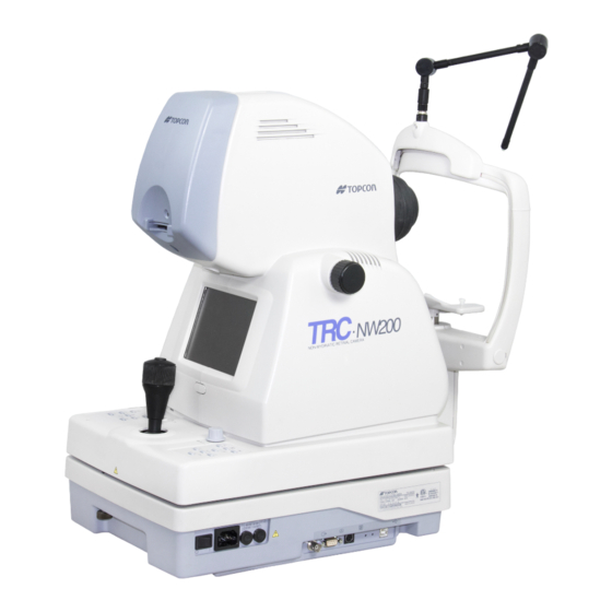
- Page 1 INSTRUCTION MANUAL NON-MYDRIATIC RETINAL CAMERA TRC- NW200...
-
Page 2: Introduction
Before using the instrument, carefully read the "DISPLAY FOR SAFE USE" and the "SAFETY CAUTIONS" to familiarize yourself with the features of the TRC-NW200 Non-Mydriatic Retinal Camera and to ensure that you operate it efficiently and safely. - Page 3 CAUTIONS FOR USE Basic caution When moving the chinrest up and down, be careful not to catch the patient's hand. [The patient may be injured.] ENVIRONMENTAL CONDITIONS FOR USE Temperature: 10°C ~ 40°C Humidity: 30% ~ 75% (without dew condensation) Air pressure: 700hPa ~ 1060hPa STORAGE, USAGE PERIOD AND OTHERS 1.
-
Page 4: Display For Safe Use
DISPLAY FOR SAFE USE To encourage safe and proper use and to prevent danger to the operator and others or poten- tial damage to properties, important messages are put on the instrument body and inserted in the instruction manual. We suggest that everyone understand the meaning of the following displays, icons and text before reading the "SAFETY CAUTIONS"... -
Page 5: Safety Cautions
SAFETY CAUTIONS WARNINGS Icon Prevention item Page To avoid electric shock, be sure to unplug the power cable before assembling. Also, do not plug the power cable in before assembling. To avoid fire and electric shock in case of leakage, be sure to use a power supply equipped with a 3-plug AC receptacle for proper grounding. - Page 6 SAFETY CAUTIONS CAUTIONS Icon Prevention item Page To avoid pain and discomfort to the patient and/or damage to the patient's eye, do not brighten the monitor lamp more than necessary. To avoid pain and discomfort to the patient and/or damage to the patient's eye, do not brighten the photography light more than necessary.
- Page 7 SAFETY CAUTIONS CAUTIONS Icon Prevention item Page Adjust the height of the chinrest while watching the patient directly. To avoid injury to the patient's eyes and nose while moving the instrument body, be attentive of the distance between the patient and the objective lens. To avoid falling and injury while moving the table with the instrument on top of it, be sure to use an approved automatic instrument table.
-
Page 8: Usage And Maintenance
USAGE AND MAINTENANCE USAGE Usage: • The TRC-NW200 Non-Mydriatic Retinal Camera is an electric instrument for medical use. Use this instrument under a doctor's guidance. USER MAINTENANCE To ensure the safety and performance of the instrument, all maintenance work, unless specified in this manual, shall be conducted by trained service engineers. -
Page 9: Warning Displays And Positions
WARNING DISPLAYS AND POSITIONS To ensure safety, the machine provides warning displays. Use the instrument correctly by observing the display instructions. If any of the following display labels are missing, contact your TOPCON dealer at the address listed on the back cover. CAUTION... -
Page 10: Table Of Contents
CONTENTS Introduction ........................1 Display for safe use .......................3 Safety cautions ......................4 Usage and maintenance ....................7 Escape clauses......................7 Warning displays and positions..................8 COMPONENTS Component names....................... 11 Composition of parts which contact the human body........... 11 Control panel components ...................12 Monitor screen ......................13 Standard accessories....................15 ASSEMBLY Components.........................16... - Page 11 Anterior segment photography..................84 Playback and deletion of recorded image..............85 PC mode ........................87 Finishing........................87 BEFORE REQUESTING SERVICE Troubleshooting ......................88 SPECIFICATIONS AND PERFORMANCE Specifications .......................90 Electromagnetic compatibility ..................90 Electric rating .......................90 System classification....................91 Dimensions and weight....................91 Purpose of use......................91 Operation principle.......................91 MAINTENANCE Daily checkups......................92 Cleaning........................98 Disposing the product ....................99...
-
Page 12: Components
COMPONENTS COMPONENT NAMES Connector Access lamp Diopter compensation lens selector Focusing knob Color video monitor Image quality adjustment knob Photography switch IR filter selector Omni-directional joystick Control panel Base brake knob Vertical position mark Power lamp Fuse holder Fixing knob (for carrying) Forehead rest Objective lens Canthus marker... -
Page 13: Control Panel Components
CONTROL PANEL COMPONENTS Thumbnail switch Fixation target Mode selector knob Picture angle switch Menu switch Split switch selector switch Flash level switch (-, reset, +) No. switch Illumination level switch (-, +) Menu switch ........Displays the Menu screen. Split switch ........Turns the split lines on/off. Flash level switch...... -
Page 14: Monitor Screen
MONITOR SCREEN Monitor screen Patient ID File name Rest of frames Xenon charging display Right/left eye ( ) scale Flash level compensation display Alignment bright spots Flash level display Split lines Picture angle display Fixation target position display Illumination level T C N Menu screen MAIN MENU... - Page 15 Preview display (color) Right/left eye Patient ID File name Photography image Date Picture angle 45° Digital zoom (×2) Digital zoom (×4) In the case of digital zoom (×2), the mask may not be indicated at the center of the review display on the monitor, and it may be partly missing. However, the recorded image is not affected by this phenomenon.
-
Page 16: Standard Accessories
32MB (1) USB cable (1) Chinrest tissue paper (1) Chinrest tissue pin (2) Instruction manual (1) Spare parts case (1) Dust cover (1) Cord bracket (1) TRC-NW200 Software Kit TRC-NW200 Software Kit Setup disk (1) Instruction manual (1) COMPONENTS... -
Page 17: Assembly
Spare parts case (4) Phillips screwdriver (12) Fuse (spare) Spare parts case ® (5) CompactFlash card 32MB Spare parts case (13) TRC-NW200 Instruction Manual (6) USB cable (14) TRC-NW200 Software Kit Setup disk (7) Cord bracket (15) TRC-NW200 Software Kit Instruction manual... -
Page 18: Assembly Procedure
ASSEMBLY PROCEDURE ASSEMBLING THE INSTRUMENT BODY To avoid electric shock, be sure to unplug the power cable WARNING before assembling. Also, do not plug the power cable in before assembling. To prevent the instrument from falling and to avoid injury, CAUTION do not install the instrument on an uneven or unsteady surface, including a slope. - Page 19 Remove the Styrofoam from the transportation bracket (A) (the one on the left-hand side as viewed from the chinrest side). Move the base to the left and unscrew the transportation bracket (B) with a screwdriver. Transportation bracket (B) Transportation bracket (A) Slide the base to the right and unscrew the transportation bracket (A) with the screwdriver.
-
Page 20: Confirmation After Assembly
CONFIRMATION AFTER ASSEMBLY Slide the base to the left, as viewed from the operator side, and make sure that the voltage selector is set at 100V. 220V 100V 240V 120V VOLTAGE SELECTOR Set at the left-end Set at the left-end Make sure that the input voltage is within the range ±10% of 100V. -
Page 21: Preparations
PREPARATIONS INSTALLING THE INSTRUMENT To prevent the instrument from falling and to avoid injury CAUTION during carrying, be sure to secure the instrument with the fixing knob at the bottom. To avoid injury during carrying, be sure to hold the instru- ment body at the bottom with two people. -
Page 22: Connecting The Power Cable
If the instrument body is slightly off level, fine-adjust the height by properly operating the four adjusters. Do not extend the adjuster past 1cm. Adjuster CONNECTING THE POWER CABLE To avoid fire and electric shock in case of leakage, be sure WARNING to use a power supply equipped with a 3-plug AC recepta- cle for proper grounding. -
Page 23: Installation Of The Compactflash Card
® Use the CompactFlash card specified by TOPCON. ® Refer to "OPTIONAL ACCESSORIES" on P.100 for the CompactFlash card description. -
Page 24: Removal Of The Compactflash Card
® REMOVAL OF THE COMPACTFLASH CARD ® Before removing the CompactFlash card, make sure that NOTE the switch on the instrument is in the "OFF" (O) position. Make sure that the switch on the instrument is in the "OFF" (O) position. ®... -
Page 25: Connecting The External Device
Fit the USB cable into the clamp of the cord bracket. Clamp Opening Use the USB cable specified by TOPCON (accessory). The USB cable may not connect to all PC's, so please ensure the connection is correct before attempting to fit the plug. Contact your authorized dealer for any assistance regarding the USB connection. - Page 26 Image output to an external monitor and others Through the image output port on the external connection terminal, the image displayed on the color video monitor can be displayed on an external monitor. Connect the BNC cable (optional) to the image output terminal 1 of this instrument.
-
Page 27: Menu Setting
MENU SETTING On the "MAIN MENU" display, setting of internal fixation target, switching of inter- nal/external fixation target, flash level, setting of built-in CCD camera, setting of ID number and setting of AE can be selected. Preparation for menu setting Check the power cable connection. -
Page 28: Setting The Internal Fixation Target
SETTING THE INTERNAL FIXATION TARGET In setting of the internal fixation target, fixation target on/flicker status and fixation target pattern can be set. Switching of internal fixation target on/flicker The internal fixation target can be switched between on and flicker states. When shipped, "FLICKERING"... - Page 29 Internal fixation target pattern You can select the internal fixation target pattern from two types, "ORIGINAL" (default pattern ) and "CUSTOM" (pattern to be set optionally). When shipped, "ORIGINAL" is set. Move the cursor to "FIXATION PATTERNS" on the "FIXATION" screen and press the to access the "FIXATION PAT- FLASH LEVEL SWITCH (RESET)
- Page 30 Setting of "PATTERNS" when changing "MODE" to "ORIGINAL" When you select "ORIGINAL" on the "MODE" screen, you can select the internal fixation target patterns (P2A/P2B/P3A/P3B) of "center/nose side/ear side" on the "PATTERNS" screen. When "P2A" or "P2B" is selected, the fixation targets for "center/nose side" are indicated. When "P3A"...
-
Page 31: Setting The Flash Level
SETTING THE FLASH LEVEL You can set the flash level. Flash level You can change the standard or zero value of the flash level. When shipped, "0" (no change) is set. Select "FLASH LEVEL" on the "MAIN MENU" screen, and press the to call out the "FLASH LEVEL"... -
Page 32: Setting The Built-In Ccd Camera
SETTING THE BUILT-IN CCD CAMERA In the "CAMERA" display menu, the compression ratio, record pixels, gain, white balance, image emphasis, contrast, color, CF format, PC mode, image name, date/time, date form, file protect function and print can be set. Move the cursor to "CAMERA" on the "MAIN MENU" display and press the FLASH LEVEL SWITCH (RESET) The Monitor display changes to the "CAMERA"... - Page 33 Record pixels Set the size of the image to be recorded. When shipped, "FULL" is set. Select "SIZE" on the "CAMERA" display. The "SIZE" display appears. SIZE FULL UXGA XGA Press the and select FLASH LEVEL SWITCH (+) FLASH LEVEL SWITCH (-) the desirable size from the following: "FULL"...
- Page 34 White balance The color balance of the image can be changed. The three types, "WHITE BAL. 1", "WHITE BAL. 2" and "WHITE BAL. 3" can be stored. When shipped, "R-GAIN 96/G-GAIN 70/B-GAIN 85" of "WHITE BAL. 1" is set. Select "WHITE BAL." on the "CAMERA" display. The "WHITE BAL." dis- play appears.
- Page 35 Image emphasis Image emphasis allows you to change certain image characteristics. When shipped, "0" is set. Select "ENHANCE" on the "CAMERA" display. The "ENHANCE" display appears. ENHANCE LEVEL 0 Press the and change FLASH LEVEL SWITCH (+) FLASH LEVEL SWITCH (-) the level to the desirable one.
- Page 36 Color The image color depth can be changed. When shipped, "0" is set. Select "COLOR" on the "CAMERA" display. The "COLOR" display appears. COLOR LEVEL 0 Press the and adjust FLASH LEVEL SWITCH (+) FLASH LEVEL SWITCH (-) the image color depth. The color depth can be adjusted by 9 steps, from "-4"...
- Page 37 PC mode You can select the operation mode for the PC mode of the mode selector knob. When shipped, "SHOOTING" is set. Select "PC MODE" on the "CAMERA" display. The "PC MODE" display appears. PC MODE STORAGE SHOOTING Press the and select FLASH LEVEL SWITCH (+) FLASH LEVEL SWITCH (-) "STORAGE"...
- Page 38 Image name You can select the record number mode of the image file to be recorded. Select "IMAGE NAME" on the "CAMERA" display. The "IMAGE NAME" display appears. IMAGE NAME MODE NAME Press the and select FLASH LEVEL SWITCH (+) FLASH LEVEL SWITCH (-) "MODE"...
- Page 39 Date/time You can set the date and time. Select "DATE" on the "CAMERA" display. The "DATE" display appears. DATE 04‑04‑20 17:36 Press the and move FLASH LEVEL SWITCH (+) FLASH LEVEL SWITCH (-) the cursor to the item to be set. Press the FLASH LEVEL SWITCH (+) FLASH LEVEL SWITCH (-)
- Page 40 File protect function You can set the file protection setting for the camera. Select "FILE PROTECT" on the "CAMERA" display. The "FILE PRO- TECT" display appears. FILE PROTECT ALL SET RESET EXIT Press the and select FLASH LEVEL SWITCH (+) FLASH LEVEL SWITCH (-) "ALL SET"...
-
Page 41: Setting The Id Number
Print ® For the image stored in the CompactFlash card, DPOF print can be reserved. Select "PRINT" on the "CAMERA" display. The "PRINT" display appears. PRINT RESERVATION DATE INDEX Press the and select FLASH LEVEL SWITCH (+) FLASH LEVEL SWITCH (-) "RESERVATION", "DATE"... -
Page 42: Setting Of Ae
In a few seconds, the color video monitor is displayed and ready for photo- graphing. When shipped, the power save set time is 10 minutes. To change the set time, contact your dealer or TOPCON (see the back cover). PREPARATIONS... -
Page 43: Initial Setting
INITIAL SETTING In the "INITIAL MENU" display, the record/playback, internal fixation target, image display, system settings, initial settings, built-in CCD camera settings and display language can be set. PREPARATION FOR INITIAL SETTING Make sure that the power cable is connected. While pressing the on the control panel and the MENU SWITCH... -
Page 44: Setting The Internal Fixation Target
SETTING THE INTERNAL FIXATION TARGET On the "FIXATION" display, fixation target on/flicker status and fixation target pat- tern can be set. On the "INITIAL MENU" screen, move the cursor to "FIXATION," and press . The Monitor screen changes to the FLASH LEVEL SWITCH (RESET) "FIXATION"... -
Page 45: Switching Of Internal/External Fixation Target (Option)
SWITCHING OF INTERNAL/EXTERNAL FIXATION TARGET (OPTION) You can change the internal/external fixation target. When shipped, "INTERNAL" (internal fixation target) is the default setting. Move the cursor to "INTERNAL/EXTERNAL FIX" on the "FIXATION" screen and press the to access the "INTER- FLASH LEVEL SWITCH (RESET) NAL/EXTERNAL FIX"... - Page 46 Press the on the FLASH LEVEL SWITCH (+) FLASH LEVEL SWITCH (-) "MODE" screen and select "ORIGINAL" or "CUSTOM". MODE ORIGINAL CUSTOM Setting of "PATTERNS" when changing "MODE" to "ORIGINAL" When you select "ORIGINAL" on the "MODE" screen, you can select the internal fixation target patterns (P2A/P2B/P3A/P3B) of "center/nose side/ear side"...
- Page 47 Setting of "PATTERNS" when changing "MODE" to "CUSTOM" When you select "CUSTOM" on the "MODE" screen, you can set the internal fixation target pattern optionally on the "PATTERNS" screen. You can freely set a fixation target position for the photography with optic disc or macula in focus.
-
Page 48: Setting The Screen Display
SETTING THE SCREEN DISPLAY In the "MONITOR DISPLAY" menu, the flash level compensation display, flash level display, illumination level display, picture angle display, fixation target posi- tion and date display can be set. Make sure that the cursor is on the "MONITOR DISPLAY" of the "INITIAL MENU"... - Page 49 Flash level display The flash level may be displayed on the monitor. When shipped, "OFF" (no dis- play) is set. Select "FLASH LEVELS IN WS" on the "MONITOR DISPLAY" screen, and choose the "FLASH LEVELS IN WS" screen. FLASH LEVELS IN WS ON OFF Press the and select...
- Page 50 Picture angle display The picture angle may be displayed on the monitor. When shipped, "ON" (dis- play) is set. Select "ANGLE INDICATION" on the "MONITOR DISPLAY" screen, and select the "ANGLE INDICATION" screen. ANGLE INDICATION ON OFF Press the and select FLASH LEVEL SWITCH (+) FLASH LEVEL SWITCH (-) "ON"...
- Page 51 Image name The DCF file name may be displayed on the monitor. When shipped, "OFF" (no display) is set. Select "IMAGE NAME" on the "MONITOR DISPLAY" screen and access the "IMAGE NAME" screen. IMAGE NAME ON OFF Press the and select FLASH LEVEL SWITCH (+) FLASH LEVEL SWITCH (-) "ON"...
- Page 52 The right/left eye information may be displayed on the monitor. When shipped, "ON" (display) is set. Select "RL" on the "MONITOR DISPLAY" screen and access the "RL" dis- play. ON OFF Press the and select FLASH LEVEL SWITCH (+) FLASH LEVEL SWITCH (-) "ON"...
- Page 53 Date display The date may be displayed on the monitor. When shipped, "ON" (display) is set. Select "DATE" on the "MONITOR DISPLAY" screen and access the "DATE" display. DATE ON OFF Press the and select FLASH LEVEL SWITCH (+) FLASH LEVEL SWITCH (-) "ON"...
-
Page 54: System Setting
SYSTEM SETTING In the "SYSTEM SETTINGS" display, the recording method can be set. When shipped, “TYPE1 MODE” (When taking a picture, recording is done and reviewing is released.) is set. Make sure that the cursor is on the "SYSTEM SETTINGS" of the "INITIAL MENU"... -
Page 55: Setting The Initial State
SETTING THE INITIAL STATE In the "INITIAL SETTINGS" menu, the flash level, operation sound, power saver time, split switch, trigger out and AE can be set. Make sure that the cursor is on the "INITIAL SETTINGS" of the "INITIAL MENU" screen, and press the . - Page 56 Operation sound The operation sound may be turned on or off. When shipped, "ON" (operation sound) is set. Select "OPERATION SOUND" on the "INITIAL SETTINGS" screen, and call out the "OPERATION SOUND" screen. OPERATION SOUND ON OFF Press the and select FLASH LEVEL SWITCH (+) FLASH LEVEL SWITCH (-) "ON"...
- Page 57 Split switch function You can select whether the split lines are ON or OFF, whether the internal fixation tar- get is ON or OFF and whether the white balance setting pattern is changed or not. When shipped, "SPLIT" (split ON/OFF) is set. Select "SPLIT SWITCH"...
- Page 58 Trigger out The trigger signal output for an external recording device can be selected. When shipped, "OFF" (no output) is set. Select "TRIGGER OUT" on the "INITIAL SETTINGS" display. The "TRIG- GER OUT" display appears. TRIGGER OUT ON OFF Press the and select FLASH LEVEL SWITCH (+) FLASH LEVEL SWITCH (-)
-
Page 59: Setting The Built-In Ccd Camera
SETTING THE BUILT-IN CCD CAMERA In the "CAMERA" display menu, the compression ratio, record pixels, gain, white balance, image emphasis, contrast, color, CF format, PC mode, image name, date/time, date form, file protect and print can be set. Move the cursor to "CAMERA" on the "INITIAL MENU" display and press . - Page 60 Record pixels You can set the size of the image to be recorded. When shipped, "FULL" is set. Select "SIZE" on the "CAMERA" display. The "SIZE" display appears. SIZE FULL UXGA XGA Press the and select FLASH LEVEL SWITCH (+) FLASH LEVEL SWITCH (-) the desirable size from the following: "FULL"...
- Page 61 White balance The color balance of the image can be changed. The three types, "WHITE BAL. 1", "WHITE BAL. 2" and "WHITE BAL. 3" can be stored. When shipped, "R-GAIN 96/G-GAIN 70/B-GAIN 85" of "WHITE BAL. 1" is set. Select "WHITE BAL." on the "CAMERA" display. The "WHITE BAL." dis- play appears.
- Page 62 Image emphasis Image emphasis allows you to change certain image characteristics. When shipped, "0" is set. Select "ENHANCE" on the "CAMERA" display. The "ENHANCE" display appears. ENHANCE LEVEL 0 Press the and change FLASH LEVEL SWITCH (+) FLASH LEVEL SWITCH (-) the level to the desirable one.
- Page 63 Color The image color depth can be changed. When shipped, "0" is set. Select "COLOR" on the "CAMERA" display. The "COLOR" display appears. COLOR LEVEL 0 Press the and adjust FLASH LEVEL SWITCH (+) FLASH LEVEL SWITCH (-) the image color depth. The color depth can be adjusted by 9 steps, from "-4" to "+4".
- Page 64 PC mode You can select the operation mode for the PC mode of the mode selector knob. When shipped, "SHOOTING" is set. Select "PC MODE" on the "CAMERA" display. The "PC MODE" display appears. PC MODE STORAGE SHOOTING Press the and select FLASH LEVEL SWITCH (+) FLASH LEVEL SWITCH (-) "STORAGE"...
- Page 65 Image name You can select the record number mode of the image file to be recorded. Select "IMAGE NAME" on the "CAMERA" display. The "IMAGE NAME" display appears. IMAGE NAME MODE NAME Press the and select FLASH LEVEL SWITCH (+) FLASH LEVEL SWITCH (-) "MODE"...
- Page 66 Date/time You can set the date and time. Select "DATE" on the "CAMERA" display. The "DATE" display appears. DATE 04‑04‑20 17:36 Press the and move FLASH LEVEL SWITCH (+) FLASH LEVEL SWITCH (-) the cursor to the item to be set. Press the FLASH LEVEL SWITCH (+) FLASH LEVEL SWITCH (-)
- Page 67 File protect function You can set the file protection setting for the camera. Select "FILE PROTECT" on the "CAMERA" display. The "FILE PROTECT" display appears. FILE PROTECT ALL SET RESET EXIT Press the and select FLASH LEVEL SWITCH (+) FLASH LEVEL SWITCH (-) "ALL SET"...
- Page 68 Print ® For the image stored in the CompactFlash card, DPOF print can be specified. Select "PRINT" on the "CAMERA" display. The "PRINT" display appears. PRINT RESERVATION DATE INDEX Press the and select FLASH LEVEL SWITCH (+) FLASH LEVEL SWITCH (-) "RESERVATION", "DATE"...
-
Page 69: Setting The Id Number
Backup ® Data are recorded in the CompactFlash card and at the same time can be sent to PC through USB. When shipped, "OFF" (data are not sent) is set. Select "BACKUP" on the "CAMERA" display. The "BACKUP" display appears. BACKUP ON OFF... - Page 70 COUNTER : ON/OFF for the 4-digit calculation counter attached to the ID number can be selected. COUNTER ON OFF COUNTER MODE : The mode of the 4-digit calculation counter attached to the ID number can be selected. COUNTER MODE NON‑CONTINUATION CONTINUATION COUNTER DATA : The data of the 4-digit calculation counter attached to the ID number can be set.
-
Page 71: Setting The Language
SETTING THE LANGUAGE On the "LANGUAGE" screen, the language to be used on the MENU screen can be set. When shipped, "ENGLISH" is set. Make sure that the cursor is on the "LANGUAGE" of the "INITIAL MENU" screen, and press the . -
Page 72: Basic Operations
BASIC OPERATIONS PREPARATION FOR PHOTOGRAPHY Applying the power supply Carefully check the power cable connection. For details about the connection, see "CONNECTING THE POWER CABLE" on page 21. ® Install the CompactFlash card. For details of the installation, see ® "INSTALLATION OF THE COMPACTFLASH CARD"... - Page 73 When changing the photography mode to the input mode with the , press the for 1 second or more. The ID No. SWITCH (Num) No. SWITCH (Num) numbers can be reset to the initial values (zero). [Example of input] 12345678_0001 (Display) ⇒ 12525678-0001 (Change) [Display and procedure] (When the No.
- Page 74 Make sure that the IR filter selector is pushed in. IR filter selector being pushed in Seat the patient comfortably in an exam stool or exam chair in front of the instrument. Adjust the table height or chair height so the patient can relax with his/her chin placed centrally on the chinrest.
-
Page 75: Color Photography (Center)
COLOR PHOTOGRAPHY (CENTER) To ensure correct imaging, adjust the table height so the NOTE patient can relax with his/her chin placed centrally on the chinrest. Setting the picture position Set the photography position with the FIXATION TARGET SELECTOR SWITCH Press the , and the target position is adjusted. - Page 76 See the "Flash level" on page 30. The flash level display can also display the light intensity level (unit: WS) in addi- tion to the compensation value. For details about the flash level setting, contact your dealer or TOPCON (see the back cover). BASIC OPERATIONS...
- Page 77 Changing the diopter compensation lens Pull out the diopter compensation lens selector and change the diopter compen- sation lens for the patient's eye. When the patient's eye has a strong myopia, pull out the diopter compensation lens selector by one step and set it to (-). When the patient's eye has a strong hyperopia, pull out the diopter compensation lens selector by two steps and set it to (+).
- Page 78 Alignment and photography To avoid injury, do not place your fingers into the gap CAUTION between the instrument body and the power supply unit. To avoid injury to the patient's eyes and nose while mov- CAUTION ing the instrument body, be attentive of the distance between the patient and the objective lens.
- Page 79 Hold the omni-directional joystick and pull the instrument backwards toward the operator. As the internal fixation target turns on, instruct the patient to look at the fixation target in the center. Observe the anterior segment image on the color video monitor. Move the instrument body in right and left / up and down directions until you get the patient's eye in the center of the color video monitor.
- Page 80 While keeping the joystick upright, bring the base closer to the patient; the retina image appears on the color video monitor. Instruct the patient to look at the green light (internal fixation target). While watching the image on the color video monitor, adjust the brightness of the image using the ILLUMINATION LEVEL SWITCH For details about the illumination level setting, see page 75.
- Page 81 Operate the joystick and move the instrument body to bring the bright spot on the color video monitor into the ( ) scale. Split lines Operate the focusing knob and align the focusing split lines into one line on the color video monitor. Split lines If you cannot align the split lines into one line by operating the focusing knob, change the diopter compensation lens.
- Page 82 CompactFlash card. (TYPE2 MODE) The captured ® image can be displayed only while data is being written on the CompactFlash card. (TYPE3 MODE). To alter to these modes, contact your dealer or TOPCON (see the back cover). BASIC OPERATIONS...
-
Page 83: Photography Of Ear Side/Nose Side
PHOTOGRAPHY OF EAR SIDE/NOSE SIDE Setting the picture position To set the ear side and nose side, press the FIXATION TARGET SELECTOR SWITCH Each time it is pressed, the internal fixation target moves and the set point flickers on the color video monitor. Set to "N"... - Page 84 Alignment and photography The alignment operation is done with the omni-directional joystick. For details about movement/adjustment of the instrument body with the omni-directional joystick, see the "MEMO" on page 77. Move the instrument body right and left or up and down to display the patient’s eye at the center of the color video monitor.
-
Page 85: Anterior Segment Photography
ANTERIOR SEGMENT PHOTOGRAPHY Setting the picture position Set the internal fixation target in the center by pressing the FIXATION TARGET SELECTOR SWITCH See "Setting the picture position" on page 74. Setting the illumination level Set the illumination level by pressing the ILLUMINATION LEVEL SWITCH See "Setting the illumination level"... -
Page 86: Playback And Deletion Of Recorded Image
No. SWITCH (Num) to decide the selected data. To delete an image through a computer, contact your dealer. ® Use the CompactFlash card specified by TOPCON. ® Refer to "OPTIONAL ACCESSORIES" on P.100 for the CompactFlash card description. If the image does not appear normally, contact your dealer for assistance. - Page 87 Playback zoom The photography image can be enlarged and displayed. Press the in the playback mode. PICTURE ANGLE SWITCH ( Each time the is pressed, the magnification is PICTURE ANGLE SWITCH ( changed, "1×" to "2×" to "4×". The enlarged image can be moved by the No.
-
Page 88: Pc Mode
PC MODE To transfer an image, turn the mode selector knob to set at "PC mode" ( For the details of the PC mode operation, refer to the standard accessory, "TRC- NW200 Software Kit Instruction Manual". ® When the PC mode is set, images are not recorded in the CompactFlash card. -
Page 89: Before Requesting Service
If, after following the instructions below, you still cannot restore the instrument to a normal condition or if the problem does not fall into any of the categories below, contact your dealer or TOPCON (see the back cover). Check List... - Page 90 Trouble Condition Check Page • Image contrast is not good. Color video monitor is Adjust contrast (contrast control). not clear. • Image is dark. Adjust brightness (brightness control). Adjust light intensity (Illumination Level switch). Darken room and thoroughly dilate patient's pupil. •...
-
Page 91: Specifications And Performance
SPECIFICATIONS AND PERFORMANCE SPECIFICATIONS Picture angle 45°, Digital zoom is possible. (×2/×4) Working range 40.7mm φ4.0mm or more when 45° is set. φ3.7mm or more when the digital zoom is Minimum pupil diameter set. Diopter compensation range No compensation lens -13D ~+12D Using (-) compensation lens -12D ~-33D Using (+) compensation lens +9D ~+40D... -
Page 92: System Classification
(in case of Class Iepuipment). • Degree of protection against harmful ingress of water: IPx0 TRC-NW200 has no protection against ingress of water. (The degree of pro- tection against harmful ingress of water defined in IEC 60529 is IPx0.) •... -
Page 93: Maintenance
• When not in use, always turn the OFF. POWER SWITCH Ordering consumables • When ordering consumables and spare parts, contact your dealer or TOPCON (see the back cover) and tell them the article name, article code and quantity. Article name Article code... - Page 94 Replacing the illumination lamp To avoid electric shock, be sure to turn the power supply CAUTION off and unplug the power cable before replacing the lamp. To avoid burns, do not touch the lamp immediately after it CAUTION goes off. To avoid whitening due to fingerprints, do not touch the NOTE lamp with bare fingers.
- Page 95 Hold the new lamp, so the convex part faces the operator, and slide it into the lamp holder until it stops at the end. Make sure that the lamp is firmly fixed in the lamp holder. Convex part Fasten the lamp terminal securely with the two set screws. Attach the lamp house cover by matching the projection at the bottom part of the lamp house cover with the groove of the body cover.
- Page 96 Loosen the three xenon set screws. Xenon set screw Xenon PCB Hold the xenon PCB at the top and the bottom, slightly slide it to the right and pull it out straight toward the operator side. Insert the new xenon PCB, so the xenon lamp does not touch the sur- rounding metal components, and upon reaching the stopper, slightly move it to the left and slide it into the xenon set screws.
- Page 97 Changing the fuse To avoid electric shock, be sure to remove the power cable from the instrument body before removing the fuse WARNING cover. Also, do not connect the power cable to the instru- ment body with the fuse cover left unfixed. To avoid fire, use a properly rated fuse (T-5A,125V 100, WARNING 110,120V, T-2.5A, 250V 220, 230, 240V) which matches...
- Page 98 Refilling the chinrest tissue paper • When the chinrest tissue is used up, pull out the chinrest tissue pin and refill the tissue paper. Chinrest tissue pin Adjusting the color video monitor • This machine is adjusted for the best image quality before shipment, however, readjustment may be required due to influence, including vibrations, during transportation.
-
Page 99: Cleaning
CLEANING Cleaning the dust cover, control panel and monitor screen To prevent the plastic parts of the instrument body from discoloring and deterioration, do not use volatile solvents NOTE for cleaning, including benzine, thinner, ether, gasoline, etc. When the dust cover, control panel and monitor screen become stained, clean them with a dry cloth. -
Page 100: Disposing The Product
DISPOSING THE PRODUCT • This instrument contains lithium cells, and disposal with- out removing these cells may pollute the environment. NOTE To dispose of the instrument, contact a waste disposer or call your dealer or TOPCON (see the back cover). MAINTENANCE... -
Page 101: Optional Accessories
OPTIONAL ACCESSORIES AUTOMATIC INSTRUMENT TABLE AIT-20 Because the instrument height can be changed as desired, you can take a picture more easily. Specifications • Dimensions ....530(W)×540(D)×650(H)mm • Table height....655~845mm • Table size ....450×500mm • Weight.......Approx. 30kg • Power consumption ..270VA (100V) EXTERNAL FIXATION TARGET EF-2 Specifications •... -
Page 102: Symbol
SYMBOL Symbol IEC Publication Description Description (French) 60417-5032 Alternation Current Courant alternatif Attention, consult accom- Attention, consulter les docu- 60348 panying documents ments d’accompagnement Off (power: disconnection Éteint (courant: coupure avec le 60417-5008 from the mains) secteur) On (power: connection of Allumé... - Page 103 Topcon House,Kennet Side,Bone Lane,Newbury,Berkshire RG14 5PX United Kingdom Phone:01635-551120 Fax:01635-551170 TOPCON SOUTH ASIA PTE.LTD. Blk 192 Pandan Loop, #07-01 Pantech Industrial Complex, SINGAPORE 128381 Phone:62780222 Fax:62733540 www.topcon.com.sg TOPCON INSTRUMENTS (MALAYSIA) SDN.BHD. Excella Business Park Block C,1st Floor,Jalan Ampang Putra,Taman Ampang Hillir, 55100 Kuala Lumpur,MALAYSIA Phone:03-42701192 Fax:03-42704508 TOPCON INSTRUMENTS (THAILAND) CO.,LTD.
Need help?
Do you have a question about the TRC-NW200 and is the answer not in the manual?
Questions and answers