Table of Contents
Advertisement
Quick Links
Advertisement
Table of Contents

Subscribe to Our Youtube Channel
Related Manuals for Topcon TRK-1P


Summary of Contents for Topcon TRK-1P
- Page 1 INSTRUCTION MANUAL AUTO KERATO-REFRACTO-TONOMETER TRK-1P...
-
Page 2: Introduction
• Softer air blow in measuring intraocular pressure • Auto alignment and auto start functions enabling quick measurement under best conditions This text outlines the Auto Kerato-refracto-tonometer TRK-1P and describes basic opera- tions, troubleshooting, checking, maintenance and cleaning. To encourage the safe, efficient use of this instrument, carefully read "Displays for Safe Use"... - Page 3 Do not open the cover. For repair, ask our service engineer (to avoid electric shocks). Keep the instrument in a dry place. Do not open the cover. For repair, contact your authorized Topcon distributor. When changing the fuse, turn off the power, and disconnect the power cable. Use the rated fuse.
-
Page 4: Displays For Safe Use
DISPLAYS FOR SAFE USE In order to encourage the safe use of the machine and prevent any danger to the operator and others or damage to properties, important warnings are placed on the product and inserted in the instruction manual. We suggest that everyone understand the meaning of the following displays and icons before reading the "Safety Precautions"... -
Page 5: Safety Precautions
To prevent corneal damage, do not measure a patient's wearing a contact lens. Tell the patient to remove the contact lens. Do not open the cover. For repair, contact your authorized Topcon distributor. Keep the instrument in a dry place. -
Page 6: Table Of Contents
CAUTION Icon Description Page To avoid injury in changing the measurement mode, do not place fingers into the measuring opening. * Inform the patient accordingly To avoid injury, when moving the chinrest up/down, keep fingers away from moving parts. To avoid injury, do not install the instrument on a slope or on an unstable place. - Page 7 CAUTION Icon Description Page When setting an instrument on an instrument table, pay attention not to injure the patient's fingers between the instrument and the table. To avoid potential injury, do not touch the printer body while the printer is in operation or when replacing the printer paper. Before starting measurement, be sure to confirm the measuring screen (to avoid making the ocular pressure measurement to the patient's eye wearing a contact lens.)
-
Page 8: Usage And Maintenance
ING NOZZLE"on page 157. ESCAPE CLAUSE • TOPCON shall not take any responsibility for damage due to fire, earthquakes, actions by a third party or other accidents, or the negligence and misuse of the user and use under unusual conditions. -
Page 9: Warning Indications And Positions
To ensure the safety, this machine provides warning displays. Use the instrument correctly by observing the display instructions. If any of the following dis- play labels are missing, contact your TOPCON dealer at the address listed on the back cover. CAUTION •... - Page 10 CONTENT INTRODUCTION ....................1 DISPLAYS FOR SAFE USE..................3 SAFETY PRECAUTIONS..................4 USAGE AND MAINTENANCE ................7 ESCAPE CLAUSE....................7 WARNING INDICATIONS AND POSITIONS ............8 COMPONENTS COMPONENT NAMES..................12 COMPOSITION OF PARTS WHICH CONTACT THE HUMAN BODY ....12 CONTROL PANEL COMPONENTS (REF/KRT MODE) ........13 CONTROL PANEL COMPONENTS (TONO/PACHO MODE) ......16 MONITOR SCREEN COMPONENTS (REF/KRT MODE) ........19 MONITOR SCREEN COMPONENTS (TONO/PACHO MODE)......22 OTHER SCREEN DISPLAYS................25...
- Page 11 BASIC OPERATIONS CHANGING THE MEASUREMENT MODE .............90 MEASUREMENT MODE ..................90 TYPE OF MEASUREMENT TO BE DONE UNDER REF/KRT MEASUREMENT MODE ..................92 TYPE OF MEASUREMENT TO BE DONE UNDER TONO/PACHO MEASUREMENT MODE ..................93 CHOOSING THE EYE TO BE MEASURED............94 WHEN MEASURING THE REFRACTORY POWER AND CORNEAL CURVATURE RADIUS OF THE EYE ...............96 PREPARATION BEFORE MEASUREMENT (REF/KRT MODE)......96 TURN ON THE POWER ................96...
- Page 12 INDIVIDUAL OPERATIONS CHANGING THE NUMBER OF MEASUREMENTS .........141 DISPLAYING ALL MEASUREMENT DATA ............142 PRINTING MEASUREMENT VALUES .............146 MEASURING THE CORNEA DIAMETER............148 MEASURING THE HARD CONTACT LENS.............154 INPUT/OUTPUT USING RS-232C ..............155 MAINTENANCE AND CHECKING DAILY MEAINTENANCE...................156 CHECKING THE MEASURING ACCURACY..........156 CLEANING THE INSTRUMENT ..............156 CLEANING THE MEASURING WINDOW GLASS........156 CLEANING THE NOZZLE AND CHAMBER GLASS INSIDE THE MEASURING NOZZLE ...............157...
-
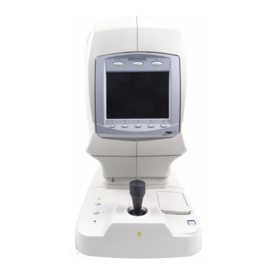
Page 13: Components
COMPONENTS COMPONENT NAMES Main body Section Measuring head Color LCD monitor Control panel Brightness control Measurement switch Control lever Chinrest up/down button Power lamp External I/O terminal Power supply Section Forehead rest Measuring opening Height mark Chinrest tissue stopper pin Chinrest Printer cover open button POWER switch... -
Page 14: Control Panel Components (Ref/Krt Mode)
CONTROL PANEL COMPONENTS (REF/KRT MODE) (1) R/L (2) Mode (3) Print (4) Function button (1) R/L button: Switches between right and left eyes. Sets continuous measurement of both eyes, measurement of the right eye only and measurement of the left eye only. (2) Mode button: Switches between REF/KRT mode and TONO/PACHO mode. - Page 15 PAGE 1 After turning power on, the initial status of PAGE is as follows. (6) Alignment button (8) IOL button (5) Measurement mode button (7) Target image button (9) PAGE selecting button (5) Measurement mode button: Switches between measurement modes of REF/KRT mode. Press- ing the Function button enables you to select R/K (REF/KRT continu- ous measurement), REF (REF measurement) or KRT (KRT measurement).
- Page 16 PAGE 2 PAGE selecting button If the is pressed on PAGE 1, the status of PAGE changes as follows. If the button is pressed again, PAGE 3 is changed. (11) Cornea diameter button (13) R/K menu button (10) Fixation target button (12) Clear button (14) PAGE selecting button (10) Fixation target button:...
-
Page 17: Control Panel Components (Tono/Pacho Mode)
CONTROL PANEL COMPONENTS (TONO/PACHO MODE) (1) R/L (2) Mode (3) Print (4) Function button (1) R/L button: Switches between the right and left eyes. Sets continuous measure- ment of both eyes, measurement of the right eye only and measure- ment of the left eye only. (2) Mode button: Switches between REF/KRT mode and TONO/PACHO mode. - Page 18 PAGE 1 After turning power on, the initial status of PAGE is as follows. (6) Alignment button (8) Safety stop button (5) Measurement mode button (7) Count change button (9) PAGE selecting button (5) Measurement mode button: Switches the measurement modes of the ocular pressure measure- ment and the cornea thickness measurement.
- Page 19 PAGE 2 PAGE selecting button If the is pressed on PAGE 1, the status of PAGE changes as follows. If the button is pressed again, PAGE 3 is returned. (11) 30/60 button (13) T/P menu button (10) Air check button (12) Clear button (14) PAGE selecting button (10) Air check button:...
-
Page 20: Monitor Screen Components (Ref/Krt Mode)
MONITOR SCREEN COMPONENTS (REF/KRT MODE) (1) Mode display (2) Instrument No. (3) Patient No. (4) Right/left eye (16) Selected measuring eye mark (5) REF measurement value (12) Outer alignment mark (6) KRT measurement value (13) Alignment mark (7) Number of REF/KRT measurements (15) Fixation lamp mark (14) IOL mark... - Page 21 (5) REF measurement value: Displays the REF measurement value. Of measurement values, the latest data is displayed on the screen. Figures only: When the measurement was done correct. Figures with *: When the reliability of measurement is low. ERROR: When the measurement was not done correctly. (6) KRT measurement value: Displays the KRT measurement value.
- Page 22 REF mode KRT mode COMPONENTS...
-
Page 23: Monitor Screen Components (Tono/Pacho Mode)
MONITOR SCREEN COMPONENTS (TONO/PACHO MODE) (1) Mode display (2) Instrument No. (3) Patient No. (4) Right/left eye (15) Selected measuring eye mark (5) TONO measurement value (6) TONO average value (11) Alignment mark (7) PACHO measurement value (12) Outer alignment mark (8) Number of TONO/PACHO measurements (10) Number of... - Page 24 (5) TONO measurement value: Displays ocular pressure measurement values. For one eye, three measurement values are displayed on the screen, and thereafter the oldest measurement value is deleted. White figures: When the measurement was done correct. [ ]Yellow figures: When the reliability of measurement is low. ERROR: When the measurement was not done correctly.
- Page 25 TONO mode PACHO mode MEASUREMENT SCREEN UNDER MANUAL MODE (16) Inner alignment mark (16) Inner alignment mark: Used to get alignment in aiming at the patient's eye in manual mode. Change the mark according to the status of alignment. : Alignment is insufficient. : Alignment is sufficient in back/forth, left/right and up/down directions (in the range where measuring is possible).
-
Page 26: Other Screen Displays
OTHER SCREEN DISPLAYS INITIAL SETTING SCREEN (3) Menu end button (1) Set item change button (2) Execution button (1) Set item change button: Move the cursor up/down and select the set item. (2) Execution button: Execute the menu selected by the cursor. (3) Menu end button: Quit the MENU screen and save the set content. - Page 27 CORNEA DIAMETER MEASUREMENT SCREEN (1) Left positioning bar (2) Right positioning bar (3) Move left positioning bar button (5) Initial position button (4) Move right positioning bar button (1) Left positioning bar: Set the left position of cornea diameter measurement. (2) Right positioning bar: Set the right position of cornea diameter measurement.
-
Page 28: Printer Output
PRINTER OUTPUT <R/K> MODE Bar code Instrument No. Work ID No. Instrument No. Patient No. VD (vertex distance) Cylindrical power mark Right eye measure- Measurement Results of 5 right eye measurements ments (recordable up to 10 measurements) Typical value of right eye (The * mark is displayed when 3 or more measurements are done.) SPHERICAL EQUIVALENT of right eye Left eye measurements... - Page 29 When measurement is done under the IOL mode, a reliability factor is printed out following the I mark. The reliability factor is formed with integers 1 to 9 in increasing order of reliability. Additionally, if the reliability is high enough, the reliability factor is not shown in the printout.
- Page 30 <REF> MODE <KRT> MODE Instrument No. Patient No. VD (vertex distance) Cylindrical power mark Typical measured value Results of 5 refractory power mea- surements of right eye (recordable of right eye corneal up to 10 measurements) curvature Typical value of right eye Typical value of right eye SPHERICAL EQUIVALENT Measured value of right...
- Page 31 <T/P> MODE Bar code Instrument No. Work ID No. Instrument No. Measured of intraocular Patient No. pressure values Measured intraocular pressure values Average intraocular pressure values Measured value of central corneal thickness Measured value of central corneal thickness Average value of central corneal thickness Printed example on setting the display unit of intraocular pressure measurement values at hPa.
- Page 32 <TONO> MODE <PACHO> MODE Measured intraocular Measured value of pressure values central corneal thickness Average intraocular Average value of pressure values central corneal thickness Printed example on setting the display unit of intraocular pressure measurement values at hPA on TONO mode. COMPONENTS...
-
Page 33: Standard Accessories
STANDARD ACCESSORIES The following are standard accessories. Make sure that all these items are included (quantity). Power cable (1) Chinrest tissue pin (2) Printer paper (2) Silicon cloth (1) Chinrest tissue (1) Dust cover (1) Fuse (2) Instruction manual, unpacking and assembling (1 each) Accessory case (1) Model eye (1) -
Page 34: Preparations
PREPARATIONS INSTALLING THE INSTRUMENT When moving the instrument, be sure to hold it at the base with two persons. Carrying by one person may cause harm to his back or injury by falling parts. Also, holding areas other than CAUTION the base may cause injury, as well as damage to the instru- ment. -
Page 35: Connecting The Power Cable
CONNECTING THE POWER CABLE To avoid fire and electric shocks by short circuiting, be sure to WARNING connect the instrument into a grounded outlet. To avoid electrical shock, do not handle the power plug with CAUTION wet fingers. Make sure the instrument is OFF. Make sure you can see the mark "O"... -
Page 36: Connecting External I/O Terminals
Connect the cable to the RS232C IN terminal of the instrument. Connect the other cable end to the external device. For inquiries about the RS232C, call your dealer or TOPCON at the address printed on the back cover of this manual. -
Page 37: Function Settings By Means Of Menu
FUNCTION SETTINGS BY MEANS OF MENU LIST OF MENUS MAIN MENU SUB MENU MENU ITEMS SETTING ITEMS Page INITIAL INITIAL BUZZER Setting the buzzer sound SETTING SETTING INIT AUTO Setting the start mode after turning the power on AUTO PRINT Auto print after finishing auto measure- ment PRINT SWITCH... - Page 38 Changing the printout format of date dis- play SERIAL No. PRINT Printing the patient No. INSTRUMENT No. PRINT Printing the instrument No. TOPCON PRINT Printing the TOPCON mark PRINT DATA Setting for printing the measurement result ON-LINE OUTPUT DATA TYPE Selecting the output data format...
-
Page 39: Initial Setting
INITIAL SETTING In the initial setting, patient No., instrument No., refractory power shift, data input/output, printer output, etc. can be set. PREPARATION FOR INITIAL SETTING Make sure the power cable is connected. For connection, see "CONNECTING THE POWER CABLE" on page 34. MENU button POWER switch While pressing the... -
Page 40: Initial Setting
INITIAL SETTING In the INITIAL SET screen, buzzer sound, start mode, patient No., refractory power shift, mon- itor display of typical value, method of corneal diameter measurement, etc. can be changed. In the "INITIAL MENU screen," make sure that the cursor is on "INITIAL SET," and then ENTER press . - Page 41 SETTING THE START MODE AFTER TURNING THE POWER ON The start mode after powering on can be changed. Before shipment, it is set to "AUTO" (auto measurement after powering on). In the "INITIAL MENU screen," select "INITIAL SET" and get the "INITIAL SET screen." Press the Set item change button and bring the cursor to "INIT AUTO."...
- Page 42 SELECTING PRINT BUTTON FUNCTIONS The Print button function can be changed. Before shipment, it is set to "ON" (print). In the "INITIAL MENU screen," select "INITIAL SET" and get the "INITIAL SET screen." Press the Set item change button and bring the cursor to "PRINT SWITCH." Press the Set value change button and select "ON"...
- Page 43 SETTING THE PATIENT No. The patient No. can be set between 0 and 9999. Before shipment, it is set to "0001." In the "INITIAL MENU screen," select " INITIAL SET" and get the " INITIAL MENU screen." Press the Set item change button and bring the cursor to "SERIAL No.
- Page 44 SETTING THE INSTRUMENT No. The instrument No. can be set between 0 and 99. Before shipment, it is set to "01." In the "INITIAL MENU screen," select "INITIAL SET" and get the "INITIAL MENU screen." Press the Set item change button and bring the cursor to "INSTRUMENT No.
- Page 45 SHIFTING THE REFRACTORY POWER The refractory power (S value) can be shifted. Before shipment, it is set to "+0.375." In the "INITIAL MENU screen," select "INITIAL SET" and get the "INITIAL SET" screen. Press the Set item change button and bring the cursor to " DPTR SHIFT." Press the Set value change button to increase the value, or to decrease.
- Page 46 SETTING THE MEASUREMENT MODE AFTER POWERING ON It is possible to set the measurement mode after powering on. Factory setting, it is set to "R/K- T/P" (REF/KRT, TONO/PACHO continuous measurement). Select "INITIAL SET" of the INITIAL MENU screen and get the INITIAL SET screen. Press of the Set item change button and bring the cursor to "...
- Page 47 SETTING THE MEASUREMENT MODE UNDER R/K AND T/P MODE AFTER POWER-ON For both the REF/KRT and TONO/PACHO mode, it is possible to set the measurement mode after powering on. Factory setting, it is set to "INIT" (initial setting state). Select "INITIAL SET" of the INITIAL MENU screen and get the INITIAL SET screen. Press of the Set item change button and bring the cursor to "POWER ON MODE."...
- Page 48 SETTING THE POWER SAVE TIME A time for the power save function can be selected. For shipment, 10min. is set. Select "INITIAL SET" of the INITIAL MENU screen and get the INITIAL SET screen. Press of the Set item change button and bring the cursor to "POWER SAVE TIME." Press the Set value change button and select "OFF", "5", "10", "20", "30", or "60".
- Page 49 Press the Set item change button ; the cursor moves to the next item. The count can be set between 1 and 10. The same count is set for REF and KRT. If different counts are set for TONO and PACHO when the measurement mode is set at T/P, measurement repeats respectively as specified.
-
Page 50: Setting Printout
SETTING PRINTOUT In the PRINT OUT screen, printout format, printing equivalent spherical power, printing com- puter lensmeter data, and printing barcode, sequence of print out, etc. can be changed. In the "INITIAL MENU screen," press and move the cursor to "PRINT OUT." ENTER Press , and the monitor screen is changed to the "PRINT OUT screen."... - Page 51 PRINTING THE CYLINDER SIGN The CYLINDER sign can be printed out. Before shipment it is set to "ON" (print CYLINDER sign). In the "INITIAL MENU screen," select "PRINT OUT" and get the " PRINT OUT" screen. Press the Set item change button and bring the cursor to "CYL PRINT."...
- Page 52 PRINTING THE SPHERICAL EQUIVALENT (S.E. DATA) The SPHERICAL EQUIVALENT can be printed out. Before shipment, it is set to "ON" (print equivalent spherical power). In the "INITIAL MENU screen," select "PRINT OUT" and get the "PRINT OUT screen." Press the Set item change button and bring the cursor to "S.E.
- Page 53 PRINTING PD VALUES PD values can be printed out. Before shipment it is set to "ON" (print PD values). In the "INITIAL MENU screen," select "PRINT OUT" and get the "PRINT OUT screen." Press the Set item change button and bring the cursor to "PD PRINT." Press the Set value change button and select "ON"...
- Page 54 PRINTING THE CREDIBILITY NUMBER The credibility number of measurement data can be printed out. Before shipment, it is set to "OFF" (do not print credibility number). In the "INITIAL MENU screen," select "PRINT OUT" and get the "PRINT OUT screen." Press the Set item change button and bring the cursor to "CREDIBILITY NUM."...
- Page 55 CHANGING THE PRINTOUT FORMAT OF CORNEA MEASUREMENT VALUES The printout format of cornea measurement values can be changed. Before shipment it is set to "ALL" (print all data). In the "INITIAL MENU screen," select "PRINT OUT" and get the "PRINT OUT screen." Press the Set item change button and bring the cursor to "KRT PRINT FORM."...
- Page 56 CHANGING THE PRINTING SEQUENCE KERATOMETRY MEASUREMENT VALUES The sequence of displaying the cornea refractory power and curvature in the printout can be changed. Before shipment, the setting is "D/MM" (print diopter value first) In the "INITIAL MENU screen," select "PRINT OUT" and get the "PRINT OUT screen." Press the Set item change button and bring the cursor to "KRT DATA ORDER."...
- Page 57 CHANGING THE PRINTING SEQUENCE The sequence of display in the printout can be changed. Before shipment, it is set to "DATA" (print REF and KRT values separately). In the "INITIAL MENU screen," select "PRINT OUT" and get the "PRINT OUT screen." Press the Set item change button and bring the cursor to "PRINT R/L."...
- Page 58 When the built-in clock battery is used up, the date is not printed and "DATE" is printed. For questions about the replacement of the built-in battery, call your dealer or TOPCON at the address printed on the back cover of this manual. PREPARATIONS...
- Page 59 CHANGING THE PRINTOUT FORMAT OF DATE DISPLAY The date printout format can be changed. Before shipment it is set to "YMD" (print year/ month/day). In the "INITIAL MENU screen," select "PRINT OUT" and get the "PRINT OUT screen." Press the Set item change button and move the cursor to "DATE/TIME FORM."...
- Page 60 ; the cursor goes to the next item. PRINTING THE TOPCON MARK The TOPCON mark can be printed out. Before shipment it is set to "ON" (print TOPCON mark). In the "INITIAL MENU screen," select "PRINT OUT" and get the "PRINT OUT screen."...
- Page 61 SETTING FOR PRINTING THE MEASUREMENT RESULT It is possible to set the type of printing for the measurement results of the REF/KRT and/or TONO/PACHO mode. Before shipment, it is set to "ALL" (data of both REF/KRT and TONO/ PACHO mode are printed, with a cut between them). Select "PRINT OUT "...
-
Page 62: On-Line Setting (Data Communitation)
ON-LINE SETTING (DATA COMMUNITATION) In the "ON-LINE screen," COMPUTERIZED LENSMETER receiving format, communication format, communication speed and output data can be changed. In the "INITIAL MENU screen," press and move the cursor to "ON-LINE." ENTER Press ; the monitor screen is changed to the "ON-LINE screen." To exit the screen EXIT •... - Page 63 SELECTING THE OUTPUT DATA FORMAT The output data format can be selected. Before shipment, it is set to "REF." In the "INITIAL MENU screen," select "ON-LINE" and get the "ON-LINE screen." Press the Set item change button and bring the cursor to "OUTPUT DATA TYPE." Press the Set value change button and select: (output REF measurement data only),...
- Page 64 SETTING THE COMMUNICATION FORMAT The communication format can be set. Before shipment, it is set as follows by the setting of "OUTPUT DATA TYPE": REF, KRT, R/K: "OLD" (old TOPCON format) TONO, T/P: "MODE1" (average value output format) PACHO, ALL: "STD3"...
- Page 65 Press the Set item change button ; the cursor goes to the next item. For inquiries about the RS-232C communication format, call your dealer or Topcon at the address stated on the back cover. When data is outputted from the USB OUT terminal, either STD1, STD2 or STD3 is taken regardless of setting here.
- Page 66 SELECTING THE OUTPUT PORT The data output port can be selected. Before shipment, it is set to "OFF." In the "INITIAL MENU screen," select "ON-LINE" and get the "ON-LINE screen." Press the Set item change button and bring the cursor to "DATA OUTPUT PORT." Press the Set value change button and select: (do not output data);...
- Page 67 COMPUTERIZED LENSMETER DATA RECEIVING FORMAT The RS-232C receiving format for COMPUTERIZED LENSMETER data can be set. Before shipment, it is set to "NO" (do not receive COMPUTERIZED LENSMETER data). In the "INITIAL MENU screen," select "ON-LINE" and get the "ON-LINE screen." Press the Set item change button and move the cursor to "CL INPUT."...
-
Page 68: Menu Setting
MENU SETTING In menu setting, data step, contact/glasses, continuous measurement, addition number, date and time, as well as the display of cornea shape measurement results and ocular pressure measurement results and the like can be set. PREPARATION FOR MENU SETTING Make sure the power cable is connected. -
Page 69: Returning To The Measurement Screen
RETURNING TO THE MEASUREMENT SCREEN EXIT Press the of the control panel. MENU SCREEN UNDER FULLY AUTOMATIC MEASUREMENT MODE MENU button When the is pressed when the WAITING screen is displayed under AUTO mode for continuously measuring the REF/KRT mode and TONO/PACHO mode, the SET- TING MENU (R/K) screen and SETTING MENU (T/P) screen can be displayed. -
Page 70: Setting Menu (R/K)
The SETTING MENU (R/K) screen or the SETTING MENU (T/P) screen is displayed. To return to the MEASUREMENT screen, press EXIT SETTING MENU (R/K) SETTING CONT. MEAS. (CONTINUOUS MEASUREMENT) Continuous measurement can be set. Before shipment, it is set to "ON" (continuous measure- ment). - Page 71 SETTING THE DATE AND TIME MENU button Press the of the control panel and get the "SETTING MENU (R/K) screen." "CONT. MEAS." is highlighted, and "ON" and "OFF" are displayed on the right. The cursor shows the set content. Press the Set item change button and bring the cursor to "DATE/TIME."...
- Page 72 SETTING STEP The measurement step can be selected from 0.12 and 0.25. Before shipment, it is set to "0.25." MENU button Press the of the control panel and get the "SETTING MENU (R/K) screen." "CONT. MEAS." is highlighted, and "ON" and "OFF" are displayed on the right. The cursor shows the set content.
- Page 73 SETTING AXIS STEP ° ° ° The axial angle step can be selected from 1 or 5 . Before shipment, it is set to "1 ." MENU button Press the of the control panel and get the "SETTING MENU (R/K) screen."...
- Page 74 SETTING VD In vertex distance (VD) setting, contact lens (0) or glasses (12mm or 13.75mm) can be selected. Before shipment, it is set to glasses (12mm). MENU button Press the of the control panel and get the "SETTING MENU (R/K) screen."...
- Page 75 SETTING THE ADDITION NUMBER By selecting an age, the general addition number for the age can be selected. Before ship- ment, it is set to "NO" (unset). MENU button Press the of the control panel and get the "SETTING MENU (R/K) screen."...
- Page 76 SETTING D/mm The unit of kerato measurement result displayed on the monitor screen can be selected from D (refractory power) or mm (curvature). Before shipment, it is set to "mm" (curvature). MENU button Press the of control panel and get the "SETTING MENU (R/K) screen." "CONT.
- Page 77 SETTING HV/R1R2 The display format of kerato measurement result displayed on the monitor screen can be selected from HV (horizontal/vertical) or R1R2 (major/minor meridian). Before shipment, it is set to "HV" (horizontal/vertical). MENU button Press the of control panel and get the "SETTING MENU (R/K) screen." "CONT.
- Page 78 SETTING CYL SIGN The display format of CYLINDER sign on the monitor screen can be selected from "-," "+" and "MIX." Before shipment, it is set to "-." MENU button Press the of control panel and get the "SETTING MENU (R/K) screen." "CONT.
- Page 79 SETTING THE MEASUREMENT MODE UNDER REF/KRT MODE It is possible to set the measurement mode under the REF/KRT mode after power-on. Factory setting, it is set to "R/K" (REF/KRT measurement mode). MENU button Press the of the control panel and get the SETTING MENU(R/K) screen.
- Page 80 SETTING MESSAGE INPUT You can add a brief message to the printout. MENU button Press the of control panel and get the "SETTING MENU (R/K) screen." "CONT. MEAS." is highlighted, and "ON" and "OFF" are displayed on the right. Press the Set item change button and bring the cursor to "MESSAGE INPUT."...
- Page 81 ENTER With the cursor on the inputted character, press Input the message by repeating steps 4 and 5. EXIT When the input operation is finished, press Press the Set item change button ; the cursor moves to the previous item (INITIAL MODE).
-
Page 82: Seeting Menu (T/P)
SEETING MENU (T/P) SETTING THE DATE AND TIME MENU button Press the of the control panel and get the "SETTING MENU (T/P) screen." "DATE/TIME" is highlighted, and date/time is displayed on the right. The cursor shows the set content. MEASUREMENT switch Press the and highlight the desired item. - Page 83 SETTING THE AVERAGE VALUE OF OCULAR PRESSURE MEASUREMENTS The display format of average value of ocular pressure measurements displayed on the moni- tor screen can be selected from INT (integer) or REAL (to tenth). Before shipment, it is set to "INT"...
- Page 84 SETTING THE MEASUREMENT MODE UNDER TONO/PACHO MODE It is possible to set the measurement mode under the TONO/PACHO mode after power-on. Factory setting, it is set to "ocular pressure" (TONO measurement mode). MENU button Press the of the control panel and get the "SETTING MENU (T/P) screen."...
- Page 85 SETTING MESSAGE INPUT You can add a brief message to the printout. MENU button Press the of control panel and get the "SETTING MENU (T/P) screen." "DATE/TIME" is highlighted, and date/time is displayed on the right. Press the Set item change button and bring the cursor to "MESSAGE INPUT."...
- Page 86 ENTER With the cursor on the inputted character, press Input the message by repeating steps 4 and 5. EXIT When the input operation is finished, press Press the Set item change button ; the cursor moves to the previous item (INITIAL MODE).
-
Page 87: Setting The Printer Paper
SETTING THE PRINTER PAPER To avoid potential injury, do not touch the printer body while the CAUTION printer is in operation or when replacing the printer paper. To avoid failure or potential injury, do not open the printer cover CAUTION while the printer is in operation. - Page 88 Set the paper into the shaft support, taking care of the roll direction of paper. Pull out the paper top 2 to 3cm forward. Roll direction Roll direction Pull the paper along the paper guide and draw it out straightly from the cover. Paper guide Close the printer cover as if to press the drawn-out paper.
-
Page 89: Resetting From Power Save Status
RESETTING FROM POWER SAVE STATUS This instrument uses a power save system for saving electric power. When the main body is not in operation for approximately 10 minutes, power supply to the monitor is stopped. Under the power save condition, only the POWER lamp of control panel lights and the monitor screen is off. - Page 90 Vertical movement When the control lever is rotated, the measuring head moves up and down. Turning the lever clockwise will raise the measuring head and turning counterclockwise lowers it. Measurement operation Pressing the Measurement switch at the top of the control lever will start measurement. During the AUTO measurement, continuously pressing the Measurement switch will effect the following movements: REF/KRT measurement:...
-
Page 91: Basic Operations
BASIC OPERATIONS CHANGING THE MEASUREMENT MODE MEASUREMENT MODE To avoid injury in changing the measurement mode, do not CAUTION place fingers into the measuring opening. * Inform the patient accordingly MODE button Select the desired measurement mode by pressing the of the control panel. - Page 92 MODE button Press the to go to the next screen. MODE button When the screen is displayed, press the and select the desired mea- surement mode. PRINT button After selecting the measurement mode, press the and finish setting. In the initial setting the REF/KRT TONO/PACHO is set, but this can be changed.
-
Page 93: Type Of Measurement To Be Done Under Ref/Krt Measurement Mode
TYPE OF MEASUREMENT TO BE DONE UNDER REF/KRT MEASUREMENT MODE Select the type of measurement to be done under the REF/KRT mode. In the REF/KRT measurement mode screen, press the MEASUREMENT MODE button of function button on the control panel and select the desired type of measurement. -
Page 94: Type Of Measurement To Be Done Under Tono/Pacho Measurement Mode
TYPE OF MEASUREMENT TO BE DONE UNDER TONO/PACHO MEASURE- MENT MODE Select the type of measurement to be done under the TONO/PACHO mode. In the TONO/PACHO measurement mode screen, press the MEASUREMENT MODE button of the control panel and select the desired type of measurement. -
Page 95: Choosing The Eye To Be Measured
CHOOSING THE EYE TO BE MEASURED R/L button Choose the eye to be measured. Press the of the control panel. Both eyes are measured continuously (Both eye measurement mode) Only the right eye is measured. (Right eye measurement mode) If the main body is positioned for measuring the left eye, it moves to the position for measuring the right eye by choosing Only the left eye is measured. - Page 96 R/L button When the screen is displayed, press the and choose the measurement mode. 0002 0002 R/L SELECT R/L SELECT Select Select R 00 R 00 Select the operation. Select the operation. K 00 K 00 [–] 12.00 [–] 12.00 AUTO AUTO 0002...
-
Page 97: When Measuring The Refractory Power And Corneal Curvature Radius Of The Eye
WHEN MEASURING THE REFRACTORY POWER AND CORNEAL CURVA- TURE RADIUS OF THE EYE To avoid injury in changing the measurement mode, do not CAUTION place fingers into the measuring opening. * Inform the patient accordingly The measurement in auto mode may be impossible due to the eyelid and the eyelashes over to the pupil. - Page 98 If the MEASUREMENT screen is displayed, the message "CHECK EYE LEVEL AND FOREHEAD, PRESS MEASURE SW" is shown. At this time, alignment operation is unavailable even if the alignment mode has been set to AUTO. MEASUREMENT switch Press following the message given, and normal mea- surement screen is gained.
-
Page 99: Positioning The Patient
If the chinrest does not work even when the button or button is pressed (a POWER switch failure), turn off the , pull off the power cable, and call your dealer or TOPCON at the address printed on the back cover of this manual. BASIC OPERATIONS... -
Page 100: Adjusting Monitor's Angle
ADJUSTING MONITOR'S ANGLE Adjust the monitor's angle to a comfortable viewing position either standing or siting. BASIC OPERATIONS... -
Page 101: Measurement Under Auto Mode (Ref/Krt Mode)
MEASUREMENT UNDER AUTO MODE (REF/KRT MODE) Adjust the height of the automatic instrument table so that the patient MEMO can sit on the chair comfortably and correct measurement values can be obtained. SETTING THE AUTO MODE In the initial status after power on, the mode is set to auto mode (AUTO). Make sure the MEASUREMENT screen is on. - Page 102 ALIGNMENT AND MEASUREMENT Before starting measurement, be sure to confirm the measur- ing screen (to avoid making the ocular pressure measurement CAUTION to the patient's eye wearing a contact lens.) If measurement is not possible under auto mode (this may occur when MEMO the cornea condition is not good enough), perform the measurement using manual mode.
- Page 103 Hold the control lever and move the main body to the operator side. Operate the control lever laterally and vertically and get the patient's eye in the center of the color LCD monitor screen. While moving the main body toward the patient, focus on the patient's eye. A vague refer- ence dot for alignment appears reflected on the cornea.
- Page 104 Then auto alignment starts, and alignment and measurement is done automatically. After the measurement is finished, the measurement result is displayed on the color LCD monitor screen. If the limit icon " " appears during auto alignment, indicating that the main body has reached the limit of movement, manually operate the unit toward the direction of align- ment.
- Page 105 If returning to another eye measuring position is complete, alignment operation starts and the measurement is carried out automatically. If the measurement completes, the result is shown on the color LCD monitor screen. In fully automatic measurement mode (REF/KRT and TONO/PACHO modes), after REF/ KET measurement, the measurement mode is changed to TONO/PACHO automatically.
-
Page 106: Measurement Under Manual Mode (Ref/Krt Mode)
MEASUREMENT UNDER MANUAL MODE (REF/KRT MODE) Adjust the height of the automatic instrument table so that the patient MEMO can sit on the chair comfortably and correct measurement values can be obtained. SETTING THE MANUAL MODE In the initial status after power on, the mode is set to auto mode (AUTO). Make sure the MEASUREMENT screen is on. - Page 107 ALIGNMENT AND MEASUREMENT Before starting measurement, be sure to confirm the measur- ing screen (to avoid making the ocular pressure measurement CAUTION to the patient's eye wearing a contact lens.) Alignment operations are done by the control lever. For operating the main body by the control lever, see "ALIGNMENT AND MEA- SUREMENT"...
-
Page 108: Displaying Measurement Values (Ref/Krt Mode)
When the luminous point becomes the smallest and enters the alignment mark, press the MEASUREMENT switch Even when alignment is not correct, measurement is done by pressing the MEASUREMENT switch . To ensure accurate measurement results, surely obtain correct alignment before starting measurement. Measurement is done and measurement values are displayed. -
Page 109: Deleting Measurement Values (Ref/Krt Mode)
DELETING MEASUREMENT VALUES (REF/KRT MODE) PAGE selecting button Press the of the control panel. PAGE 2 is displayed. PAGE selecting button CLEAR button Press the of the control panel until the buzzer sounds" Pi!". CLEAR button All measurement values, both right and left eyes are cleared, and the system returns to the initial status after power on. -
Page 110: When Measuring The Ocular Pressure And Cornea Thickness Of The Eye
WHEN MEASURING THE OCULAR PRESSURE AND CORNEA THICKNESS OF THE EYE To avoid injury in changing the measurement mode, do not CAUTION place fingers into the measuring opening. * Inform the patient accordingly The measurement in auto mode may be impossible due to the eyelid and the eyelashes over to the pupil. -
Page 111: Checking The Measuring Nozzle
CHECKING THE MEASURING NOZZLE Before measuring, check if there is any foreign matter on and around the measuring nozzle. CAUTION If any, it may enter and damage the patient's eye during the measurement. Remove the measuring window lens cap. Measuring window lens cap Check if there is any foreign matter on and around the measuring nozzle. -
Page 112: Air Check
AIR CHECK This instrument is equipped with a function for checking correct operations of the measure- ment system inside the instrument. PAGE selecting button In the TONO/PACHO mode measurement screen, press the PAGE selecting button Air check button is displayed in the function menu display. Air check button Check if there is any object before the measuring nozzle, and press the Air check button... - Page 113 POWER switch If there is no object, a failure is suspected. Turn the to OFF, unplug the power cable, and call your dealer or TOPCON at the address printed on the back cover of this manual. Abnormal operation screen PAGE selecting button...
-
Page 114: Positioning The Patient
If the chinrest does not work even when the button or button is pressed (a POWER switch failure), turn off the , pull off the power cable, and call your dealer or TOPCON at the address printed on the back cover of this manual. BASIC OPERATIONS... -
Page 115: Adjusting Monitor's Angle
ADJUSTING MONITOR'S ANGLE Adjust the monitor's angle to a comfortable viewing position either standing or siting. SETTING THE SAFETY STOP Before measuring, set the safety stop to prevent the measuring CAUTION window glass from hitting the patient's eye. Set it respectively for the right and left eyes. Set the safety stop from the side face of the instrument. - Page 116 Safety stop button Press the and open the SAFETY STOP SETTING screen. The dis- Safety stop button play of is highlighted. Safety stop button When it enters into setting mode, the below-mentioned message is indicated in alter- nately. Hold the control lever and pull the main body fully toward the patient side. Turn the control lever and bring the measuring nozzle to a height of the cornea center of the patient's eye.
- Page 117 When the measuring nozzle reaches a position 8-9mm from the cornea, press the MEASUREMENT switch . This sets the safety stop position and returns the highlighted Safety stop button to the normal display condition. 8-9mm Safety stop button Safety stop button When the is highlighted, pressing the again will cancel the position setting and returns to the previously set position.
-
Page 118: Measurement Under Auto Mode (Tono/Pacho Mode)
MEASUREMENT UNDER AUTO MODE (TONO/PACHO MODE) Adjust the height of the automatic instrument table so that the patient MEMO can sit on the chair comfortably and correct measurement values can be obtained. SETTING THE AUTO MODE In the initial status after power on, the mode is set to auto mode (AUTO). Make sure the Measurement screen is on. - Page 119 SETTING THE MEASUREMENT MODE This instrument can select the measurement mode from T/P (ocular pressure/cornea thick- ness continuous measurement), TONO (ocular pressure measurement) and PACHO (cornea thickness measurement). Make sure the MEASUREMENT screen is on. MEASUREMENT MODE button Press the of the control panel and select the mea- surement mode.
- Page 120 30/60 button Press the of the control panel and set the measuring range. 30/60 button ALIGNMENT AND MEASUREMENT Before starting measurement, be sure to confirm the measur- ing screen (to avoid making the ocular pressure measurement CAUTION to the patient's eye wearing a contact lens.) It is recommended that you do ocular pressure measurements several times.
- Page 121 Hold the control lever and move the main body to the operator side. Operate the main body laterally and vertically the control lever and get the patient's eye in the center of the color LCD monitor screen. Tell the patient to gaze at the yellow-green light. Move the main body to the patient side slightly.
- Page 122 As reference dot for alignment appears, auto alignment operation begins so to maintain the reference dot. When the main body approaches the patient's eye, the alignment bar and FORWARD are displayed on the color LCD monitor screen. Alignment bar To ensure correct measurements, take care so that the eyelash and eyelid do not enter the outer alignment mark.
- Page 123 After the alignment bar is displayed, move the main body to the patient side only a little. Auto alignment starts, and alignment and measurement is done automatically. After the measurement is finished, the measurement result is displayed on the color LCD monitor screen.
- Page 124 If returning to another eye measuring position is complete, alignment operation starts and the measurement is carried out automatically. If the measurement completes, the result is shown on the color LCD monitor screen. If the limit icon " " appears during auto alignment, indicating that the main body has reached the limit of movement, manually operate the unit toward the direction of align- ment.
-
Page 125: Measurement Under Manual Mode (Tono/Pacho Mode)
MEASUREMENT UNDER MANUAL MODE (TONO/PACHO MODE) Adjust the height of the automatic instrument table so that the patient MEMO can sit on the chair comfortably and correct measurement values can be obtained. SETTING THE MANUAL MODE In the initial status after power on, the mode is set to auto mode (AUTO). Make sure the MEASUREMENT screen is on. - Page 126 SETTING THE MEASURING RANGE In this instrument, the measuring range can be switched in 2 steps between 0-30 and 0-60. Normally, "0-30" is used, but if the patient's ocular pressure is high, switch it to 0-60. The initial status after power on of the measuring range is "0-30." Make sure the MEASUREMENT screen is on.
- Page 127 ALIGNMENT AND MEASUREMENT Before starting measurement, be sure to confirm the measur- ing screen (to avoid making the ocular pressure measurement CAUTION to the patient's eye wearing a contact lens.) It is recommended measure the ocular pressure several times. Since the MEMO ocular pressure varies by heart beats and tears, often it is not possible to obtain exact measurement values by measuring only once or twice.
- Page 128 Move the main body to the patient side slightly. As the instrument comes in the range where ocular pressure measurement is possible, the focus is switched and the outer alignment mark displays. While moving the main body further toward the patient, focus on the patient's eye. A vague reference dot for alignment appears reflected on the cornea.
- Page 129 If the main body is too close to the patient's eye, relative to the alignment position, TOO CLOSE, or if it is too far, FORWARD, are displayed on the color LCD monitor screen. The alignment bar is displayed with a broken line when the instrument is near the patient's eye, and with a solid line when it is apart.
- Page 130 MEASUREMENT switch Under the aligned condition, press the Air is ejected and measurement is done, and the measurement value is displayed. Even when alignment is not correct, measurement is done by pressing the MEASUREMENT switch . To ensure accurate measurement results, make sure to obtain correct alignment before starting.
-
Page 131: Measuring The Cornea Thickness (Tono/Pacho Mode)
MEASURING THE CORNEA THICKNESS (TONO/PACHO MODE) Adjust the height of the automatic instrument table so that the patient MEMO can sit on the chair comfortably and correct measurement values can be obtained. SETTING THE MEASUREMENT MODE This instrument can select the measurement mode from T/P (ocular pressure/cornea thick- ness continuous measurement), TONO (ocular pressure measurement) and PACHO (cornea thickness measurement). -
Page 132: Displaying Measurement Values (Tono/Pacho Mode)
DISPLAYING MEASUREMENT VALUES (TONO/PACHO MODE) For one eye, three measurement values are displayed on the screen, and thereafter the oldest measurement value is deleted. White figures: When the measurement was done correct. For changing the display unit, see "SETTING THE DISPLAY UNIT OF OCULAR PRESSURE MEASUREMENT VALUES"... -
Page 133: Deleting Measurement Values (Tono/Pacho Mode)
DELETING MEASUREMENT VALUES (TONO/PACHO MODE) PAGE selecting button Press the of the control panel. PAGE 2 is displayed. PAGE selecting button CLEAR button Press the of the control panel. All measurement values, both right and left eyes are cleared, and the system returns to the initial status after power on. -
Page 134: In A Case Like This
IN A CASE LIKE THIS TO STOP MEASUREMENT MODE button Stop the measurement by pressing the MODE button You can stop the measurement in the middle by pressing the during the measurement operation. MODE button When the is pressed during the auto measurement of REF/KRT mode, or during the auto measurement of TONO/PACHO mode, the buzzer rings 3 times and the waiting screen of each mode is given. -
Page 135: To Measure The Right/Left Eye Only
Stop the measurement by operating the control lever Tilt the control lever and pull to the operator side. The main body retreats. To resume the measurement operation, tilt the control lever to the patient side, and bring the main body slowly into focus on the patient eye. In the auto measurement, the measurement operation starts automatically when the focus is reached. - Page 136 When the continuous REF/KRT TONO/PACHO mode is set, first the REF/KRT measure- ment is done, followed by the TONO/PACHO measurement. When "R" is selected while the main body is at the position for measuring the left eye, the main body moves automatically to the position for measuring the right eye.
-
Page 137: The Limit Icon Appears And The Measurement Is Not Possible
THE LIMIT ICON APPEARS AND THE MEASUREMENT IS NOT POSSIBLE When the main body moves to the other eye after measuring one eye, sometimes the limit icon appears and the measurement is not possible. In this case, often the patient's face leans to the right or left side. -
Page 138: The Nozzle Limit Appears And The Measurement Is Not Possible
THE NOZZLE LIMIT APPEARS AND THE MEASUREMENT IS NOT POSSIBLE If the nozzle limit appears and the measurement is disabled under TONO/PACHO mode, check the position of the patient's face. If the patient's face is put on the chinrest, with the forehead stopped correctly at the fore- head rest, set again safety stop. -
Page 139: Alignment Does Not Start
MEASUREMENT switch Press the and set the safety stop. ALIGNMENT DOES NOT START The measurement in auto mode may be impossible due to the eyelid and the eyelashes over to the pupil. MEMO For this case, an operator tells the patient to open eyes enough, or lifts the eyelid while taking care so as to press the patient's eye. - Page 140 MEASUREMENT switch Press the and start the measurement. THE IMAGE OF THE PATIENT'S EYE DISPLAYED ON THE MONITOR IS NOT CLEAR Check if the patient's forehead is pressed against the forehead rest. If not, move the fore- head forward. If the patient's eye and the main body are not aligned, tilt the control lever to the patient side, move the main body slowly toward the patient's eye and get it focused.
- Page 141 THE PATIENT'S EYE IS WIDELY OFF THE SCREEN CENTER If the patient's eye is off the screen center too much, alignment is not done or the align- ment operation takes long. Tilt the control lever and bring the patient's eye closer to the screen center. If the patient's eye leans to the left side of the color LCD monitor screen, for example, tilt the control lever to the left.
-
Page 142: Individual Operations
INDIVIDUAL OPERATIONS CHANGING THE NUMBER OF MEASUREMENTS MEASUREMENT COUNT SETTING BY INITIAL SETTING Under auto mode, the number of measurements of REF/KRT, TONO and PACHO can be changed respectively. From factory the set count and setting range are as follows: Initially set count (measurements) Setting range (measurements) REF/KRT... -
Page 143: Displaying All Measurement Data
DISPLAYING ALL MEASUREMENT DATA The latest data are displayed as measurement values, but it is possible to confirm all the data measured. Measurement data can be selected and displayed from "REF data," "KRT data" and "ocular pressure/cornea thickness data." PAGE selecting button Under KRT mode, press the of the control panel. - Page 144 If there is no measurement data, the display is blank. Under T/P mode, "ocular pressure/cornea thickness data" is displayed first. R/L button When the of the control panel is pressed, REF left eye data is displayed, and when the switch is pressed again, REF right eye data is returned. KRT button When the of the control panel is pressed, KRT data is displayed.
- Page 145 If data include three measurements only, 1st and 2nd data are returned after dis- playing 3rd data. REF button When the of the control panel is pressed, the screen displays REF T/P button data, and when the is pressed, the screen displays ocular pressure/ cornea thickness data.
- Page 146 EXIT To exit the data display and return to the Measurement screen, press of the con- trol panel. EXIT button INDIVIDUAL OPERATIONS...
-
Page 147: Printing Measurement Values
PRINTING MEASUREMENT VALUES • To avoid paper jam in the printer, do not feed the paper if it is partly cut/torn or wrinkled. • To avoid discoloring the printing paper (particularly the recording area) during storage, use a polypropylene holder and not one containing plasticizer (PVC, etc.). - Page 148 If "CLOSE PRINTER COVER" is displayed, close the printer cover till it clicks, and PRINT button then press the again. The "ERROR" mark is not printed. Also, printing is not done if there is no measure- ment value. When a red line appears at the end of the printer paper, replace it with a new one.
-
Page 149: Measuring The Cornea Diameter
MEASURING THE CORNEA DIAMETER For measuring the cornea diameter, "ON" (measuring static image) or "OFF" (measuring actual image) can be selected at C.D MEMORY in the initial setting. To change the setting, see "CHANGING THE METHOD OF CORNEA DIAMETER MEA- SUREMENT"... - Page 150 Press the MOVE LEFT POSITIONING BAR button (move to the left) or (move to the right) and bring the left positioning bar to the left end of iris. MOVE LEFT POSITIONING BAR button Press the MOVE RIGHT POSITIONING BAR button (move to the left) or (move to the right) and bring the right positioning bar to the right end of iris.
- Page 151 MEASUREMENT switch Press the and display the change right/left message. Press the R/L button and make the mode for measuring the left eye. Measure the left eye in like manner. MEASUREMENT switch After data for both eye are displayed, press the and return to the MEASUREMENT screen.
- Page 152 MEASURING THE STATIC IMAGE CORNEA DIAMETER button Press the Focus on the patient's eye. When saving the image of the right eye, for example, first aim at the right eye. Make sure the CORNEA MEMORY screen is on. MEASUREMENT switch Press the .
- Page 153 MEASUREMENT switch To do image saving again, press the R/L button The change right/left message is displayed. Press the and move the mea- suring head to the left eye. Save the image of the left eye in like manner. If you want to save again the image of the right eye after moving to the left eye, R/L button press the to move to the right eye, and then press the...
- Page 154 Make sure the CORNEA DIAMETER screen is on. Press the MOVE LEFT POSITIONING BAR button (move to the left) or (move to the right) and bring the left positioning bar to the left end of iris. Press the MOVE RIGHT POSITIONING BAR button (move to the left) or (move to the right) and bring the right positioning bar to the right end of iris.
-
Page 155: Measuring The Hard Contact Lens
MEASURING THE HARD CONTACT LENS Make sure of kerato measurement (R/K mode or KRT mode). If not, choose kerato mea- MEASUREMENT MODE button surement (R/K mode or KRT mode) by the Fill the recessed part of the contact lens holder with water, and place the contact lens there. -
Page 156: Input/Output Using Rs-232C
INPUT/OUTPUT USING RS-232C OUTPUT USING RS-232C This instrument can output data to PC and the like via the RS-232C interface. Make sure that the connection is to the RS-232C OUT. For connection, see "CONNECTING EXTERNAL I/O TERMINALS" on page 35. Check settings for data communication. -
Page 157: Maintenance And Checking
MAINTENANCE AND CHECKING DAILY MEAINTENANCE CHECKING THE MEASURING ACCURACY Measure the attached model eye and check the accuracy at regular intervals. Keep this instrument free of dust. When not in use, put the measuring lens cap and dust cover on. POWER switch When not in use, turn off the CLEANING THE INSTRUMENT... -
Page 158: Cleaning The Nozzle And Chamber Glass Inside The Measuring Nozzle
Wipe the glass surface lightly with the applicator, from the center outward. Wiping the glass surface Use a new applicator and wipe the glass surface repeatedly several times. Repeat the cleaning operation several times, using a new applicator each time, till oil spots are removed from the window glass. -
Page 159: Adjusting The Monitor Screen
Insert the applicator into the nozzle, lightly touch the glass surface, and turn the applicator a few times. Applicator (attached) Use a new applicator and wipe the glass surface in a similar manner; repeat this a few times. The used applicator contains grease and it only scatters grease if used again; the light transmittance is not improved at all. -
Page 160: Printer Paper Jam
PRINTER PAPER JAM To avoid potential injury, do not touch the printer body while the CAUTION printer is in operation or when replacing the printer paper. To avoid failure or potential injury, do not open the printer cover CAUTION while the printer is in operation. To avoid potential injury in case of malfunction, including a CAUTION paper jam, be sure to shut off the power before attempting to... -
Page 161: Replacing The Fuse
REPLACING THE FUSE When changing the fuse, turn off the power, and disconnect WARNING the power cord. Use the rated fuse. Make sure the power is OFF and the power cable is unplugged. Press the fuse holder with a screwdriver and turn it counterclockwise. The fuse holder can be taken out. -
Page 162: Special Note Of Cleaning
SPECIAL NOTE OF CLEANING CLEANING THE OUTER COVER AND MONITOR SCREEN Do not use or apply any spray-type cleaner near the instru- ment. CAUTION If the cleaner remains inside the measuring nozzle, the patient's eye may be injured during measurement. •... -
Page 163: Before Requesting Service
AIR CHECK If a problem is suspected, do the air check. If the result is "NG[+]" or "NG[-]," call your dealer or TOPCON at the address printed on the back cover of this manual. For details about the air check, see "AIR CHECK" on page 111. -
Page 164: Message List
REFERENCES MESSAGE LIST "OVER-SPH" Spherical power exceeds +22D or -25D (at VD=12mm). "OVER-CYL" Cylindrical power exceeds ±8D (at VD=12mm). "OVER-R" Corneal curvature exceeds 5.00-10.00mm. "NO TARGET" No patient's eye or the eye image is too dark. "AGAIN" A difference of more than 5D from the value of previous measure- ment "NO CENTER"... -
Page 165: Optional Accessories
OPTIONAL ACCESSORIES Automatic instrument table AIT-16 Because the instrument height can be adjusted to the desired position, you can take a picture more easily. Specification • Dimensions ....525(W)x490(D)mm • Table height....600 - 880mm • Table size ....490 x 500mm • Weight ......Approx. 23kg (only the instrument body) •... -
Page 166: Ordering Consumable Supplies
ORDERING CONSUMABLE SUPPLIES When ordering consumable supplies, tell your dealer the product name, part No. and the nec- essary quantity. Product name Part No. Chinrest tissue 40310 4082 Silicone cloth 31087 2007 Dust cover 42360 9002 Applicator 41601 8606 Printer paper 44800 4001 Fuse 3A 250V T2400 0158A... - Page 167 MARKS DISPLAYED OUTSIDE THE MAIN BODY Symbol IEC Publication Description Description (French) 60417-5032 Alternating Current Courant alternatif Attention, consult accompa- Attention, consulter les docu- 60348 nying documents ments d'accompagnement (power: disconnection Eteint (courant: coupure 60417-5008 from the main power supply) avec le secteur) On (power: connection to the Allume (courant: raccorde-...
-
Page 168: Rs232C Communication Specifications
RS232C COMMUNICATION SPECIFICATIONS CONNECTOR TYPE DSUB 9-pin (EIA RS232C) DE-9S-N (JAE) INPUT TERMINAL PIN ARRANGEMENT 9pin-9pin connection TRK-1P side Transmission/ Code Description Receiving side RD (RXD) Data receiving SD (TXD) Data transmission ER (DTR) Data terminal ready SG (GND) Signal grounding... -
Page 169: Specifications
SPECIFICATIONS SPECIFICATION AND PERFORMANCE REF measurement Measuring range Hyperopia: 0 to +22D 0.25D step display (switchable to 0.12D step display) Myopia: 0 to -25D 0.25D step display (switchable to 0.12D step display) Astigmatism: 0 to 10D (+ or -) 0.25D step display (switchable to 0.12D step display) °... -
Page 170: Dimensions And Weight
DIMENSIONS AND WEIGHT Dimensions: 304(W)x521(D)x551-581(H)mm Weight: 27.0kg INTENDED USE Measurement of spherical refractory power, cylindrical refractory power, astigmatic axial direction, corneal curvature, meridian direction, corneal refractory power, ocular pressure and cornea thick- ness. OPERATION PRINCIPLES REF measurement: Measurement of spherical refractory power, cylindrical power and astigmatic axial direction is computing based on the reflected image, which is received by the CCD camera, of the luminous flux for refractory measurement (near-infrared light) projected to the retina. -
Page 171: Electromagnetic Compatibility
Guidance and manufacturer's declaration - electromagnetic emissions The TRK-1P is intended for use in the electromagnetic environment specified below. The customer or the user of the TRK-1P should assure that it is used in such an environment. Emissions test Compliance... - Page 172 Guidance and manufacturer's declaration - electromagnetic immunity The TRK-1P is intended for use in the electromagnetic environment specified below. The customer or the user of the TRK-1P should assure that it is used in such an environment. Immunity test IEC 60601...
- Page 173 Guidance and manufacturer's declaration - electromagnetic immunity The TRK-1P is intended for use in the electromagnetic environment specified below. The customer or the user of the TRK-1P should assure that it is used in such an environment. Immunity test IEC 60601...
- Page 174 Recommended separation distance between portable and mobile RF communications equipment and the TRK-1P The TRK-1P is intended for use in an electromagnetic environment in which radiated RF distur- bances are controlled. The customer or the user of the TRK-1P can help prevent electromag-...
-
Page 175: Equipment Classification
EQUIPMENT CLASSIFICATION • Type of protection against electric shocks: Class The Class equipment provides means to connect itself to the protective grounding system of utilities to thereby independently provide protection against electric shocks by keeping con- nectable metal components nonconductive in case of a failure in the basic insulation. •... - Page 176 When calling please give us the following information about your unit: • Instrument type: TRK-1P • Manufacturing No. (Shown on the rating plate on the back of the instrument) • Period of Usage (Please give us the date of purchase.) •...
- Page 177 AUTO KERATO-REFRACTO-TONOMETER TRK-1P 41850 95990 Printed in Japan 2008.04-100LW0...
Need help?
Do you have a question about the TRK-1P and is the answer not in the manual?
Questions and answers