Table of Contents
Advertisement
Quick Links
Advertisement
Table of Contents

Related Manuals for Topcon TRC-NW400


Summary of Contents for Topcon TRC-NW400
- Page 1 USER MANUAL NON-MYDRIATIC RETINAL CAMERA TRC-NW400...
-
Page 3: Introduction
Microsoft and Windows are the registered trademarks of Microsoft Corporation in U.S. IPA font is used in some parts for TRC-NW400. Any and all terms and conditions of "IPA Font License Agreement v1.0" shall be deemed to be accepted and agreed by you if you use TRC-NW400. - Page 4 3. The contents of this manual are correct to the best of our knowledge. Please inform us of any ambiguous or erroneous descriptions, missing information, etc. 4. Original Instructions This instruction manual was originally written in English. ©2014 TOPCON CORPORATION ALL RIGHTS RESERVED...
-
Page 5: Table Of Contents
CONTENTS INTRODUCTION ......................... 1 GENERAL SAFETY INFORMATION ..................5 HOW TO USE THIS MANUAL ....................7 GENERAL MAINTENANCE INFORMATION ..............7 DISCLAIMERS ..........................7 DISPLAYS AND SYMBOLS FOR SAFE USE ..............8 POSITIONS OF WARNING AND CAUTION INDICATIONS .......... 9 SYSTEM DIAGRAM .......................... - Page 6 CLEANING ............................. 94 OPTIONAL ACCESSORIES ......................96 EXTERNAL FIXATION TARGET EF-2 ..................96 REFERENCE MATERIAL ........................ 97 TYPE OF PLUG ..........................97 RELATION BETWEEN THE SETTING OF THE ILLUMINATION/FLASH LEVEL AND MAXIMUM RADIANCE ........................98 TRC-NW400 SOFTWARE LICENSE TERMS ................99...
-
Page 7: General Safety Information
GENERAL SAFETY INFORMATION CONTRAINDICATIONS This instrument must not be used for the following patients: • Patients who are hypersensitive to light. • Patients who recently underwent photodynamic therapy (PDT). • Patients taking medication that causes photosensitivity. WARNINGS Ensuring the Safety of Patients and Operators Be careful not to hit the patient's eyes or nose with the instrument during operation. - Page 8 To avoid electric shock, do not open the instrument. Request service from an authorized Topcon distributor. Preventing Electric Shock and Burn To avoid fire and electric shock, install the instrument in a place free of water and other liquids.
-
Page 9: How To Use This Manual
When the customer has obtained data through this software and has saved or backed up the data in a server or personal computer, TOPCON shall not take any responsibility for the loss of the data, loss of profit or other damages on the customer. -
Page 10: Displays And Symbols For Safe Use
DISPLAYS AND SYMBOLS FOR SAFE USE To encourage safe and proper use and to prevent injury to the operator and others or potential damage to property, important messages are put on the instrument body and inserted in the instruction manual. We suggest that everyone understand the meaning of the following displays, icons and text before read- ing the "GENERAL SAFETY INFORMATION"... -
Page 11: Positions Of Warning And Caution Indications
POSITIONS OF WARNING AND CAUTION INDICATIONS To ensure safety, this machine provides warning displays. Use the instrument correctly by observing the display instructions. If any of the following display labels are missing, contact your TOPCON dealer at the address listed on the back cover. -
Page 12: System Diagram
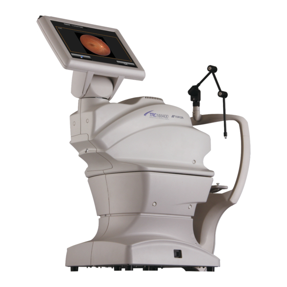
SYSTEM DIAGRAM COMPONENT NAMES Control panel Main unit Stylus pen holder Terminal cover Chinrest unit Forehead rest *1 Peripheral fixation target *3 Objective lens (LED Aperture) Anterior segment stereoscopic Canthus marker camera *2 Chinrest paper pin Chinrest *1 Power switch Power supply unit *1: Contacting part (class B) *2: This unit is placed at the right and left sides of objective lens. -
Page 13: Operation Method Of Control Panel
OPERATION METHOD OF CONTROL PANEL Operate the control panel by your fingers or the accessory stylus pen. Don't NOTES use any sharp tool such as a ball point pen. The touch panel may be damaged to cause an incorrect operation. To select any relevant item. - Page 14 Photography screen (Chinrest adjustment) As watching the anterior segment observation image and the image of the anterior segment stereo- scopic camera, adjust the chinrest. Capture information display area Patient ID input button Operation guide [SET UP] (setting Photography selector menu) button button USB information button...
- Page 15 Capture eye selection : Select an eye to be captured. button Fixation target position : The fixation target position is changed. selector button Peripheral photography : This is changed to the button for periph- FIXATION TARGET POSITION SELECTOR selector button eral photography.
- Page 16 Photography screen (Chinrest adjustment): Advance mode When you set "ON" for the "Advance" mode on the screen where you adjust the chinrest as watching the anterior segment observation image and the image of the anterior segment stereoscopic camera, this screen appears. [Color Preset] button Small pupil diaphragm selector button Picture angle selector button...
- Page 17 Photography selection screen Tap the button on the chinrest adjustment screen, and this screen appears to PHOTOGRAPHY SELECTOR select a photography. [Fundus] button : Accesses the fundus photography mode. [Anterior] (Anterior segment : Accesses the anterior segment photography mode. photography) button [Stereo] (Stereoscopic : Accesses the stereoscopic photography mode.
- Page 18 Patient ID input screen Tap the button to enter the patient ID on this screen. PATIENT ID INPUT Patient ID input window Patient list button Patient name input window (Displayed only (Displayed only when when DICOM DICOM connection is connection is done.) done.) [Caps Lock] button...
- Page 19 Photography screen (Automatic alignment to pupil) To avoid injury of the patient, be careful not to hit the patient with the CAUTIONS instrument during automatic alignment. This screen is used to perform automatic alignment to pupil. Alignment is performed by the image of the right and left anterior segment stereoscopic cameras.
- Page 20 Photography screen (Manual alignment to pupil) This screen is used to perform manual alignment to pupil. Tap the pupil displayed on Camera 1 and Camera 2. Operation guide Movie area 1 Movie area 2 Processing message Capture start button Operation guide : Displays how to operate this screen.
- Page 21 Photography screen (Automatic focus) This screen is used to perform automatic focus to fundus. Movie area 2 Movie area 1 Processing message Capture STOP button Movie area 1 : Displays the fundus image. When auto focus is successful, the area is encircled with a green frame.
- Page 22 Photography screen (waiting for fundus capture to start) This screen shows the status while for the fundus capture to start. Make sure that all areas are encir- cled with green frames. When the green frame is not displayed, tap the button to stop CAPTURE STOP photographing.
- Page 23 Preview screen Preview is displayed per shooting. In the case of both eyes, the system shifts to the next photographic capture session by tapping the button. Enlarging button Print button [Delete] button [OK] button Opposite eye photography button Print button : Prints the displayed image when the printer is connected.
- Page 24 Photography screen (Manual adjustment mode) This screen is used to perform adjustment manually. Area 1 Area 2 Area 3 Area 1 : Displays the image of the anterior segment stereoscopic camera. You can perform alignment and change the setting. Area 2 : Displays the fundus or anterior segment live image.
- Page 25 Area 1 Area 1 displays the image of the anterior segment stereoscopic camera. It is possible to set the data for alignment and photography with the button and button. Right after FUNDUS MOVE BASE BACK-AND-FORTH this screen is displayed, auto alignment is always performed. Tap the screen of the anterior segment stereoscopic camera, the button and button.
- Page 26 Fundus move button: Tap the upper, lower, right and left buttons on the fundus image to adjust the whole fundus position finely. Tap the upper button, and the base moves up and the displayed fundus moves down. Tap the right button, and the base moves right and the displayed fundus moves left. Keep pressing the button, and the moving speed is higher.
- Page 27 Area 2 Area 2 displays the fundus or anterior segment live image. Area 2 displays the fundus or anterior segment live image, illumination level and flash level. You can adjust the focus, diopter compensation lens, small pupil diaphragm, picture angle, illumination level and flash level by the control panel.
- Page 28 Area 3 In Area 3, set and change the fixation target with the buttons. Internal fixation target position Internal fixation target position adjustment button selector button Fixation target shape selector button Internal fixation target position adjustment button Tap one of the buttons, and the fixation target is displayed. Tap it again, and you can change the fix- ation target position.
- Page 29 USB reproduction screen (One image display) To take out the USB memory, tap the button . If you USB REMOVAL CAUTIONS remove the USB memory without tapping this button, the data is not saved from time to time. When the chinrest adjustment screen appears, remove the USB memory.
- Page 30 USB reproduction screen (Two or more images display) USB removal button USB memory capacity Displayed image quantity selector button Savable image quantity [BACK] button Previous page Next page button button Page number Selected image quantity ID of the photographed All images selection patient button All images selection...
- Page 31 Setting menu screen You can set many kinds of data for this instrument on this screen. Press the button on the photography screen (chinrest adjustment), which is the initial screen, SET UP and this screen appears. Photography setting screen Auto operation setting screen System setting screen You can set data about photography and system.
-
Page 32: Standard Accessories
Chinrest paper (1) Monitor cleaner (1) Chinrest paper pins (2) Dust cover (1) Accessory case (1) Stylus pen (1) User manual (1) Capturing software (Ez Capture for TRC-NW400) (1) INSTRUCTION MANUAL Capturing software (Ez Capture for TRC-NW400) Installation procedure (1) SYSTEM DIAGRAM... -
Page 33: Preparations
PREPARATIONS INSTALLATION • The instrument should be moved by two people holding the bottom of the device. Be sure to hold the bottom with two people. To avoid injury, be aware of projections at the bottom. Carrying by one person may cause harm to his/her back or injury by falling parts. -
Page 34: Connecting The Power Cord
CONNECTING THE POWER CORD • Be sure to connect the power plug to an AC 3-pin receptacle equipped with grounding. Connection to a receptacle without grounding may CAUTIONS cause fire and electric shock in the case of shortcircuiting. • To avoid electric shocks, do not handle the power plug with wet fin- gers. -
Page 35: Connecting The External I/O Terminals
Use the external device conforming to IEC60950/IEC60950-1. NOTES For connecting to an external device, contact your TOPCON dealer or the offices listed on the back cover. DATA OUTPUT This product can be connected to a personal computer (PC) and other external devices via LAN. - Page 36 Replace the terminal cover. • If an external device infected with a computer virus is connected to the instru- ment, the instrument may be infected with the virus. Before connecting exter- nal devices, make sure that they are not infected with any computer virus. •...
-
Page 37: Connecting The Usb Memory
CONNECTING THE USB MEMORY • To take out the USB memory, tap the button USB INFORMATION Then, tap the button on the displayed screen or the USB REMOVAL button on the message. If you remove the USB memory with- EJECT out tapping the above-mentioned buttons, data is not saved from time CAUTIONS to time. -
Page 38: Recovery From Power Save Status
RECOVERY FROM POWER SAVE STATUS This instrument adopts the power save system for saving electric power. When the machine is not operated for a set time, the control panel becomes a screensaver. Tap the control panel. In a few seconds, the measurement screen will be displayed and measurement is enabled. The time to start the power save status can be changed by changing "POWER NOTES SAVE TIMER (Min.)"... -
Page 39: Basic Operations
BASIC OPERATIONS FLOW OF OPERATION Before starting photography, check the patient information, the captured CAUTIONS eye, the picture angle and other photography conditions. If not, the image may be saved with incorrect photography information. :Operations of instrument body :Operations of PC Turning on the power Inputting the patient ID Preparing the patient and capturing... -
Page 40: Preparation For Photography
PREPARATION FOR PHOTOGRAPHY Turn ON the power Check the power cord connection. For details, see "CONNECTING THE POWER CORD" on page 32. Turn ON the of the instrument. POWER SWITCH POWER SWITCH Confirm that the Title screen is displayed and then, in several tens of seconds, the capture screen should be displayed. -
Page 41: Setting The Patient
SETTING THE PATIENT There is a mode which starts under the condition that the patient ID is input. If you want to take a picture with other patient ID, input the ID CAUTIONS again. If not, the photographed image is registered as the data of a dif- ferent patient. - Page 42 Tap the button to enter the patient ID. INPUT 1234567890 [Input] button When you want to input numerals with ten keys, tap the button to TEN-KEY KEYBOARD SELECTOR access the ten-key input screen. Input numerals by the same procedure as the above Step [Ten-key keyboard selector] button Tap the...
-
Page 43: Fundus Photography
FUNDUS PHOTOGRAPHY • When selecting a patient, the base is initialized. To avoid injury of the patient, instruct the patient to move away his/her chin from the chin- rest. • Caution in photography Under the following photography conditions, there is a bright spot on the center of the picture. - Page 44 Seat the patient comfortably on an exam stool or chair in front of the instrument. Adjust the table height or chair height so the patient can relax with his/her chin placed cen- trally on the chinrest. Let the patient rest his/her chin on the chinrest. Adjust the chinrest height by adjusting the button so the outside corner of the CHINREST UP/DOWN...
- Page 45 After automatic alignment, automatic focus starts. • When automatic operation is not possible for certain reasons, the manual adjustment screen is automatically accessed. You can also access the man- NOTES ual adjustment screen by tapping the button. For operation on CAPTURE STOP the manual screen, refer to "...
- Page 46 Photography screen (Automatic photography) After adjusting the chin position with the button, tap the button. Auto- CHINREST UP/DOWN CAPTURE START matic photography starts. The following steps are automatically executed in the order listed below. Alignment to pupil is performed automatically. Automatic focus to fundus is performed automatically.
- Page 47 The system shifts to the waiting status for the capture start and the capture timer starts. After the given time has passed on the capture timer, photography starts automatically. After the photograph is taken, the result is automatically displayed. BASIC OPERATIONS...
- Page 48 Photography screen (when automatic photography has failed) If an error message is displayed during automatic photography, perform adjustment by manual photog- raphy. Then, tap the button to continue the photography. CAPTURE START • If an error has occurred during automatic alignment to pupil: If the patient's face or eye cannot be detected or the pupil center is not tracked, the following mes- sages are displayed.
- Page 49 • If an error has occurred during the following process: The system shifts to the waiting status for the capture start and the capture timer starts. After the given time has passed on the capture timer, photography starts automatically. If any trouble such as blink is detected right before photography, shift to the manual adjustment mode.
- Page 50 Check for photography result When the photography result is OK. : Tap the button. Where OU photography is selected, shift to the photography for the other eye. To photograph the other eye, operate as indicated in step and below on page 42. When the photography result is not OK.
-
Page 51: How To Shut Down
HOW TO SHUT DOWN Shutting down the instrument Turn OFF ( ) the of the instrument. POWER SWITCH • When the instrument is not in use for a long time, unplug the power cords of the instrument, external recording device and others from the outlet and remove the cords from each device. -
Page 52: Anterior Segment Photography
ANTERIOR SEGMENT PHOTOGRAPHY • To avoid injury of the patient, be careful not to bump the patient's eye or nose with the instrument and external fixation target when operating the control panel. CAUTIONS • When selecting a patient, the base is initialized. To avoid injury of the patient, instruct the patient to move away his/her chin from the chin- rest. - Page 53 Anterior segment photography After adjusting the chin position with the button, tap the button. The CHINREST UP/DOWN CAPTURE START system shifts to the manual adjustment screen. Perform adjustment so that the anterior segment image can be seen clearly. Then, tap the button to start the photography.
-
Page 54: Stereoscopic Photography
STEREOSCOPIC PHOTOGRAPHY • When selecting a patient, the base is initialized. To avoid injury of the patient, instruct the patient to move away his/her chin from the chin- rest. Caution in photography Under the following photography conditions, there is a bright spot on the center of the picture. - Page 55 Stereoscopic photography After adjusting the chin position with the button, tap the button. Auto- CHINREST UP/DOWN CAPTURE START matic photography starts. [Capture START] button Make sure that the desired fixation target is selected and then start photography. The following steps are automatically executed in the order listed below.
- Page 56 After the photograph is taken, the result is automatically displayed. Tap the button, and the second capturing is automatically performed. Automatic focus to fundus is performed automatically. The system shifts to the waiting status for the capture start and the base moves leftward as viewed from the patient side.
- Page 57 After the photograph is taken, the result is automatically displayed. • For shifting to the left and right base, the flare might seen the image. NOTES • If alignment or focus is not good, perform adjustment by the manual adjust- ment mode.
-
Page 58: Fundus Peripheral Photography
FUNDUS PERIPHERAL PHOTOGRAPHY • When selecting a patient, the base is initialized. To avoid injury of the patient, instruct the patient to move away his/her chin from the chin- rest. Caution in photography Under the following photography conditions, there is a bright spot on the center of the picture. - Page 59 Setting the picture position • The fixation position can be changed in nine directions with the following buttons. On the button, the capture count is displayed at each fixation position. These buttons are displayed on the chinrest adjustment screen and the manual adjustment mode screen. •...
-
Page 60: Operation On The Manual Adjustment Screen
OPERATION ON THE MANUAL ADJUSTMENT SCREEN Tap the button after the alignment for pupil has been finished. It is possible to perform CAPTURE STOP manual adjustment. [Capture STOP] button During manual adjustment, the following photography screen is shown. For the details of the screen, refer to page 22. For the details of operations, refer to the next page and after. - Page 61 Changing the fixation target Tap the buttons in the following screen to change and adjust the fixation target. Fixation target Internal fixation target position adjustment button Fixation target position Internal fixation target position selector button initialization button Fixation target shape selector button Fixation target : Indicates the fixation target position.
- Page 62 Setting the picture position You can change the default picture position. When the external fixation target, which is the optional accessory, is mounted, you can change the picture position to the external fixation target if necessary. There are the following changing methods. Please change the picture position by your desired method.
- Page 63 Setting the illumination level Tap the "+" of the [Illumination level] display on the photography screen (manual focus), and the illumination level increases. Tap the "-", and the illumination level decreases. Illumination level Illumination level decreases. increases. Illumination level display Setting the flash level To avoid discomfort to the patient, do not brighten the photography light CAUTIONS...
- Page 64 Changing the diopter compensation lens Tap the button on the photography screen (manual focus) to display the LENS button. Change the diopter compensation lens according to the DIOPTER COMPENSATION LENS SELECTOR patient's eye status. [LENS] button Diopter compensation lens selector button Changing the small pupil diaphragm This button displays the small pupil diaphragm status (ON/OFF).
- Page 65 Focus adjustment Tap the buttons shown in the screen below to adjust focus. [LENS] button Diopter compensation lens display button Split lines Focus position display Focus selector button Diopter compensation : Tap [+LENS] to increase the power. Tap [-LENS] to decrease the power. lens display button The center displays "No compensation lens".
-
Page 66: Browsing Data
BROWSING DATA The image saved in the USB memory is displayed. Browse, print and delete the images. When two or more images are displayed and selected, the selected images are processed at a time. When the display status is changed to "only one image display" after selecting NOTES the images on the screen where two or more images are displayed, the image of the newest shooting date among the selected images is displayed. -
Page 67: Saving Data
SAVING DATA • While the message showing that data is being transferred is displayed, do not turn off the instrument. If you turn off the instrument during data transfer, the data may be lost. • Right after "Please wait" is displayed during saving, do not turn off the CAUTIONS power. -
Page 68: Details Of The Setting Menu
DETAILS OF THE SETTING MENU On the setting menu screen, you can set a variety of data. Preparation for setting Check the power cord connection. For details, see "CONNECTING THE POWER CORD" on page 32. Turn ON (I) the of the instrument. POWER SWITCH Displaying the setting menu screen Check the photography screen (chinrest adjustment), which is the initial screen. - Page 69 PAGE 1: Photography Setting On the "PAGE 1" screen, you can set a variety of data for photography. For the details on each button, refer to page 29. PAGE 1: Initial screen On PAGE 1, the items shown in the following table are assigned to the buttons on each layer. Utility button Item button Item selector button...
- Page 70 Utility button Item button Item selector button shipment Fundus Blink Detection Level Photo Normal Normal ISO Color Mode Low ISO Flash Level 1.0 – 15.7W•s Gain 0 – 9, BS, AC *2 Peripheral Photo Sequence Chinrest screen Capture screen Peripheral Photo Pattern AUTO Peripheral Photo Fixation Move AUTO, MANUAL...
- Page 71 PAGE 2: Auto Operation On the "PAGE 2" screen, set the Auto functions. For details on each button, refer to page 29. PAGE 2: Initial screen On PAGE 2, the items shown in the following table are assigned to the buttons on each layer. Utility button Item button Item selector...
- Page 72 Utility button Item button Item selector button shipment Auto Operation Capture timer value (sec.) 1, 2, 3, 4, 5 Capture order of eyes Right eye Left eye Left eye Right eye From last captured Preview Preview method *1 Both eyes Each eye (with timer) Each eye...
- Page 73 PAGE 3: System Setting On the "PAGE 3" screen, set the system. For details on each button, refer to page 29. PAGE 3: Initial screen On PAGE 3, the items shown in the following table are assigned to the buttons on each layer. Utility button Item button Item selector button...
-
Page 74: Before Requesting Service
BEFORE REQUESTING SERVICE TROUBLESHOOTING Messages during operation Error message Contents Out of memory. Please turn the power The memory area used by the built-in OS (Operating System) is not switch OFF and try again. sufficient. Failed to access a micro SD. An error has occurred while accessing to the built-in micro SD card. - Page 75 Error message Contents IR Compensation initialization error. An error has occurred duriing the initialization of the IR compensa- tion lens motor Failed in auto focus.Please push [Auto Automatic focusing has failed. Focus] button and execute auto focus again,or manually adjust focus. Internal communication error.
- Page 76 When an error is encountered, review the Check List below. After following the instructions below, if you still have difficulty or if the problem does not fall into any of the categories listed below, contact your dealer or TOPCON (see the back cover). Check List...
- Page 77 Problem Condition Check Page Split lines cannot be Patient's pupil is not large enough. Darken room and thoroughly dilate ---- seen. patient's eye. Xenon lamp does not Xenon lamp has served its life. Consult your dealer. turn on. Cannot get patient's Patient's face position is incorrect.
-
Page 78: Specifications And Performance
SPECIFICATIONS AND PERFORMANCE SYSTEM DIAGRAM This instrument is composed of the following three units. Main body unit Power supply unit Chin-rest unit Main unit Control panel Control CPU PCB Fundus optical system Chin-rest unit XYZ drive unit terminal terminal Power supply unit External memory connection terminal Data transfer terminal... -
Page 79: Specifications
SPECIFICATIONS Observation & photographing of the fundus • Picture angle 45°/30° or equivalent (digital zoom/digital mask) • Operating distance 34.8mm • Photographable 4.0mm or more diameter of pupil Small pupil diameter: 3.3mm or more • Fundus image resolution Optical function (on fundus) Center : 60 lines/mm or more... -
Page 80: Safety Of Led Product
SAFETY OF LED PRODUCT • Use of controls or adjustments or performance of procedures other than those specified herein may result in hazardous radiation expo- CAUTIONS sure. • Do not remove the enclosures. LED high-power is radiated. Class of LED product CLASS1 LED PRODUCT(IEC60825-1:1993+A1:1997+A2:2001) LED OUTPUT IR LED... - Page 81 LED light source IR LED Output 70mW Wavelength 850nm Half width 30nm Beam divergence 0.52rad SPLIT LED Output Wavelength 870nm Half width 35nm Beam divergence 0.489rad ANT OBS LED Output Wavelength 950nm Half width 50nm Beam divergence 1.4rad ZEN FIX LED Output 18mcd Wavelength...
-
Page 82: Electromagnetic Compatibility
Guidance and manufacturer's declaration - electromagnetic emissions The TRC-NW400 is intended for use in the electromagnetic environment specified below. The cus- tomer or the user of the TRC-NW400 should assure that it is used in such an environment. Emissions test... - Page 83 Guidance and manufacturer's declaration - electromagnetic immunity The TRC-NW400 is intended for use in the electromagnetic environment specified below. The cus- tomer or the user of the TRC-NW400 should assure that it is used in such an environment. IEC 60601...
- Page 84 Guidance and manufacturer's declaration - electromagnetic immunity The TRC-NW400 is intended for use in the electromagnetic environment specified below. The cus- tomer or the user of the TRC-NW400 should assure that it is used in such an environment. Immunity test...
-
Page 85: Requirements For The External Device
Recommended separation distance between portable and mobile RF communications equipment and the TRC-NW400 The TRC-NW400 is intended for use in an electromagnetic environment in which radiated RF distur- bances are controlled. The customer or the user of the TRC-NW400 can help prevent electromagnetic... -
Page 86: Patient's Environment
PATIENT’S ENVIRONMENT When the patient or inspector comes into contact with the devices (including the connecting devices) or when the patient or inspector is in contact with the person that touches the devices (including the con- necting devices), the patient's environment is shown below. In the patient's environment, use devices conforming to IEC60601-1. -
Page 87: Specifications Of The Personal Computer (Commercial Product) To Be Connected
SPECIFICATIONS OF THE PERSONAL COMPUTER (COMMERCIAL PRODUCT) TO BE CONNECTED Platform IBM/PC AT compatible (DOS/V) machine Personal computer Personal computer in which Microsoft Windows 7 Professional operates Microsoft Windows 7 Professional 32bit (English) Microsoft Windows 7 Professional 64bit (English) Microsoft Windows 8.1 Professional 64bit (English) Intel Core i3-2100 3.10GHz or CPU with higher speed 4GB or more Monitor... -
Page 88: General Information On Usage And Maintenance
- If the patient does not conform to these conditions, it is not possible to take a picture correctly. INTENDED USER PROFILE The TRC-NW400 Non-Mydriatic Retinal Camera is an electric instrument for medical use. Use this instrument under a doctor's guidance. -
Page 89: Environmental Conditions For Packaging In Storage
ENVIRONMENTAL CONDITIONS FOR PACKAGING IN STORAGE Temperature : -20°C to 50°C Humidity : 10% to 95% ENVIRONMENTAL CONDITIONS FOR PACKAGING IN TRANSPORTATION Temperature : -40°C to 70°C Humidity : 10% to 95% ELECTRIC RATING Source voltage : AC 100 - 240V Frequency : 50-60Hz Power input... -
Page 90: System Classification
Degree of protection against harmful ingress of water: IPx0 The TRC-NW400 has no protection against ingress of water. (The degree of protection against harmful ingress of water defined in IEC 60529 is IPx0.) Classification according to the method(s) of sterilization or disinfection recommended by the manu- facturer: not applicable. -
Page 91: Operation Principle
OPERATION PRINCIPLE The patient's eye is illuminated by infrared light, which is emitted by the illumination optical system (IR LED). The fundus observation/photography optical system forms an image on the fundus observation/ photography camera, and the image is observed on the control panel. The auto alignment function works as follows: the anterior segment of the patient is illuminated by infrared light emitted by the anterior segment observation LED. -
Page 92: Disposal
DISPOSAL • When disposing of TRC-NW400 parts, follow the local regulations for disposal and recycling. This symbol is applicable for EU member countries only. To avoid potential damage to the environment and possibly human health, this instrument should be disposed of (i) for EU member coun-... -
Page 93: Maintenance
When not in use, always turn the OFF ( ). POWER SWITCH ORDERING CONSUMABLES When ordering consumables and spare parts, contact your dealer or TOPCON (see the back cover) and tell them the article name, article code and quantity. Article name Article code... -
Page 94: Replacing The Xenon Lamp
REPLACING THE XENON LAMP To avoid electric shock and burns, do not replace the lamp by yourself. CAUTIONS Ask your dealer for repairs. MAINTENANCE... -
Page 95: Refilling The Chinrest Paper
REFILLING THE CHINREST PAPER When the chinrest paper is used up, pull out the chinrest paper pin and refill the paper. Chinrest paper pin MAINTENANCE BY THE DEALER Item Inspection interval Details Cleaning each Within 12 months from Cleaning the external section unit the last maintenance Cleaning the optical system... -
Page 96: Cleaning
CLEANING Cleaning the external cover, control panel and other parts To avoid damage to the instrument or injury due to electric shock, turn CAUTIONS off the power switch and remove the power cord before cleaning the instrument. • Do not spray liquid on the instrument. The instrument may be damaged or those that come into contact with the instrument may be injured by electric shock. - Page 97 • Don't let any strong-alkaline liquid adhere to the objective lens. If such a liquid adheres to the lens, immediately wipe it off. • If it is difficult to remove a stain from the objective lens, contact your dealer or TOPCON (see the back cover). MAINTENANCE...
-
Page 98: Optional Accessories
OPTIONAL ACCESSORIES EXTERNAL FIXATION TARGET EF-2 This is used to guide the patient's fixed sight. OPTIONAL ACCESSORIES... -
Page 99: Reference Material
REFERENCE MATERIAL TYPE OF PLUG Country Voltage/frequency Type of plug Mexico 110V/50Hz Type C&E Argentina 220V/60Hz Type A Peru 220V/60Hz Type A Venezuela 110V/50Hz Type C&E Bolivia & Paraguay 220V/60Hz Type A (Most common) Type H (Infrequently) Chile 220V/60Hz Type A Colombia 110V/50Hz Type C... -
Page 100: Relation Between The Setting Of The Illumination/Flash Level And Maximum Radiance
RELATION BETWEEN THE SETTING OF THE ILLUMI- NATION/FLASH LEVEL AND MAXIMUM RADIANCE When the maximum radiance is "1", the ratio of radiance is shown below in the setting of the illumination/ flash level. Illumination level Ratio of Display level radiance 0.417 0.500 0.646... -
Page 101: Trc-Nw400 Software License Terms
Digia Plc and its licenser posses the copyright and the intellectual property right of the "Qt" software installed in TRC-NW400. TOPCON CORPORATION grants to you the right to use this TRC-NW400 Software under the terms and conditions outlined below. - Page 102 LICENSE TERMS. 7. LIMITED WARRANTY 7.1 In the event that a hidden material defect is found by USER, USER shall notify TOPCON in writing of such defect directly or through its subsidiary, affiliate, distributor or agent within ninety (90) days after USER has received the SOFTWARE.
- Page 103 THE ENTIRE RISK ARISING OUT OF, RESULTING FROM OR IN CONNECTION WITH THE USE OR PERFORMANCE OF THE SOFTWARE REMAINS WITH THE USER. IN NO EVENT SHALL TOPCON OR ITS SUBSIDIARIES, AFFILIATES, DISTRIBUTORS OR AGENTS BE LIABLE FOR ANY CONSEQUENTIAL, INCIDENTAL, DIRECT, INDIRECT, SPECIAL, PUNITIVE, OR OTHER...
- Page 104 TERMS shall be governed by and under the laws of Japan. 11. ENTIRE AGREEMENT These LICENSE TERMS constitute the entire agreement between USER and TOPCON with respect to the subject matter hereof, and shall supersede and cancel any and all prior written or oral agreements, undertakings, negotiations, communications, commitments, representations, publications and adver- tisement, etc.
- Page 105 Defective condition: Please provide us with as much detail as possible on the problem. NON-MYDRIATIC RETINAL CAMERA TRC-NW400 USER MANUAL The 2014 version (2014.01-100TH Date of issue: January 7, 2014 Published by TOPCON CORPORATION 75-1 Hasunuma-cho, Itabashi-ku, Tokyo, 174-8580 Japan. ©2014 TOPCON CORPORATION ALL RIGHTS RESERVED...
- Page 106 NON-MYDRIATIC RETINAL CAMERA TRC-NW400 40496 90090 Printed in Japan 1401-100TH...
Need help?
Do you have a question about the TRC-NW400 and is the answer not in the manual?
Questions and answers