
Subscribe to Our Youtube Channel
Related Manuals for Topcon 3D OCT-1


Summary of Contents for Topcon 3D OCT-1
- Page 1 USER MANUAL (for instrument body) 3D OPTICAL COHERENCE TOMOGRAPHY 3D OCT-1 Version 1.2x...
-
Page 3: Introduction
CAUTION : Federal law restricts this device to the sale by or on the order of a physician. 0123 IPA font is used in some parts for 3D OCT-1. Any and all terms and conditions of "IPA Font License Agreement v1.0" shall be deemed to be accepted and agreed by you if you use 3D OCT-1. - Page 4 3. The contents of this manual are correct to the best of our knowledge. Please inform us of any ambiguous or erroneous descriptions, missing information, etc. 4. Original Instructions This instruction manual was originally written in English. ©2012 TOPCON CORPORATION ALL RIGHTS RESERVED...
-
Page 5: Table Of Contents
CONTENTS INTRODUCTION ......................... 1 GENERAL SAFETY INFORMATION ..................5 HOW TO USE THIS MANUAL ....................7 GENERAL MAINTENANCE INFORMATION ..............7 DISCLAIMERS ..........................7 DISPLAYS AND SYMBOLS FOR SAFE USE ..............8 POSITIONS OF WARNING AND CAUTION INDICATIONS .......... 9 SYSTEM DIAGRAM .......................... - Page 6 ATTACHMENT FOR ANTERIOR SEGMENT HA-2 ..............114 REFERENCE MATERIAL ......................115 SCAN PATTERN SPECIFICATIONS ................... 115 TYPE OF PLUG ........................... 117 RELATION BETWEEN THE SETTING OF THE ILLUMINATION/FLASH LEVEL AND MAXIMUM RADIANCE ........................118 3D OCT-1 SOFTWARE LICENSE TERMS ................119...
-
Page 7: General Safety Information
GENERAL SAFETY INFORMATION CONTRAINDICATIONS This instrument must not be used for the following patients: • Patients who are hypersensitive to light • Patients who recently underwent photodynamic therapy (PDT) • Patients taking medication that causes photosensitivity. WARNINGS Ensuring the Safety of Patients and Operators Use this instrument carefully on the following patients. - Page 8 Preventing Electric Shock and Burn To avoid electric shock, do not open the instrument. Request service from an authorized Topcon distributor. Do not put any substance over the vent on the top surface of the main unit. If the vent is covered, the temperature of the power supply unit may rise abnormally and cause a malfunction.
-
Page 9: How To Use This Manual
The objective lens may be cleaned by the user. For details, see "Cleaning the objective lens" on page 113. DISCLAIMERS TOPCON shall not take any responsibility for damage due to fire, earthquakes, actions by third persons and other accidents, or damage due to negligence and misuse by the user and any use under unusual conditions. -
Page 10: Displays And Symbols For Safe Use
DISPLAYS AND SYMBOLS FOR SAFE USE To encourage safe and proper use and to prevent injury to the operator and others or potential damage to property, important messages are put on the instrument body and inserted in the instruction manual. We suggest that everyone understand the meaning of the following displays, icons and text before read- ing the "GENERAL SAFETY INFORMATION"... -
Page 11: Positions Of Warning And Caution Indications
POSITIONS OF WARNING AND CAUTION INDICATIONS To ensure safety, this machine provides warning displays. Use the instrument correctly by observing the display instructions. If any of the following display labels are missing, contact your TOPCON dealer at the address listed on the back cover. -
Page 12: System Diagram
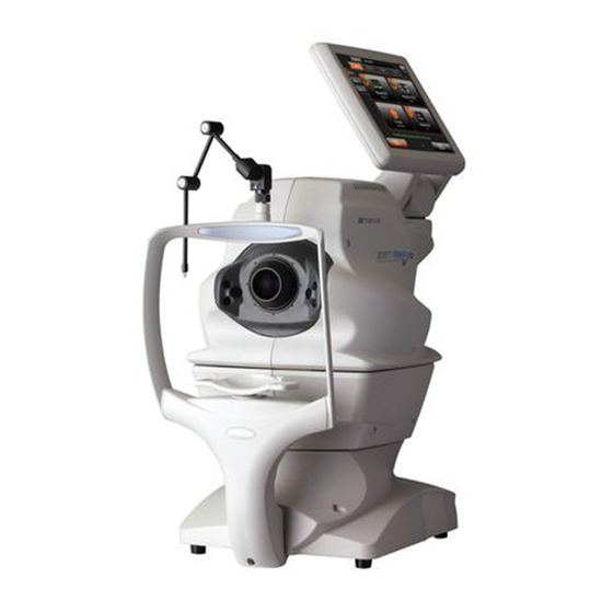
SYSTEM DIAGRAM COMPONENT NAMES External fixation target Control panel Main unit External I/O terminal cover Chin-rest unit Forehead rest *1 Peripheral fixation target *3 Objective lens Anterior segment stereoscopic Canthus marker camera *2 Chin-rest paper pin Chin-rest *1 Power switch Power supply unit *1: Contacting part (class B) *2: This unit is placed at the right and left sides of objective lens. -
Page 13: Operation Method Of Control Panel
OPERATION METHOD OF CONTROL PANEL Operate the control panel with your fingers or the attached touch pen. Do not use any sharp tools; NOTES e.g. ball point pen. The touch panel may be damaged to cause an incorrect opera- tion. Tap ... - Page 14 Capture icon selection screen You can select the optimal mode for various types of photography. Patient ID display area Status display area [MENU] button [SET UP] button Capture icon display area Capture eye selection button [MENU] button : Shifts to the capture icon selection screen. This does not operate on the capture icon selection screen.
- Page 15 Photography screen (Chin-rest adjustment) As watching the anterior segment observation image and the image of the anterior segment stereo- scopic camera, adjust the chin-rest. Patient ID display area Capture information display area [MENU] button 1234ABCD Operation guide Movie area 2 Movie area 1 Chin-rest up/down...
- Page 16 External fixation target : Tap this button, and the external fixation target is selected. Displays the selector button status (ON/OFF) of the external fixation target. You can change ON/ OFF of the external fixation target with this button. Displays the status of the internal fixation target. (Background is gray.) Displays the status of the external fixation target.
- Page 17 Photography screen (Chin-rest adjustment): Advance mode When you set "ON" for the "Advance" mode on the screen where you adjust the chin-rest as watching the anterior segment observation image and the image of the anterior segment stereoscopic camera, this screen appears. Color fundus photography ON/OFF button Small pupil diaphragm selector button [MENU] button...
- Page 18 Diopter compensation : Tap [+LENS] to increase the power. Tap [-LENS] to decrease the power. lens selector button The center button displays "No compensation lens". • When the patient's eye has a strong myopia, set the diopter compensation lens selector button to (-). When the patient's eye has a strong hyperopia, set the diopter compensation lens selector button to (+).
- Page 19 Photography screen (Automatic alignment to pupil) To avoid injury of the patient, be careful not to hit the patient with the CAUTIONS instrument during automatic alignment. This screen is used to perform automatic alignment to pupil. Alignment is performed by the image of the right and left anterior segment stereoscopic cameras.
- Page 20 Photography screen (Manual alignment to pupil) This screen is used to perform manual alignment to pupil. Tap the pupil displayed on Camera 1 and Camera 2. 1234ABCD Operation guide Movie area 1 Movie area 2 Processing message Capture start [BACK] button button Operation guide...
- Page 21 Photography screen (Automatic optimizing) This screen is used to perform automatic optimizing to fundus. 1234ABCD Movie area 2 Interference figure Movie area 1 display area Processing message Automatic IQ value display area adjustment stop button Movie area 1 : Displays the fundus image or the anterior segment observation image.
- Page 22 Photography screen (waiting for fundus capture to start) This screen shows the status while for the fundus capture to start. Make sure that all areas are encir- cled with green frames. When the green frame is not displayed, tap the [Capture STOP] button to stop photographing.
- Page 23 Photography with "3D: Optic disc" and "3D: Wide" When you perform the photography with "3D: Optic disc" and "3D: Wide", the following screens appear. Make sure that the optic disc is within the red frame on the screen. If the optic disc is not so, press the [Capture STOP] button.
- Page 24 Photography result display (The system shifts to the next photographic capture ses- sion by tapping the [OK] button.) Preview is displayed per shooting. In the case of both eyes, the system shifts to the next photographic capture session by tapping the [OK] button. When color fundus photography is set to OFF or when the instrument without the fundus photography function is used, the color fundus photography image is changed to the IR fundus photography image.
- Page 25 Photography screen (Manual adjustment mode) This screen is used to perform adjustment manually. 1234ABCD Area 1 Tomogram live image area Area 2 Area 3 Area 1 : Displays the image of the anterior segment stereoscopic camera and per- forms alignment with the fundus move button and the base back-and-forth button.
- Page 26 Area 1 Area 1 displays the image of the anterior segment stereoscopic camera and performs alignment with the fundus move button and the base back-and-forth button. When alignment is correct, the area is encircled with a green frame. Base back-and-forth button Fundus move button Pupil detection mark ...
- Page 27 Area 2 Area 2 displays the fundus/anterior segment live image. Area 2 on the manual adjustment mode screen displays the fundus or anterior segment live image, flash level, illumination level and the graphic image of the scan pattern, which is set in the selected capture icon, with an interrupted line.
- Page 28 Flash level display: Displays the flash level in nine steps (value range: -4 - +4). You can adjust the flash level by tapping the screen. (Refer to page 73.) While the xenon lamp power supply is being charged, the icon blinks. When charging is finished, the icon is lit.
- Page 29 Tomogram live image area This area displays the tomogram live image. Perform the operation on the live image. Z lock position Z lock position display bar Live image Image Quality value (IQV) [Image Quality] level meter Z lock position : Displays the center position of the displayed tomogram. After the processing of "Auto Z (Z Lock)"...
- Page 30 Image Quality value (IQV) : Displays the "Image Quality" level with a value. Image Quality value (IQV) is the image quality evaluation standard peculiar to TOPCON. IQV shows the image quality of the tomograms obtained by the 3D OCT-1 with a value quantitatively. When you need a tomogram applicable to NOTES image analysis or other processing, the IQV must be 30 or higher.
- Page 31 [Manual] button : Press the [Manual] button and operate the Z lock tab and [Rough opera- tion] button to perform optimizing. This button is displayed only when the "Advance" mode is set. [Rough operation] button Z lock tab [Rough operation] button •...
- Page 32 External fixation target selector button Tap this button, and the external fixation target is selected. You can change ON/OFF of the external fixation target with this button and the status (ON/OFF) of the external fixation target is displayed. When the external fixation target is ON, the internal fixation target shape selector button is faded out and displayed in gray.
- Page 33 Photography screen (Tomogram scan position: Manual adjustment) Tap the fundus/anterior segment live image area in Area 2, and the system shifts to the scan position adjustment screen. Tap the inside of the adjustment range, and you can change the scan position without using the buttons.
- Page 34 Scan position : Displays the range for the "scan width × scan width" of the scan line at the adjustment range (blue) focal point on the fundus. In the case of a tomogram within this range, you can obtain the sufficient output sensitivity. Scan possible range : Displays the range of "12.0mm×12.0mm"...
- Page 35 Photography screen (Internal fixation target position: Manual adjustment) 1234ABCD Fixation target Internal fixation target position adjustment button Fixation target position External fixation target selector button initialization button Fixation target shape selector button Fixation target : Indicates the fixation target position. Internal fixation target : Tap the upper, lower, right and left buttons when the fixation target is dis- position adjustment...
- Page 36 Photography screen (Focus: Manual adjustment) Press the [Focus] button, and the system shifts to the Focus manual adjustment screen. This screen is displayed only when the [Advance] button is ON. 1234ABCD Manual focus setting button Diopter compensation lens selector button Split lines Focus position display...
- Page 37 Photography screen (Picture angle change/adjustment) 1234ABCD Picture angle selector button Picture angle selector : This is displayed in color fundus photography, peripheral fixation target pho- button tography and anterior segment photography. Set this button to "ON", and "30° " is displayed in the photography information display area. The system enlarges the fundus or anterior segment image to be equal to the picture angle 30°...
- Page 38 Setting menu screen You can set many kinds of data for this instrument on this screen. On the capture icon selection screen, which is the initial screen, press the [SET UP] button. This screen appears. Capture select screen Set the icon display on the capture icon select screen and the parameters for each capture icon.
- Page 39 [Add icon] button : Adds the icon, which is selected on the capture icon list, to the icon layout setting area. When you select a capture icon in the icon layout setting area, the icon is added to the left side or upper right corner of the capture icon.
- Page 40 Parameter setting screen Set the parameters for the capture icon selected in the icon layout setting area. Capture icon name Function button Item name Item value selector button Cancel button OK button Function button : Saves and cancels the setting. Display of the capture icon : Displays the selected capture icon name.
- Page 41 Photography setting screen Auto operation setting screen System setting screen You can set data about photography and system. Function button Item button Utility button Item value display area Page number Page forward/backward button Function button : Saves and cancels the setting. Page number : Displays the current setting menu page's number in page order.
-
Page 42: Standard Accessories
User manuals (Instrument body / software) and Unpacking and assembly manual (1 each) Analysis software DVD (1) UNPACKING AND ASSEMBLY MANUAL 3D OPTICAL COHERENCE TOMOGRAPHY 3D OCT-1 USER MANUAL (for instrument body) 3D OPTICAL COHERENCE TOMOGRAPHY 3D OCT-1 SYSTEM DIAGRAM... -
Page 43: Preparations
PREPARATIONS INSTALLATION • The instrument should be moved by two people holding the bottom of the device. Be sure to hold the bottom with two people. To avoid injury, be aware of projections at the bottom. Carrying by one person may cause harm to his/her back or injury by falling parts. -
Page 44: Connecting The Power Cord
CONNECTING THE POWER CORD • Be sure to connect the power plug to an AC 3-pin receptacle equipped with grounding. Connection to a receptacle without grounding may CAUTIONS cause fire and electric shock in the case of shortcircuiting. • To avoid electric shocks, do not handle the power plug with wet fin- gers. -
Page 45: Connecting The External I/O Terminals
Use the external device conforming to IEC60950/IEC60950-1. NOTES For connecting to an external device, contact your TOPCON dealer or the offices listed on the back cover. DATA OUTPUT This product can be connected to a personal computer (PC) and other external devices via LAN. -
Page 46: Recovery From Power Save Status
RECOVERY FROM POWER SAVE STATUS This instrument adopts the power save system for saving electric power. When the machine is not operated for a set time, the control panel becomes a power save. Tap the control panel. In a few seconds, the measurement screen will be displayed and measurement is enabled. The time to start the power save status can be changed in the System setting NOTES menu "Power Save Timer (Min)". -
Page 47: Basic Operations
:Operations of instrument body :Operations of PC Preparation for Photography Turn on the power (Page46) Starting the 3D OCT-1 Program Selecting the Patient and Setting the Photography (Page47~51) Search the Patient information Register a New Patient... -
Page 48: Preparation For Photography
PREPARATION FOR PHOTOGRAPHY Turn ON the power Check the power cord connection. For details, see "CONNECTING THE POWER CORD" on page 42. Turn ON the of the instrument. POWER SWITCH POWER SWITCH Confirm that the Title screen is displayed and then, in several tens of seconds, the capture icon selection screen should be displayed. -
Page 49: Selecting The Patient And Setting The Photography
Selecting the Patient and Setting the Photography Please see page 24 on "3D OCT-1 User manual PC Software edition" for more NOTES information. Search the Patient information If the patient information already exists in database, select the patient from the Search Patient panel. - Page 50 Register a New Patient Register the patient information for new patients. When entering the patient ID through the 3D OCT-1, a bar code reader, a card reader, IMAGEnet, Multi-Viewer, etc., you must use only the alphabet, numerals and "-". NOTES Moreover, the following symbols cannot be used for the patient ID.
- Page 51 Selecting the Patient Select the patient from the Search Patient panel. Then, click the [Capture] button. [Capture] button Selected patient Photography screen appears. BASIC OPERATIONS...
- Page 52 Selecting the capture icon and selecting the eye On the capture icon selection screen, which is the initial screen, tap and select the fundus tomogramcapture icon. 1234ABCD You can select and display a capture icon from the icons shown in the following table. Color Capture icon Scan...
- Page 53 Color Capture icon Scan Fixation Over Scan Capture icon Scan length Anterior name resolution position Count Photography 5Line Cross 9.0mm 1024 Macula 3D Wide 12.0×9.0mm 512×128 Wide Select an eye to be captured. 1234ABCD Capture eye selection button BASIC OPERATIONS...
-
Page 54: Fundus Tomography
FUNDUS TOMOGRAPHY • When selecting a patient, the base is initialized. To avoid injury of the patient, instruct the patient to move away his/her chin from the chin- rest. • Caution in photography Under the following photography conditions, there is a bright spot on the center of the picture. - Page 55 Adjust the table height or chair height so the patient can relax with his/her chin placed cen- trally on the chin-rest. Let the patient rest his/her chin on the chin-rest. Adjust the chin-rest height by adjusting the chin-rest up/down button so the outside corner of the patient's eye is level with the Canthus marker on the chin-rest post.
- Page 56 After automatic alignment, automatic focus starts. • When automatic operation is not possible for certain reasons, the manual adjustment screen is automatically accessed. You can also access the man- NOTES ual adjustment screen by tapping the [Capture STOP button]. For operation on the manual screen, refer to "...
- Page 57 Photography screen (OCT automatic photography) After adjusting the chin position with the chin-rest up/down button, press the capture start button. Automatic photography starts. The following steps are automatically executed in the order listed below. Alignment to pupil is performed automatically. 1234ABCD Automatic focus and automatic optimizing to fundus are performed automatically.
- Page 58 The system shifts to the waiting status for the capture start and the capture timer starts. After the given time has passed on the capture timer, photography starts automatically. 1234ABCD After the photograph is taken, the result is automatically displayed. When color fundus photography is set to OFF or when the instrument without the fundus pho- tography function is used, the color fundus photography image is changed to the IR fundus photography image.
- Page 59 Check for photography result When the photography result is OK. : Tap the [OK] button. Where OU photography is selected, shift to the photography for the other eye. To photograph the other eye, operate as indicated in step and below on page 53. Where single eye is selected or both eyes have been photographed, back to the step [Select- ing the capture icon and selecting the eye] on page 50.
-
Page 60: Check For Photographic Data And Report Output
Check for photographic data and report output Select the thumbnail that has been analyzed, and the button on the tool bar are validated.In some of the scan patterns, these buttons are not validated. After displaying the report, click the [Export]. After finishing the export, click the [Menu] button to back to the patient searching screen (page 47). -
Page 61: How To Shut Down
HOW TO SHUT DOWN Shutting down the personal computer Exit this software. Turn off the personal computer according to its regular shut down method. Shutting down the instrument Turn OFF ( ) the of the instrument. POWER SWITCH • When the instrument is not in use for a long time, unplug the power cords of the instrument, external recording device and others from the outlet and remove the cords from each device. -
Page 62: Objective Operations
OBJECTIVE OPERATIONS COLOR FUNDUS PHOTOGRAPHY * Fundus cannot be photographed by the instrument without the fundus photography function. • When selecting a patient, the base is initialized. To avoid injury of the patient, instruct the patient to move away his/her chin from the chin- rest. - Page 63 Photography screen (Color fundus automatic photography) After adjusting the chin position with the chin-rest up/down button, press the capture start button. Automatic photography starts. The following steps are automatically executed in the order listed below. Alignment to pupil is performed automatically. 1234ABCD Automatic focus to fundus is performed automatically.
- Page 64 The system shifts to the waiting status for the capture start and the capture timer starts. After the given time has passed on the capture timer, photography starts automatically. 1234ABCD After the photograph is taken, the result is automatically displayed. 1234ABCD OBJECTIVE OPERATIONS...
- Page 65 Setting the picture position Using the on Area 1 of the photography screen (color INTERNAL FIXATION TARGET POSITION SELECTOR BUTTON photography), set the picture position. Each time you press the , the picture position is changed to "D" (optic disc INTERNAL FIXATION TARGET POSITION SELECTOR BUTTON center), "C"...
-
Page 66: Color Anterior Segment Photography
COLOR ANTERIOR SEGMENT PHOTOGRAPHY * Anterior segment cannot be photographed by the instrument without the fundus photography function. To avoid injury of the patient, be careful not to bump the patient's eye or CAUTIONS nose with the instrument and external fixation target when operating the control panel. - Page 67 After the photograph is taken, the result is automatically displayed. 1234ABCD OBJECTIVE OPERATIONS...
-
Page 68: Fundus Peripheral Photography
FUNDUS PERIPHERAL PHOTOGRAPHY * Fundus periphery cannot be photographed by the instrument without the fundus photography function. To avoid injury of the patient, be careful not to bump the patient's eye or CAUTIONS nose with the instrument and external fixation target when operating the control panel. - Page 69 Peripheral photography After adjusting the chin position with the chin-rest up/down button, press the capture start button. Automatic photography starts. Before starting the photography, make sure that the desired fixation tar- get is selected. The following steps are automatically executed in the order listed below. Alignment to pupil is performed automatically.
- Page 70 The system shifts to the waiting status for the capture start and the capture timer starts. After the given time has passed on the capture timer, photography starts automatically. 1234ABCD After the photograph is taken, the result is automatically displayed. Press the [OK] button, and the system returns to the screen where the next fixation position is selected.
- Page 71 Photography screen (when automatic photography has failed) If an error message is displayed during automatic photography, perform adjustment by manual photog- raphy. Then, press the capture start button to continue the photography. • If an error has occurred during automatic alignment to pupil: If the patient's face or eye cannot be detected or the pupil center is not tracked, the following mes- sages are displayed.
- Page 72 • If an error has occurred during the following process: The system shifts to the waiting status for the capture start and the capture timer starts. After the given time has passed on the capture timer, photography starts automatically. If any trouble such as blink is detected right before photography, shift to the manual adjustment mode.
- Page 73 Operation on the manual adjustment screen During manual adjustment, the photography screen is shown below. See P.23. For details of each operation, refer to each photography screen. For setting the flash level, refer to "Photography screen (Manual adjustment mode)" (P.23). For adjusting the scan position, refer to "Photography screen (Tomogram scan position: Manual adjustment)"...
- Page 74 Setting the picture position If necessary, you can change the default picture position, which is set according to the selected cap- ture icon, to the external fixation target. There are the following three changing methods. Please change the picture position by your desired method.
- Page 75 Setting the illumination level Press the [Advance] button on Area 3 of the photography screen (OCT photography). Tap the "+" of the [Illumination level] display on the fundus/anterior segment live image area, and the illumina- tion level increases. Tap the "-", and the illumination level decreases. Illumination level Illumination level decreases.
-
Page 76: Deleting Data
Changing the diopter compensation lens Press the [Advance] button on Area 3 of the photography screen (OCT photography). Then, press the [Manual focus setting button] on the fundus/anterior segment live image area. Tap the diopter com- pensation lens selector button and change the diopter compensation lens for the patient's eye. 1234ABCD Diopter compensation lens selector button... -
Page 77: Saving Data
SAVING DATA Data is saved on the personal computer. For details, refer to the instruction manual (for software). PRINTING DATA Data is printed on the personal computer. For details, refer to the instruction manual (for software). OBJECTIVE OPERATIONS... -
Page 78: Details Of The Setting Menu
DETAILS OF THE SETTING MENU On the setting menu screen, you can set a variety of data. Preparation for setting Check the power cord connection. For details, see "CONNECTING THE POWER CORD" on page 42. Turn ON (I) the of the instrument. POWER SWITCH Displaying the setting menu screen Check the capture icon selection screen, which is the initial screen. - Page 79 PAGE 1: Capture Icon Setting On the "PAGE 1" screen, set the icon display for the capture icon, which is displayed on the capture icon selection screen, and the parameters for each capture icon. For details on the buttons, refer to page 36 and page 38.
- Page 80 Press the button. Delete icon Make sure that the icon is deleted. The remaining icons are moved to the left side or upper right corner. DETAILS OF THE SETTING MENU...
- Page 81 How to add the displayed icon Tap and select the capture icon to be added from the capture icon list. (It is highlighted.) Press the button. Add icon DETAILS OF THE SETTING MENU...
- Page 82 Make sure that the icon is added. DETAILS OF THE SETTING MENU...
- Page 83 How to check and change the parameters for the icons: Tap and select the icon of the capture icon for which the parameters should be checked and changed in the icon layout setting area. (It is highlighted.) Press the button at the bottom of the screen.
- Page 84 The parameter setting screen appears. Tap the item button whose setting should be changed. The selectable item values are displayed. Tap and change the value to the desired one. Press the [OK] button to decide the change. If you press the button, the value before changing is set again and the system exits from the Cancel parameter setting screen.
- Page 85 Item buttons for setting parameters (1) Scan Pattern Scan pattern means the shape or kind to be scanned. It is classified into the following 6 kinds: Line: Scans linearly. You can scan the range (Scan Size) with the horizontally-set resolution (Scan Resolution) and display the scanned object as a stereograph.
- Page 86 (7) Color Anterior Photography This can be set only when "Fundus Photography" is selected. Takes a color picture of anterior segment. This item cannot be set in the instrument without the fundus photography function. The fixation position is set to "External" (external fixation target) and this cannot be changed. (8) Step This is valid only when the "5 Line Cross"...
- Page 87 PAGE 2: Photography Setting On the "PAGE 2" screen, you can set a variety of data for photography. For the details on each button, refer to page 39. PAGE 2: Initial screen On PAGE 2, the items shown in the following table are assigned to the buttons on each layer. Utility button Item button Item selector button...
- Page 88 Utility button Item button Item selector button shipment Fundus Blink Detection Level Photo Normal OCT+Color Mode High ISO • Changes the color fundus image quality Normal ISO (High/Normal/Low). Low ISO Flash Level (OCT+Color Mode) 1.0 - 25.9W•s Gain (OCT+Color Mode) 0 - 9, BS, AC *2 Color Mode High ISO...
- Page 89 PAGE 3: Auto Operation On the "PAGE 3" screen, set the Auto functions. For details on each button, refer to page 39. PAGE 3: Initial screen On PAGE 3, the items shown in the following table are assigned to the buttons on each layer. Utility button Item button Item selector...
- Page 90 Utility button Item button Item selector button shipment Auto Optimize ON/OFF Auto Z • Detects the retina posi- tion automatically, and always displays the fun- dus tomogram clearly during observation. Z-lock After Auto Z • After "Auto Z", the pho- tographed fundus image is fixed.
- Page 91 PAGE 4: System Setting On the "PAGE 4" screen, set the system. For details on each button, refer to page 39. PAGE 4: Initial screen On PAGE 4, the items shown in the following table are assigned to the buttons on each layer. Utility button Item button Item selector button...
- Page 92 Capture icon protocol The following table shows the parameters in each capture icon. : Initial set value Capture Icon Capture Icon Color Fundus Scan Size Scan Fixation OCT Focus Over Scan Color Anterior Raster Scan Re-scan OCT Live name Photography Resolution Position Position...
-
Page 93: Before Requesting Service
BEFORE REQUESTING SERVICE TROUBLESHOOTING Messages during operation Error message Contents Out of memory. Please turn the power The memory area used by the built-in OS (Operating System) is not switch OFF and try again. sufficient. CIBT board error(Error Code:xxx) An error has occurred in the built-in image board. Error code is displayed on "xxx"... - Page 94 Error message Contents SLD memory error. Please turn the power It is probable that the SLD light intensity is not normal. switch OFF. SLD pulse lighting error. Please turn the It is probable that the SLD light intensity is not normal. power switch OFF.
- Page 95 When an error is encountered, review the Check List below. After following the instructions below, if you still have difficulty or if the problem does not fall into any of the categories listed below, contact your dealer or TOPCON (see the back cover). Check List...
- Page 96 Problem Condition Check Page Alignment is incorrect. Internal fixation target Adjust alignment. cannot be seen. Internal fixation target is set to the "D" Press the internal fixation target position or "M" side. selector switch to move it to "C". ...
-
Page 97: Specifications And Performance
SPECIFICATIONS AND PERFORMANCE SYSTEM DIAGRAM This instrument is composed of the following three units. Main body unit Power supply unit Chin-rest unit Main unit Control panel Control Image CPU PCB board Fundus optical system Interference system/ spectroscope Chin-rest unit XYZ drive unit terminal... -
Page 98: Specifications By Items
SPECIFICATIONS BY ITEMS Item Specifications Observation & photographing of the fundus (Note 3) (Note 1) (Note 4) • Type of photography Color , Red-free & IR • Picture angle for 45° ±5% or less (Note 3) observation/photography 30° or equivalent (digital zoom) •... -
Page 99: Other Specifications
OTHER SPECIFICATIONS Measurable range of dioptric power for the patient's eye Without the diopter compensation -13D to +12D (in fundus photography) Note 1) lens When the concave compensation -12D to -33D (in fundus photography) lens is used When the convex compensation +11D to +40D (in fundus photography) lens is used SLD light source... -
Page 100: Electromagnetic Compatibility
Guidance and manufacturer's declaration - electromagnetic emissions The 3D OCT-1 is intended for use in the electromagnetic environment specified below. The customer or the user of the 3D OCT-1 should assure that it is used in such an environment. Emissions test... - Page 101 Guidance and manufacturer's declaration - electromagnetic immunity The 3D OCT-1 is intended for use in the electromagnetic environment specified below. The customer or the user of the 3D OCT-1 should assure that it is used in such an environment. IEC 60601...
- Page 102 Guidance and manufacturer's declaration - electromagnetic immunity The 3D OCT-1 is intended for use in the electromagnetic environment specified below. The customer or the user of the 3D OCT-1 should assure that it is used in such an environment. Immunity test...
-
Page 103: Requirements For The External Device
RF communications equipment and the 3D OCT-1 The 3D OCT-1 is intended for use in an electromagnetic environment in which radiated RF distur- bances are controlled. The customer or the user of the 3D OCT-1 can help prevent electromagnetic... -
Page 104: Patient's Environment
PATIENT’S ENVIRONMENT When the patient or inspector comes into contact with the devices (including the connecting devices) or when the patient or inspector is in contact with the person that touches the devices (including the con- necting devices), the patient's environment is shown below. In the patient's environment, use devices conforming to IEC60601-1. -
Page 105: Specifications Of The Personal Computer (Commercial Product) To Be Connected
SPECIFICATIONS OF THE PERSONAL COMPUTER (COMMERCIAL PRODUCT) TO BE CONNECTED Item Operation spec. Recommended spec. Windows 7 Professional 32bit / 64bit Windows 7 Professional 32bit / 64bit (English) (English) Core2 DUO Core i7 (equivalent to 2600) Clock 3GHz 3.4GHz Core 4GB for Windows 7 32 bits 8GB for Windows 7 64 bits ... -
Page 106: General Information On Usage And Maintenance
- If the patient does not conform to these conditions, it is not possible to take a picture correctly. INTENDED USER PROFILE The 3D OCT-1 3D Optical Coherence Tomography is an electric instrument for medical use. Use this instrument under a doctor's guidance. -
Page 107: Environmental Conditions For Packaging In Storage
ENVIRONMENTAL CONDITIONS FOR PACKAGING IN STORAGE Temperature : -20°C to 50°C Humidity : 10% to 95% ENVIRONMENTAL CONDITIONS FOR PACKAGING IN TRANSPORTAION Temperature : -40°C to 70°C Humidity : 10% to 95% ELECTRIC RATING Source voltage : AC 100 - 240V 50-60Hz Power input : 70 - 150VA DIMENSIONS AND WEIGHT... -
Page 108: System Classification
Degree of protection against harmful ingress of water: IPx0 The 3D OCT-1 has no protection against ingress of water. (The degree of protection against harmful ingress of water defined in IEC 60529 is IPx0.) Classification according to the method(s) of sterilization or disinfection recommended by the manu- facturer: not applicable. -
Page 109: Operation Principle
OPERATION PRINCIPLE The patient's eye is illuminated by near infrared light, which is emitted by the fundus illumination optical (Note 1) system (IR LED and xenon lamp ). The fundus observation/photography optical system forms an image on the image pick-up element (fundus observation camera), and the image can be observed on the control panel. -
Page 110: Checkpoints For Maintenance
5. When the objective lens is stained, clean it according to "Cleaning the objective lens" in this manual. DISPOSAL • When disposing of 3D OCT-1 parts, follow the local regulations for disposal and recycling. This symbol is applicable for EU member countries only. -
Page 111: Maintenance
When not in use, always turn the OFF ( ). POWER SWITCH ORDERING CONSUMABLES When ordering consumables and spare parts, contact your dealer or TOPCON (see the back cover) and tell them the article name, article code and quantity. Article name Article code... -
Page 112: Replacing The Xenon Lamp
REPLACING THE XENON LAMP * The xenon lamp is not mounted on the instrument without the fundus photography function. To avoid electric shock and burns, do not replace the lamp by yourself. CAUTIONS Ask your dealer for repairs. MAINTENANCE... -
Page 113: Refilling The Chin-Rest Paper Sheet
REFILLING THE CHIN-REST PAPER SHEET When the chin-rest paper sheet is used up, pull out the chin-rest paper pin and refill the paper sheet. Chin-rest paper pin MAINTENANCE BY THE DEALER Item Inspection interval Details Cleaning the external section Cleaning each Within 12 months from ... -
Page 114: Cleaning
CLEANING Cleaning the external cover, control panel and other parts To avoid damage to the instrument or injury due to electric shock, turn CAUTIONS off the power switch and remove the power cord before cleaning the instrument. • Do not spray liquid on the instrument. The instrument may be damaged or those that come into contact with the instrument may be injured by electric shock. - Page 115 • Don't let any strong-alkaline liquid adhere to the objective lens. If such a liquid adheres to the lens, immediately wipe it off. • If it is difficult to remove a stain from the objective lens, contact your dealer or TOPCON (see the back cover). MAINTENANCE...
-
Page 116: Optional Accessories
OPTIONAL ACCESSORIES ATTACHMENT FOR ANTERIOR SEGMENT HA-2 When you want to take a picture of the patient's ante- rior segment, use this attachment. By mounting this attachment onto the instrument's forehead rest, it is possible to take a tomogram of anterior segment. -
Page 117: Reference Material
REFERENCE MATERIAL SCAN PATTERN SPECIFICATIONS Line Scan In the scan range, move on the line (blue line in the figure below), which connects the coordinates of the given start point and end point, by the step divided by the given resolution. Be sure to move from the start point to the end point. - Page 118 3D Scan Move on the inside of the square, which is composed of the given start point and end point, horizontally and vertically by the step divided by the given resolution. The scan for [3D Macula] and [3D Disc] is shown below. ("6.0×6.0mm" is initially set for the scan length in both of these scans.) [3D-Scan] Right eye...
-
Page 119: Type Of Plug
TYPE OF PLUG Country Voltage/frequency Type of plug Mexico 110V/50Hz Type C&E Argentina 220V/60Hz Type A Peru 220V/60Hz Type A Venezuela 110V/50Hz Type C&E Bolivia & Paraguay 220V/60Hz Type A (Most common) Type H (Infrequently) Chile 220V/60Hz Type A Colombia 110V/50Hz Type C Brazil... -
Page 120: Relation Between The Setting Of The Illumination/Flash Level And Maximum Radiance
RELATION BETWEEN THE SETTING OF THE ILLUMI- NATION/FLASH LEVEL AND MAXIMUM RADIANCE When the maximum radiance is "1", the ratio of radiance is shown below in the setting of the illumination/ flash level. Illumination level Ratio of Display level radiance 0.354 0.500 0.707... -
Page 121: 3D Oct-1 Software License Terms
Digia Plc and its licenser posses the copyright and the intellectual property right of the "Qt" soft- ware installed in 3D OCT-1. TOPCON CORPORATION grants to you the right to use this 3D OCT-1 Software under the terms and conditions outlined below. - Page 122 LICENSE TERMS. 7. LIMITED WARRANTY 7.1 In the event that a hidden material defect is found by USER, USER shall notify TOPCON in writing of such defect directly or through its subsidiary, affiliate, distributor or agent within ninety (90) days after USER has received the SOFTWARE.
- Page 123 THE ENTIRE RISK ARISING OUT OF, RESULTING FROM OR IN CONNECTION WITH THE USE OR PERFORMANCE OF THE SOFTWARE REMAINS WITH THE USER. IN NO EVENT SHALL TOPCON OR ITS SUBSIDIARIES, AFFILIATES, DISTRIBUTORS OR AGENTS BE LIABLE FOR ANY CONSEQUENTIAL, INCIDENTAL, DIRECT, INDIRECT, SPECIAL, PUNITIVE, OR OTHER...
- Page 124 TERMS shall be governed by and under the laws of Japan. 11. ENTIRE AGREEMENT These LICENSE TERMS constitute the entire agreement between USER and TOPCON with respect to the subject matter hereof, and shall supersede and cancel any and all prior written or oral agreements, undertakings, negotiations, communications, commitments, representations, publications and adver- tisement, etc.
- Page 125 Defective condition: Please provide us with as much detail as possible on the problem. 3D OPTICAL COHERENCE TOMOGRAPHY 3D OCT-1 USER MANUAL The 2013 version (2013.07-100TH Date of issue: July 3, 2013 Published by TOPCON CORPORATION 75-1 Hasunuma-cho, Itabashi-ku, Tokyo, 174-8580 Japan. ©2013 TOPCON CORPORATION ALL RIGHTS RESERVED...
- Page 126 3D OPTICAL COHERENCE TOMOGRAPHY 3D OCT-1 47010 91942 Printed in Japan 1307-100TH...
Need help?
Do you have a question about the 3D OCT-1 and is the answer not in the manual?
Questions and answers
HOW DO I DELETE PHOTOS
I have a TOPCON 3D OCT-1 , This error apears: CIBT bord error (0x4b8_013f) file name (octscan.cpp) line 4757 how can I fix , please