
Related Manuals for Topcon DRI OCT-1 Triton


Summary of Contents for Topcon DRI OCT-1 Triton
- Page 1 USER MANUAL 3D OPTICAL COHERENCE TOMOGRAPHY DRI OCT-1 Model Triton DRI OCT-1 Model Triton (plus)
-
Page 3: Introduction
INTRODUCTION Thank you for purchasing the TOPCON DRI OCT-1 Model Triton 3D Optical Coherence Tomography. INTENDED USE / INDICATIONS FOR USE The TOPCON DRI OCT-1 Model Triton is a non-contact, high-resolution tomographic and bio-micro- scopic imaging device. It is indicated for in-vivo viewing, axial cross-sectional and three dimensional... - Page 4 3. The contents of this manual are correct to the best of our knowledge. Please inform us of any ambiguous or erroneous descriptions, missing information, etc. 4. Original Instructions This manual was originally written in English. ©2015 TOPCON CORPORATION ALL RIGHTS RESERVED...
-
Page 5: Table Of Contents
CONTENTS INTRODUCTION ......................... 1 DISPLAYS AND SYMBOLS FOR SAFE USE ..............5 GENERAL SAFETY INFORMATION ..................6 HOW TO USE THIS MANUAL ....................8 GENERAL MAINTENANCE INFORMATION ..............8 DISCLAIMERS ..........................8 POSITIONS OF WARNING AND CAUTION INDICATIONS .......... 9 STANDARD ACCESSORIES .................... - Page 6 CLEANING THE OBJECTIVE LENS ..................... 93 BEFORE REQUESTING SERVICE ....................94 TROUBLESHOOTING ........................94 SPECIFICATIONS AND PERFORMANCE ................101 SYSTEM DIAGRAM ........................101 SPECIFICATIONS ........................102 OTHER SPECIFICATIONS ......................103 SPECIFICATIONS OF THE PERSONAL COMPUTER (COMMERCIAL PRODUCT) TO BE CONNECTED ....................104 SAFETY OF LED PRODUCT .......................
-
Page 7: Displays And Symbols For Safe Use
DISPLAYS AND SYMBOLS FOR SAFE USE To encourage safe and proper use and to prevent injury to the operator and others or potential damage to property, important messages are put on the instrument body and inserted in the manual. We suggest that everyone understand the meaning of the following displays, icons and text before read- ing the "GENERAL SAFETY INFORMATION"... -
Page 8: General Safety Information
GENERAL SAFETY INFORMATION CONTRAINDICATION When used for red-free photography only, this instrument must not be used for the following patients. • Patients who are hypersensitive to light • Patients who recently underwent photodynamic therapy (PDT) • Patients taking medication that causes photosensitivity. WARNING Ensuring the Safety of Patients and Operators Be careful not to hit the patient's eyes or nose with the instrument during operation. - Page 9 To avoid electric shock, do not insert metal objects into any vents and/or slots. To avoid electric shock, do not open the instrument. Request service from an authorized Topcon distributor. Do not put any substance over the vent on the top surface of the power supply unit. If the vent is cov- ered, the temperature of the power supply unit may rise abnormally to cause a malfunction.
-
Page 10: How To Use This Manual
When the customer has obtained data through this software and has saved or backed up the data in a server or personal computer, TOPCON shall not take any responsibility for the loss of the data, loss of profit or other damages on the customer. -
Page 11: Positions Of Warning And Caution Indications
POSITIONS OF WARNING AND CAUTION INDICATIONS To ensure safety, this machine provides warning displays. Use the instrument correctly by observing the display instructions. If any of the following display labels are missing, contact your TOPCON dealer at the address listed on the back cover. -
Page 12: Standard Accessories
STANDARD ACCESSORIES Upon unpacking, make sure that all the following standard accessories are included. Figures in ( ) are the quantities. Power cord (1) Chinrest tissue (1) External fixation target (1) Monitor cleaner (1) User manual, Unpacking and Dust cover (1) assembly manual and Analysis software DVD (1 each) UNPACKING AND ASSEMBLY MANUAL... -
Page 13: Components
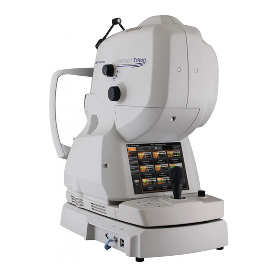
COMPONENTS COMPONENT NAMES Main unit External fixation target Diopter compensation lens External cover selector Lamp house cover screw Focusing knob Lamp house cover Touch display Photography button Control lever Vertical position mark Base clamping knob Control panel Power lamp Sliding board External connection terminal Power supply unit Forehead rest *1... -
Page 14: Control Panel Components
CONTROL PANEL COMPONENTS Small pupil diaphragm selector button Split button External fixation target selector button Base clamping knob Photography button Internal fixation target position move button Chinrest up/down button (Up/Down/Left/Right/Reset) Power lamp Chinrest up/down button : Adjusts the chinrest up/down movement. Internal fixation target : Adjusts the internal fixation target position finely. -
Page 15: Operation Method Of Touch Display
OPERATION METHOD OF TOUCH DISPLAY Operate the touch display by your fingers. Don't use any sharp tool such as a NOTE ball point pen. The touch display may be damaged to cause an incorrect operation. Tap → To select any relevant item. Touch the screen softly with a finger. -
Page 16: Names On The Touch Display
NAMES ON THE TOUCH DISPLAY Display areas and functions on the touch display Information is displayed on the touch display and you can perform a variety of operations by touch- ing the screen. Capture icon selection screen You can select the optimal mode for various types of photography. Patient ID display area Message display area Capture icon tab... - Page 17 Follow-up photography function in DRI OCT-1 Model Triton is as follows: the system searches the same scan position as the last photographed data* by using the live IR image of the present photography to decide the scan position. NOTE * "The last photographed data" means the data photographed at the date in the past.
- Page 18 Photography screen (OCT photography) Patient ID display area Timer button Area 1 Fundus/anterior segment live Tomogram image area live image area Area 2 Patients ID display area : Displays the patients ID. Timer button : Used in FA photography. (Refer to page 61.) (Only in DRI OCT-1 Model Triton plus) Area 1...
- Page 19 Area 1 Area1 displays the operation mode buttons.You can change to each mode. The current operation mode is highlighted in orange. The mode that cannot be selected according to the current status is displayed in gray unclearly. The mode cannot be selected even if you touch the button in this status.
- Page 20 • Scan position button The scan position adjustment mode is accessed. The selected scan pattern, the scan position adjustment range, the scan possible range (only in "Radial" and "5 Line Cross" scan) and other fine adjustment buttons are displayed on the fundus live image area. Radial scan Fine adjustment button (up) Button to reset the...
- Page 21 Scan position adjustment range (blue) Displays the "Scan width × Scan width" range at the focal point on fundus. In the "Scan width × Scan width" range, it is easy to obtain the sufficient output sensitivity for tomo- grams. Scan possible range (red) Displayed only for "5 Line Cross"...
- Page 22 Fundus/anterior segment live image area This area displays the fundus live image, the right/left eye, illumination level and besides, the graphic image of the scan pattern, which is set on the selected capture icon, with an interrupted line. You can set ON/OFF of the illumination level by the touch display.
- Page 23 In the case of left eye, "OS(L)" is displayed at the upper right position of the live image. In the case of right eye, "OD(R)" is displayed at the upper left position. • Illumination level display: Displays the illumination level (level) by five steps (value: 1 to 5). You can adjust the illumination level by touching the screen.
- Page 24 Tomogram live image area This area displays the tomogram live image. Perform the operation on the live image. Z lock position display bar Live image Z lock position [Image Quality] level meter [Optimize] button Image Quality value (IQV) Stereoscopic image [Manual] button •...
- Page 25 • Image Quality value (IQV) : Displays the "Image Quality" level with a value. • Image Quality value (IQV) is the image quality evaluation standard peculiar to TOPCON. IQV shows the image quality of the tomograms obtained by the DRI OCT-1 Model Triton with a value quantitatively. When you need a tomogram applicable to image analysis or other processing, the IQV must be 40 or higher.
- Page 26 Preview screen (OCT photography) After OCT photography, the preview screen shown below appears. Tomogram preview area Fundus photographed image Scanned range Delete button Tomogram preview area : Previews the photographed tomograms. When there are two or more images in "3D" or "Radial" scan, the typi- cal image is displayed in this area.
- Page 27 Setting menu screen You can set many kinds of data for this instrument on this screen. On the capture icon selection screen, which is the initial screen, press the [SET UP] button. This screen appears. • Capture select screen Set the icon display on the capture icon select screen and the parameters for each capture icon. Function button Menu selector button Capture icon tab...
- Page 28 [Add icon] button : Adds the icon, which is selected on the capture icon list, to the icon layout setting area. When you select a capture icon in the icon layout setting area, the icon is added to the left side or upper right corner of the capture icon.
- Page 29 • Parameter setting screen Set the parameters for the capture icon selected in the icon layout setting area. Capture icon name Item name Item value selector button Cancel button OK button Display of the capture icon : Displays the selected capture icon name. name Item name : Displays the objective items of the parameters for the selected cap-...
- Page 30 • Photography setting screen • Auto operation setting screen • System setting screen You can set data about photography and system. Function button Item button Utility button × Item value display area Page number Page forward/backward button Function button : Saves and cancels the setting. Page number : Displays the current setting menu page's number in page order.
-
Page 31: Preparations
PREPARATIONS INSTALLING THE INSTRUMENT • To prevent the instrument from falling and to avoid injury during carry- ing, be sure to secure the instrument with the base clamping knob at the bottom. • To avoid injury or damage, two people should be employed for sup- porting the instrument from the underside. -
Page 32: Connecting The Power Cord
CONNECTING THE POWER CORD To avoid fire and electric shock in case of leakage, be sure to use a WARNING power supply equipped with a 3-pin plug AC receptacle for proper grounding. CAUTION To avoid electric shock, do not handle the plugs with wet fingers. Make sure that the of the instrument body is OFF ( ). -
Page 33: Connecting The External Device
CONNECTING THE EXTERNAL DEVICE The connection terminals for external devices are arranged on the base unit. LAN terminal USB terminal • Use the external device complying with IEC60950-1. Do not connect any device that is not specified as a system. For details about connecting the external devices, contact your dealer or TOP- NOTE CON (see the back cover). -
Page 34: Reset From Power Save State
RESET FROM POWER SAVE STATE This machine adopts the power save method for power saving. When the instrument body (excluding the chin-rest up/down button and focusing knob) is not operated for a period of time, the power save function stops power supply to the touch display, illumination light source and photography light source. -
Page 35: Basic Operations
BASIC OPERATIONS FLOW OF OPERATION Turning on the power (P.34) Preparation for personal computer (P.34) • Inputting the patient information Setting the capture icon (P.35) Setting the patient (P.37) Setting the illumination level (P.40) Changing the diopter compensation lens (P.41) Alignment and photography (P.42) Transferring the data to the exter- nal personal computer... -
Page 36: Preparation For Photography
PREPARATION FOR PHOTOGRAPHY Connecting the power supply Check the power cord connection. For details, see "CONNECTING THE POWER CORD" on page 30. Turn ON ( ) the of the instrument. POWER SWITCH Confirm that the Title screen is displayed and then in a few seconds the capture icon selection screen should be displayed. -
Page 37: Fundus Tomography
FUNDUS TOMOGRAPHY To avoid injury of the patient, be careful not to bump the patient's eye or CAUTION nose with the instrument and external fixation target when operating the touch display. • Caution in photography Under the following photography conditions, there is a bright spot on the cen- ter of the picture. - Page 38 Capture icon Scan Fixation Myopia Over Scan Capture icon Scan length name resolution position Mode Count Line (H)/ 1024H/ 9.0mm Macula Line (V) 1024V 5 Line Cross 6.0mm 1024×10 Macula Radial Dir. 6.0mm 1024×12 Macula 3D: Macula 7.0×7.0mm 512×256 Macula 3D: Optic disc 6.0×6.0mm 512×256...
- Page 39 Setting up the patient • To avoid electric shock, do not touch the external connection terminal, the cable terminal from the external device and the patient at the same time. • When moving the chinrest up and down, be careful not to pinch the CAUTION patient's hand to avoid possible injury.
- Page 40 Setting the picture position To avoid injury of the patient, be careful not to bump the patient's eye or CAUTION nose with the instrument when operating the control lever or touch dis- play. You can change the default picture position, which is set according to the selected capture icon. If nec- essary, you can change the default position to the external fixation target.
- Page 41 • Changing by using the scan position button (touch display) Use this method when changing the scan position. Tap the on Area 2 of the photography screen (OCT photography) to SCAN POSITION BUTTON access the scan position adjustment mode. On the fundus live image area, the graphic image of the selected scan shape and range is displayed with a solid line.
- Page 42 Setting the illumination level Tap the "+" of the [Illumination level] display on the fundus/anterior segment live image area, and the illumination level increases. Tap the "-", and the illumination level decreases. Illumination level Illumination level decreases. increases. Illumination level display Setting the flash level To avoid discomfort to the patient, do not brighten the photography light...
- Page 43 Changing the diopter compensation lens Turn the diopter compensation lens selector to compensate the dioptric power for the patient's eye. Diopter compensation lens selector • When the patient's eye has a strong myopia, turn the diopter compensation lens selector and set it to (-). •...
- Page 44 Alignment and photography • To avoid injury while moving the instrument body, do not put your hand into the gap between the main unit and power supply unit. CAUTION • To avoid injury to the patient's eyes and nose while moving the instru- ment body, be attentive to the distance between the patient and the objective lens.
- Page 45 Hold the control lever and pull the instrument to the utmost limit toward the operator. As the internal fixation target turns on, instruct the patient to look at the fixation target in the center. Observe the anterior segment image on the touch display. Move the instrument body in right and left / up and down directions with the control lever until you get the patient's eye in the center of the fundus live image area.
- Page 46 When the pupil diameter is small, press the NOTE on the control panel to set the small SMALL PUPIL DIAPHRAGM SELECTOR BUTTON pupil diaphragm to "ON". Bring the base slowly toward the patient side, and the fundus image appears on the fundus live image area.
- Page 47 When the auto focus function is ON, the instrument automatically changes the split lines into one line. At this time, the fundus is almost in focus. The auto focus mechanism does not work for ocular pathology (e.g. strong cataract), myopia and hyperopia (beyond -13 to +12D), etc.
- Page 48 Operate the control lever up and down, right and left to bring the alignment bright spot into the ( ) scale. Each auto function works and the tomogram is automatically displayed on the tomogram live image area. The preparation for photography is finished. •...
- Page 49 Make sure that the alignment bright spot and split line are correctly positioned on the touch dis- play. Then, press the . By pressing the , OCT pho- PHOTOGRAPHY BUTTON PHOTOGRAPHY BUTTON tography is done and then the fundus photography is automatically done. Photography button Each time you take a picture, the preview screen appears.
-
Page 50: Deleting Data
DELETING DATA [Delete] button Tap the [Delete] button while the preview screen is being displayed. The following check message is displayed. Tap [Yes], and the data that is displayed on the preview screen is deleted. When color fundus photography is set to OFF or when the instrument without the fundus photography function is used, the color fundus photography image is changed to the IR fundus photography image. -
Page 51: How To Finish
HOW TO FINISH Finishing the personal computer Finish this software. Turn off the personal computer according to its regular finish method. Finishing the instrument Turn OFF ( ) the of the instrument. POWER SWITCH Using the control lever, move the instrument body to the position just above the base. Turn the Base clamping knob clockwise and apply the brake to prevent the base from moving suddenly. -
Page 52: Objective Operations
OBJECTIVE OPERATIONS COLOR FUNDUS PHOTOGRAPHY • Caution in photography Under the following photography conditions, there is a bright spot on the cen- ter of the picture. • The patient's pupil is small. (This condition includes the case of "When the small pupil diaphragm is set to ON".) •... - Page 53 Setting the picture position Tapping the on Area 2 of the photography screen INTERNAL FIXATION TARGET POSITION SELECTOR BUTTON (OCT photography), set the picture position. Each time you press the , the picture position is changed to "C" (the middle INTERNAL FIXATION TARGET POSITION SELECTOR BUTTON position of optic disc and macula), "M"...
- Page 54 Alignment and photography The alignment operation is done with the control lever. For details about movement/adjustment of the instrument body with the control lever, see the "Align- ment and photography" on page 42. Hold the control lever and pull the instrument body to the utmost limit toward the patient. Using the control lever, move the instrument body right and left, up and down to display the patient's eye at the center of the fundus/anterior segment live image area.
- Page 55 When the positional relation between the instrument body and the patient's eye is proper for pho- tography after putting the alignment bright spot into the ( ) scale, the color fundus photography is automatically done by the auto shoot function. Ask the patient not to blink and not to move his/ her eyes during photography.
-
Page 56: Fundus Peripheral Photography
FUNDUS PERIPHERAL PHOTOGRAPHY Caution in photography Under the following photography conditions, there is a bright spot on the cen- ter of the picture. • The patient's pupil is small. (This condition includes the case of "When the small pupil diaphragm is set to "ON") •... - Page 57 • You can set the following six fixation patterns on the setting menu. Refer to "PAGE 2: Photography Setting" on P.82. Fixation pattern Lighting place NOTE In peripheral photography, the automatic small pupil function does not work. Setting up the patient and capturing Refer to "Setting up the patient"...
-
Page 58: Stereoscopic Photography
STEREOSCOPIC PHOTOGRAPHY Caution in photography Under the following photography conditions, there is a bright spot on the cen- ter of the picture. • The patient's pupil is small. (This condition includes the case of "When the small pupil diaphragm is set to "ON".) •... - Page 59 Alignment and photography The alignment operation is done with the control lever. For details about movement/adjustment of the instrument body with the control lever, see the "Align- ment and photography" on page 42. Hold the control lever and pull the instrument body to the utmost limit toward the patient. Using the control lever, move the instrument body right and left, up and down to display the patient's eye at the center of the fundus/anterior segment live image area.
- Page 60 Using the control lever, move the instrument body and put the alignment bright spot into the ( ) scale. • By this operation, focusing and positioning are performed. However, photo- graphing is not performed. • By this operation, the alignment bright sport is moved to the left. •...
- Page 61 Each time you take a picture, the photographed image is displayed on the preview area at the right side of the screen. The alignment bright spot is moved to the left. Preview display • If the light intensity of the photographed image is not correct, touch the on the photography screen to adjust the light intensity.
-
Page 62: Fa Photography (Dri Oct-1 Model Triton Plus)
FA PHOTOGRAPHY (DRI OCT-1 Model Triton plus) Selecting the capture icon On the capture icon selection screen, which is the initial screen, select the fundus photography capture icon. Fixation Icon Capture icon position Fundus Photo Center Select the FA BUTTON [FA] button Setting up the patient Refer to "Setting up the patient"... - Page 63 Preparation for the patient Drop mydriatic into the patient's eye to dilate his/her eye fully. Prepare for intravenous injection of fluorescein. Before performing the intravenous injection of fluorescein, check if it is possible NOTE to take a correct picture. Timer button Timer button is used to measure the elapsed time after injecting fluorescein.
- Page 64 Each time you take a picture, the photographed image is displayed on the preview area at the left side of the screen. If the light intensity of the photographed image is not correct, touch the on the photography screen to adjust the light intensity. FLASH LEVEL DISPLAY NOTE Then, repeat alignment and photography.
-
Page 65: Faf Photography (Dri Oct-1 Model Triton Plus)
FAF PHOTOGRAPHY (DRI OCT-1 Model Triton plus) Selecting the capture icon On the capture icon selection screen, which is the initial screen, select the fundus photography capture icon. Fixation Icon Capture icon position Fundus Photo Center Select the Auto Fluo BUTTON [Auto Fluo] button Setting up the patient Refer to "Setting up the patient"... - Page 66 Preparation for the patient Drop mydriatic into the patient’s eye to dilate his/her eye fully according to the need. Alignment and photography Refer to "Alignment and photography" on page 52. • To prepare for next photography, turn the control lever and move the instru- ment body to the center position.
-
Page 67: Anterior Segment Tomography
ANTERIOR SEGMENT TOMOGRAPHY To take a tomogram of anterior segment, mount the attachment for anterior segment AA-1, which is an optional accessory. (Refer to P.120.) • To avoid injury of the patient, be careful not to bump the patient's eye or nose with the instrument when operating the touch display. - Page 68 Mounting the anterior segment lens unit Insert the anterior segment lens unit along three grooves on the instrument body. Turn the lens unit in the arrow direction to fix it. Insert the anterior segment lens unit into the instrument body straight. If you NOTE insert the anterior segment lens unit slantingly into the instrument body, the instrumen's lens may be damaged.
- Page 69 Setting up the patient Refer to "Setting up the patient" on page 37. Setting the picture position Operate the arm of the external fixation target to guide the patient's eye to the correct position. OBJECTIVE OPERATIONS...
- Page 70 Alignment and photography The alignment operation is done with the control lever. For details about movement/adjustment of the instrument body with the control lever, see "Alignment and photography" on page 42. Hold the control lever and pull the instrument fully toward the operator. Using the control lever, move the instrument body right and left, up and down to display the patient's eye at the center of the fundus/anterior segment live image area.
- Page 71 In case of "Radial: Anterior segment" and "3D: Anterior segment" (OCT Focus Position: Cornea), move the instrument body back and forth and adjust its position finely so that the tomogram may be displayed within the alignment optimal position frame on the OCT live image area. Alignment optimal position frame Make sure that the tomogram is clearly displayed.
- Page 72 When taking a picture of cornea Select the "Radial: Anterior segment" and move the instrument body until the cornea tomogram is displayed near the optimal display position frame on the top of the screen. Take a picture of cornea where the signal of one vertical line displayed on the NOTE cornea tomogram is strong.
- Page 73 When changing the scan line angle in "Line" anterior segment photography Tap the scan position button, and the rotation button is displayed. Tap the rotation button, and you can change the scan line angle by 15 degrees. Tap the [RESET] button, and you can return the angle to the default.
- Page 74 Each time you take a picture, the preview screen is displayed. Tap the photography mode button at the top on the screen or the PHOTOGRAPHY BUTTON access the Monitor screen again. Take a picture by repeating Procedure 1 - 6 if necessary. OBJECTIVE OPERATIONS...
-
Page 75: Details Of The Setting Menu
DETAILS OF THE SETTING MENU On the setting menu screen, you can set a variety of data. Preparation for setting Check the power cord connection. For details, see "CONNECTING THE POWER CORD" on page 30. Turn ON (I) the of the instrument. POWER SWITCH Displaying the setting menu screen Check the capture icon selection screen, which is the initial screen. - Page 76 PAGE 1: Capture Icon Setting On the "PAGE 1" screen, set the icon display for the capture icon, which is displayed on the capture icon selection screen, and the parameters for each capture icon. For details on the buttons, refer to page 25 and page 27.
- Page 77 Press the button. Delete icon Make sure that the icon is deleted. The remaining icons are moved to the left side or upper right corner. DETAILS OF THE SETTING MENU...
- Page 78 • How to add the displayed icon Tap and select the capture icon to be added from the capture icon list. (It is highlighted.) Press the button. Add icon DETAILS OF THE SETTING MENU...
- Page 79 Make sure that the icon is added. DETAILS OF THE SETTING MENU...
- Page 80 • How to check and change the parameters for the icons: Tap and select the icon of the capture icon for which the parameters should be checked and changed in the icon layout setting area. (It is highlighted.) Press the button at the bottom of the screen.
- Page 81 The parameter setting screen appears. Tap the item button whose setting should be changed. The selectable item values are displayed. Tap and change the value to the desired one. Press the [OK] button to decide the change. If you press the button, the value before changing is set again and the system exits from the Cancel parameter setting screen.
- Page 82 Item buttons for setting parameters (1) Scan Pattern Scan pattern means the shape or kind to be scanned. It is classified into the following 5 kinds: Line: Scans linearly. You can scan the range (Scan Size) with the horizontally-set resolution (Scan Resolution) and display the scanned object as a stereograph.
- Page 83 (7) Myopia mode In this mode, when taking a tomogram of the fundus of the patient whose eye has excessive myopia or others, the standard interference position is moved to the inner side than the normal position. (8) Step This is valid only when the "5 Line Cross" capture icon is selected, and it means the interval of the vertical or horizontal five scan lines.
- Page 84 PAGE 2: Photography Setting On the "PAGE 2" screen, you can set a variety of data for photography. For the details on each button, refer to page 28. • PAGE 2: Initial screen On PAGE 2, the items shown in the following table are assigned to the buttons on each layer. Utility button Item button Item selector button...
- Page 85 Utility button Item button Item selector button shipment Fundus Blink detection Level Photo (OCT) NORMAL Timer Stop Message OCT+Color Mode Normal • Changes the color fundus image quality Low Invasive (Normal/Low). Flash Level 1.0 – 16Ws (Model Triton) (Default Model Triton:3.9Ws Model Triton plus:22Ws) 5.6 –...
- Page 86 Utility button Item button Item selector button shipment Illumination OCT Scan (Normal) 1 – 5 Level OCT Scan (Tracking) 1 – 5 Fundus Photo 1 – 5 Z Lock pos. 1 – 992 *2 Z Lock pos.-3D Wide 1 – 992 *2 Z Lock pos.
- Page 87 PAGE 3: Auto Operation On the "PAGE 3" screen, set the Auto functions. For details on each button, refer to page 28. • PAGE 3: Initial screen On PAGE 3, the items shown in the following table are assigned to the buttons on each layer. Utility button Item button Item selector...
- Page 88 Utility button Item button Item selector button shipment Small Pupil *1 ON/OFF • This function is usable only when the color fun- dus capture icon is selected. Magnification Mode 45° Mask • When the pupil diameter of the patient is small (pupil diameter is approx.
- Page 89 PAGE 4: System Setting On the "PAGE 4" screen, set the system. For details on each button, refer to page 28. • PAGE 4: Initial screen On PAGE 4, the items shown in the following table are assigned to the buttons on each layer. Utility button Item button Item selector button...
- Page 90 Capture icon protocol The following table shows the parameters in each capture icon. : Initial set value Capture Icon Capture Icon name Fundus Scan Size Scan Fixation Myopia mode Over Scan Step Re-scan OCT Focus OCT live color Photography Resolution Position Count Position...
-
Page 91: Maintenance
• When not in use, always turn the OFF ( ). POWER SWITCH ORDERING CONSUMABLES • When ordering consumables and spare parts, contact your dealer or TOPCON (see the back cover) and tell them the article name, article code and quantity. Article name Article code... -
Page 92: Replacing The Xenon Lamp
REPLACING THE XENON LAMP To avoid electric shock and burns, do not replace the lamp by yourself. CAUTION Ask your dealer for repairs. MAINTENANCE... -
Page 93: Refilling The Chinrest Tissue
REFILLING THE Chinrest tissue • When the Chinrest tissue is used up, pull out the chinrest tissue pin and refill the paper sheet. chinrest tissue pin MAINTENANCE BY THE DEALER Item Inspection interval Details • Cleaning the external section Cleaning each Within 12 months from •... -
Page 94: Cleaning
CLEANING CLEANING THE EXTERNAL COVER, TOUCH DISPLAY AND OTHERS To avoid damage to the instrument or injury due to an electric shock, WARNING turn off the power switch and remove the power cord before cleaning the instrument. • Do not spray liquid on the instrument. The instrument may be damaged or those that come into contact with the instrument may be injured by electric shock. -
Page 95: Cleaning The Objective Lens
• Don't let any strong-alkaline liquid adhere to the objective lens. If such a liquid adheres to the lens, immediately wipe it off. • If it is difficult to remove a stain from the objective lens, contact your dealer or TOPCON (see the back cover). CLEANING... -
Page 96: Before Requesting Service Troubleshooting
The error messages are displayed with a red or yellow frame on the touch display. When the error message is displayed, please tell the message ID to service engineers of your dealer or TOPCON listed on the back cover. The message ID is displayed in [ ]. - Page 97 Error message Contents FPGA initialization error. Initialization of the built-in FPGA has failed. Please turn the power switch OFF. Turn off the power and contact the service engineer. [210108] Lamp house cover is off. It is probable that the lamp house cover comes off or is not Please turn the power switch OFF and close the attached properly.
- Page 98 Error message Contents Barrier filter motor initialization error. An error has occurred while the barrier filter motor is initially Please reboot. operating. [312215] Restart the instrument. Contact the service engineer for inspection. Failed to detect the center position of exciter filter. An error has occurred while the exciter filter motor is initially Please reboot.
- Page 99 Error message Contents Failed to change configuration of the built-in image Changing the image board setting has failed. board. Restart the instrument. Contact the service engineer for Please reboot. inspection. [301402] Failed to stop sending image. Stopping to transfer the image has failed. [301404] Contact the service engineer for inspection.
- Page 100 Error message Contents Please attach the anterior segment lens unit. The anterior segment lens unit is not installed. The anterior segment at tachment kit is necessary for the anterior seg- ment OCT photography. Check whether the anterior seg- ment attachment kit is installed. Please detach anterior segment lens unit.
- Page 101 When an error is encountered, review the Check List below. After following the instructions below, if you still have difficulty or if the problem does not fall into any of the categories listed below, contact your dealer or TOPCON (see the back cover). Check List...
- Page 102 Problem Condition Check Page • The patient's eye has myopia of -10D Black shadow This black shadow is made according to ---- appears at the center or more. the optical principle of this product and is of the photographed not a problem. •...
-
Page 103: Specifications And Performance
SPECIFICATIONS AND PERFORMANCE SYSTEM DIAGRAM This instrument is composed of the following units. • Instrument body (main unit, chin-rest unit and power supply unit) • External fixation target • Power cord • LAN cable • Personal computer (including the personal computer main unit, monitor, mouse and keyboard) •... -
Page 104: Specifications
SPECIFICATIONS Observation & photography of fundus (Note 1) (Note 1) (Note 2) Photography type Color, FA , FAF , Red-free , IR Picture angle Within 45° ±5% Equivalent to 30° (Digital zoom) Operating distance 34.8mm ±0.1mm Normal: φ4.0mm or more Photographable diameter of Small pupil diameter: φ3.3mm or more pupil... -
Page 105: Other Specifications
Note 2: In this digital red-free photography, the color image is processed and is displayed as a pseudo red-free photographed image. Note 3: When the concave and convex diopter compensation lenses are used, it is not possible to use the split auto focus function and the manual focus function with split lines. Note 4: Observation &... -
Page 106: Specifications Of The Personal Computer (Commercial Product) To Be Connected
SPECIFICATIONS OF THE PERSONAL COMPUTER (COMMERCIAL PRODUCT) TO BE CONNECTED Item Recommended (Operation spec.) IBM PC/AT compatible machine Windows 8.1 Professional 64bit Core i7 2600 (3.4GHz)/4 cores/Cache 8MB Recommended: Core i7 3930K (3.2GHz)/6 cores/Cache 12MB 8GB Recommended:16GB Hard disk At least 1TB (At least 7200RPM) Drive (for installation/ DVD-Multi drive backup of data) -
Page 107: Safety Of Led Product
SAFETY OF LED PRODUCT • Use of controls or adjustments or performance of procedures other than those specified herein may result in hazardous radiation expo- CAUTION sure. • Do not remove the enclosures. LED high-power is radiated. Class of LED product CLASS1 LED PRODUCT (IEC60825-1:2001) LED OUTPUT IR LED (for fundus observation) - Page 108 LED OUTPUT EXT FIX LED (for external fixation) Aperture of LED Window for anterior fixation* Output of cornea 120.5µW Wavelength 565nm Half width 30nm Beam divergence 0.785rad Pulse width LED light source IR LED (for fundus observation) Output 135mW Wavelength 850nm Half width 30nm...
- Page 109 LASER PRODUCT Beam divergence 0.785rad Pulse width LASER light source Output 24.5mW Class of laser Class 3B Output of cornea 40µW Wavelength 1050nm Half width 50nm Beam divergence 0.33mrad *: LED & LASER light is output from Objective lens, Window for anterior observation, Window for ante- rior fixation, EXT_FIX_LED.
-
Page 110: General Information On Usage And Maintenance
(4) Do not store the instrument where chemicals are stored or gas is generated. 3. Normal life span of the instrument: 8 years from delivery providing regular maintenance is performed [TOPCON data] ENVIRONMENTAL CONDITIONS FOR PACKAGING IN STORAGE Temperature : -20°C to 50°C... -
Page 111: Electric Rating
ELECTRIC RATING Source voltage : AC 100-240V Frequency : 50-60Hz Power input : 250VA DIMENSIONS AND WEIGHT Instrument Dimensions : 320 - 359mm (W) × 523 - 554mm (D) × 560 - 590mm (H) Weight : 21.8kg (DRI OCT-1 Model Triton) Weight : 23.8kg (DRI OCT-1 Model Triton plus) SYSTEM CLASSIFICATION... -
Page 112: Operation Principle
OPERATION PRINCIPLE The patient's eye is illuminated by near infrared light, which is emitted by the fundus observation illumi- nation (IR LED). The fundus observation/photography optical system forms an image on the fundus observation camera, and the image is observed on the touch display (color LC monitor). By operating the photography button, the patient's eye is illuminated by the light emitted by the fundus photography illumination (xenon lamp). -
Page 113: Disposal
DISPOSAL • When disposing of DRI OCT-1 Model Triton parts, follow the local regulations for disposal and recy- cling. This symbol is applicable for EU member countries only. To avoid potential damage to the environment and possibly human health, this instrument should be disposed of (i) for EU member coun- tries - in accordance with WEEE (Directive on Waste Electrical and Electronic Equipment), or (ii) for all other countries, in accordance with local disposal and recycling laws. -
Page 114: Patient's Environment
PATIENT’S ENVIRONMENT When the patient or inspector may touch the devices (including the connecting devices) or when the patient or inspector may touch the person that comes into contact with the devices (including the con- necting devices), the patient's environment is shown below. In the patient's environment, use the device conforming to IEC60601-1. -
Page 115: Requirements For The External Device
Attention is drawn to the fact that local laws take priority over the above mentioned requirements. If in doubt, contact your dealer or TOPCON(see the back cover). GENERAL INFORMATION ON USAGE AND MAINTENANCE... -
Page 116: Electromagnetic Compatibility
ELECTROMAGNETIC COMPATIBILITY This product conforms to the EMC standard (IEC 60601-1-2 Ed.3: 2007). a) MEDICAL ELECTRICAL EQUIPMENT needs special precautions regarding EMC and needs to be installed and put into service according to the EMC information provided in the ACCOMPANYING DOCUMENTS. - Page 117 Guidance and manufacturer's declaration - electromagnetic immunity The DRI OCT-1 Model Triton is intended for use in the electromagnetic environment specified below. The customer or the user of the DRI OCT-1 Model Triton should assure that it is used in such an envi- ronment.
- Page 118 Guidance and manufacturer's declaration - electromagnetic immunity The DRI OCT-1 Model Triton is intended for use in the electromagnetic environment specified below. The customer or the user of the DRI OCT-1 Model Triton should assure that it is used in such an environment. Immunity test IEC 60601 Compliance...
- Page 119 Recommended separation distance between portable and mobile RF communications equipment and the DRI OCT-1 Model Triton The DRI OCT-1 Model Triton is intended for use in an electromagnetic environment in which radiated RF disturbances are controlled. The customer or the user of the DRI OCT-1 Model Triton can help pre- vent electromagnetic interference by maintaining a minimum distance between portable and mobile RF communications equipment (transmitters) and the DRI OCT-1 Model Triton as recommended below, according to the maximum output power of the communications equipment.
-
Page 120: Relation Between The Setting Of The Illumination/Flash Level And Maximum Radiance
RELATION BETWEEN THE SETTING OF THE ILLUMI- NATION/FLASH LEVEL AND MAXIMUM RADIANCE When the maximum radiance is "1", the ratio of radiance is shown below in the setting of the illumination/ flash level. Illumination level Flash level (in OCT+Color photography and Color photog- raphy) *In the case of DRI OCT-1 Model Triton Display level:... - Page 121 Flash level (in FA photography) *In the case of DRI OCT-1 Model Triton plus Setting of the Display level Ratio of flash level (at shipment) radiance (W•s) 1.00 0.84 0.71 0.59 0.50 0.42 0.35 0.30 0.25 0.21 0.18 0.15 0.13 Flash level (in FAF photography) *In the case of DRI OCT-1 Model Triton plus Setting of the...
-
Page 122: Optional Accessories
OPTIONAL ACCESSORIES ANTERIOR SEGMENT ATTACHMENT KIT AA-1 This is used to observe, photograph and record the images and tomograms of anterior segment. Attachment for anterior segment HA-2 Specifications • Dimensions: 180mm (Width) × 35mm (Height) × 61mm (Depth) • Weight: 125g •... -
Page 123: Reference Material
REFERENCE MATERIAL SCAN PATTERN SPECIFICATIONS Line Scan In the scan range, move on the line (blue line in the figure below), which connects the coordinates of the given start point and end point, by the step divided by the given resolution. Be sure to move from the start point to the end point. - Page 124 3D Scan Move on the inside of the square, which is composed of the given start point and end point, horizontally and vertically by the step divided by the given resolution. [3D-Scan] Left eye Right eye Start point Start point Live-Scan Live-Scan position...
-
Page 125: Type Of Plug
TYPE OF PLUG Country Voltage/frequency Type of plug Mexico 110V/50Hz Type C&E Argentina 220V/60Hz Type A Peru 220V/60Hz Type A Venezuela 110V/50Hz Type C&E Bolivia & Paraguay 220V/60Hz Type A (Most common) Type H (Infrequently) Chile 220V/60Hz Type A Colombia 110V/50Hz Type C Brazil... -
Page 126: Dri Oct-1 Model Triton Software License Terms
Digia Plc and its licenser posses the copyright and the intellectual property right of the "Qt" software installed in DRI OCT-1 Model Triton. TOPCON CORPORATION grants to you the right to use this DRI OCT-1 Model Triton Software under the terms and conditions outlined below. - Page 127 LICENSE TERMS. 7. LIMITED WARRANTY 7.1 In the event that a hidden material defect is found by USER, USER shall notify TOPCON in writing of such defect directly or through its subsidiary, affiliate, distributor or agent within ninety (90) days after USER has received the SOFTWARE.
- Page 128 THE ENTIRE RISK ARISING OUT OF, RESULTING FROM OR IN CONNECTION WITH THE USE OR PERFORMANCE OF THE SOFTWARE REMAINS WITH THE USER. IN NO EVENT SHALL TOPCON OR ITS SUBSIDIARIES, AFFILIATES, DISTRIBUTORS OR AGENTS BE LIABLE FOR ANY CONSEQUENTIAL, INCIDENTAL, DIRECT, INDIRECT, SPECIAL, PUNITIVE, OR OTHER...
- Page 129 TERMS shall be governed by and under the laws of Japan. 11. ENTIRE AGREEMENT These LICENSE TERMS constitute the entire agreement between USER and TOPCON with respect to the subject matter hereof, and shall supersede and cancel any and all prior written or oral agreements, undertakings, negotiations, communications, commitments, representations, publications and adver- tisement, etc.
- Page 131 • Defective condition: Please provide us with as much detail as possible on the problem. 3D OPTICAL COHERENCE TOMOGRAPHY DRI OCT-1 Model Triton, DRI OCT-1 Model Triton (plus) USER MANUAL The 2015 version Date of issue: March 16, 2015 Published by TOPCON CORPORATION 75-1 Hasunuma-cho, Itabashi-ku, Tokyo, 174-8580 Japan.
- Page 132 3D OPTICAL COHERENCE TOMOGRAPHY DRI OCT-1 Model Triton DRI OCT-1 Model Triton (plus) 47011 95210 Printed in Japan 1503-100TH...
Need help?
Do you have a question about the DRI OCT-1 Triton and is the answer not in the manual?
Questions and answers