
Related Manuals for ASRock Industrial IMB-1245P-WV


Summary of Contents for ASRock Industrial IMB-1245P-WV
- Page 1 IMB-1245P-WV IMB-1245M-WV User Manual Version 1.0 Published May 29, 2024 Copyright©2024 ASRockInd INC. All rights reserved.
- Page 2 Version 1.0 Published May, 2024 Copyright©2024 ASRockInd INC. All rights reserved. Copyright Notice: No part of this documentation may be reproduced, transcribed, transmitted, or translated in any language, in any form or by any means, except duplication of documentation by the purchaser for backup purpose, without written consent of ASRockInd Inc.
- Page 3 WARNING THIS PRODUCT CONTAINS A BUTTON BATTERY If swallowed, a button battery can cause serious injury or death. Please keep batteries out of sight or reach of children. CALIFORNIA, USA ONLY The Lithium battery adopted on this motherboard contains Perchlorate, a toxic substance controlled in Perchlorate Best Management Practices (BMP) regulations passed by the California Legislature.
- Page 4 *15G062470000AK* P/N: 15G062470000AK V1.0 Button Battery Safety Notice Button Battery Safety Notice WARNING • INGESTION HAZARD: This product contains a button cell or coin battery. • DEATH or serious injury can occur if ingested. • A swallowed button cell or coin battery can cause Internal Chemical Burns in as little as 2 hours.
-
Page 5: Table Of Contents
Contents Chapter 1 Introduction Package Contents Specifications Motherboard Layout I/O Panel Block Diagram Chapter 2 Installation Screw Holes Pre-installation Precautions Installation of Memory Modules Expansion Slots Jumpers Setup Onboard Headers and Connectors Chapter 3 UEFI SETUP UTILITY Introduction 3.1.1 Entering BIOS Setup 3.1.2 UEFI Menu Bar 3.1.3... - Page 6 3.3.4 Super IO Configuration 3.3.5 AMT Configuration 3.3.6 ACPI Configuration 3.3.7 USB Configuration 3.3.8 Trusted Computing Hardware Health Event Monitoring Screen Security Screen Boot Screen Exit Screen...
-
Page 7: Chapter 1 Introduction
IMB-1245P-WV /IMB-1245M-WV Chapter 1 Introduction Thank you for purchasing ASRockInd IMB-1245P-WV / IMB-1245M-WV motherboard, a reliable motherboard produced under ASRockInd’s consistently stringent quality control. It delivers excellent performance with robust design conforming to ASRockInd’s commitment to quality and endurance. In this manual, chapter 1 and 2 contain introduction of the motherboard and step-by-step guide to the hardware installation. -
Page 8: Specifications
Mini-ITX (6.7-in x 6.7-in x 0.97-in, 17.0 cm x 17.0 Form Factor (LxWxH) cm x 2.48 cm) Intel® 14 Gen Meteor Lake H Core™ Processors Processor IMB-1245P-WV (155H, 6P+8E) System IMB-1245M-WV (125H, 4P+8E) BIOS AMI SPI 256 Mbit Technology Dual Channel DDR5 5600 MHz... - Page 9 IMB-1245P-WV /IMB-1245M-WV 4 x USB 2.0 (2 x 2.00 mm pitch header) COM3, COM4, COM5 (RS-232/422/485) 1 (Connector with LVDS/eDP signal, switch by LVDS BIOS) Internal SATA PWR Connector Output Speaker Header MIPI Camera Header 1 x M.2 (Key M, 2242/2280) with PCIe Gen4 x4 for SSD 1 x M.2 (Key M, 2242/2280/22110) with PCIe...
-
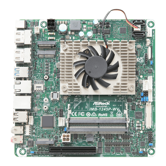
Page 10: Motherboard Layout
1.3 Motherboard Layout SATA _ DC_JACK1 PCIE_ISOLATION TO_UPS1 CPU_FAN1 4P_ATX SATA _ Bottom: Top: HDMI1 HDMI0 M2-M1 M2-E1 Bottom: Top: HDMI3 HDMI2 USB 3.2 Gen2 Top: USB3_1 Bottom: USB3_2 SIM1 LAN1 BIOS1 LAN2 TPM1 IMB-1245M-WV USB 2.0 SPEAKER1 Top: USB2_3 Bottom: USB2_4 DDR5_B1 SMB1... - Page 11 IMB-1245P-WV /IMB-1245M-WV Back M2-M2 ESPI1...
- Page 12 1 : 2-pin UPS Module Power Input Connector (TO_UPS1) 2 : M.2 Key-M Socket (M2_M1) 3 : 4-pin ATX PWR Connector (4P_ATX) 4 : M.2 Key-E Socket (M2_E1) 5 : TPM Header (TPM1) 6 : SPDIF Header (SPDIF1) 7 : PCIE_ISOLATION1 8 : SATA3 Connectors (SATA3_0, SATA3_1) 9 : CPU FAN Connector (+12V) (CPU_FAN1) 10 : SATA Power Output Connector (SATA0_PWR1)
-
Page 13: I/O Panel
IMB-1245P-WV /IMB-1245M-WV 1.4 I/O Panel DC_JACK1 Mic In (MIC1) HDMI Port (HDMI0) 10 USB 2.0 Port (USB2_4) HDMI Port (HDMI2) 11 USB 3.2 Gen2 Port (USB3_2) USB 3.2 Gen2 Port (USB3_1) 12 HDMI Port (HDMI3) RJ45 LAN Port (LAN1)* 13 HDMI Port (HDMI1) RJ45 LAN Port (LAN2)** USB 2.0 Port (USB2_3) -
Page 14: Block Diagram
1.5 Block Diagram IMB-1245-WV CSI-2 22-pin MIPI PCIe x8 Gen5 PCIe x8 Connector Channel A DDR5 SO-DIMM 5600MHZ LVDS CH7513A DDIA Support connector Channel B DDR5 eDP bypass SO-DIMM 5600MHZ HDMI DDIB connector SATA x2 SATA Port x2 HDMI TCP0 PCIe Gen4 x1 connector USB 2.0... -
Page 15: Chapter 2 Installation
IMB-1245P-WV /IMB-1245M-WV Chapter 2 Installation This is a Mini-ITX (6.7-in x 6.7-in x 0.97-in, 17.0 cm x 17.0 cm x 2.48 cm) form factor moth- erboard. Before you install the motherboard, study the configuration of your chassis to ensure that the motherboard fits into it. -
Page 16: Installation Of Memory Modules
2.3 Installation of Memory Modules IMB-1245P-WV / IMB-1245M-WV provides two 262-pin DDR5 (Double Data Rate 5) SO- DIMM slots, and supports Dual Channel Memory Technology. The SO-DIMM only fits in one correct orientation. It will cause permanent damage to the motherboard and the SO-DIMM if you force the SO-DIMM into the slot at incor- rect orientation. -
Page 17: Expansion Slots
IMB-1245P-WV /IMB-1245M-WV 2.4 Expansion Slots There are one PCI Express slot, four M.2 sockets, and one SIM socket on IMB-1245P-WV / IMB-1245M-WV. PCIE slot: 1 x PCIE (PCIE 5.0 x8 slot) is used for PCI Express x8 lane width cards. - Page 18 M.2 Key-E Socket (M2_E1) M.2 Key-B Socket (M2_B1) Signal Name Signal Name Signal Name Signal Name +3.3V +3.3V USB_D+ +3.3V +3.3V USB_D- FuLL_Card_ Power_off 9 CNV_WGR_D1- CNV_RF_RESET 10 USB_D+ DISABLE1_N 11 CNV_WGR_D1+ USB_D- MODEM_ CLKREQ 15 CNV_WGR_D0- 17 CNV_WGR_D0+ CNV_WGR_ DISABLE2_N CNV_BRI_RSP CLK-...
-
Page 19: Jumpers Setup
IMB-1245P-WV /IMB-1245M-WV 2.5 Jumpers Setup The illustration shows how jumpers are setup. When the jumper cap is placed on pins, the jumper is “Short.” If no jumper cap is placed on pins, the jumper is “Open. ” The illustration shows a 3-pin jumper whose pin1 and pin2 are “Short”... - Page 20 DACC Jumper Setting Description Open No ACC (2-pin DACC1) Short ACC (Default) (see p. 4, No. 24) Auto clear CMOS when system boot improperly. Chassis Intrusion Headers (2-pin CI1) Setting Description Open Normal (Default) (see p. 4, No. 26) Short Active Case Open (2-pin CI2) Setting...
- Page 21 IMB-1245P-WV /IMB-1245M-WV Clear CMOS Header Setting Description Normal (Default) (3-pin CLRMOS1) Clear CMOS (see p. 4, No. 34) NOTE: CLRMOS1 allows you to clear the data in CMOS. To clear and reset the system parameters to default setup, please turn off the computer and unplug the power cord from the power supply.
-
Page 22: Onboard Headers And Connectors
2.6 Onboard Headers and Connectors Onboard headers and connectors are NOT jumpers. Do NOT place jumper caps over these headers and connectors. Placing jumper caps over the headers and connectors will cause per- manent damage to the motherboard! 2-pin UPS Module Power Input Connector Signal Name (2-pin TO_UPS1) DC Input... - Page 23 IMB-1245P-WV /IMB-1245M-WV PCIE_ISOLATION1 Signal Name PSON# (2-pin PCIE_ISOLATION1) (see p. 4, No. 7) Connect to PCIE_ISOLATION_1 header on VGA-PWR card. SATA3 Connectors Signal Name SATA3_0 (7-pin SATA3_0, SATA3_1) SATA-A+ (see p. 4, No. 8) SATA-A- SATA3_1 SATA-B- SATA-B+ The Serial ATA3 (SATA3) connector supports SATA data cables for internal storage de- vices.
- Page 24 Battery Connector Signal Name +BAT (BAT1) (see p. 4, No. 11) MIPI Connector Signal Name (22-pin MIPI1) I2C0_SDA (see p. 4, No. 12) I2C0_SCL CSI_E_D3_DP CSI_E_D3_DN CSI_E_D2_DP CSI_E_D2_DN CSI_E_CK_DP CSI_E_CK_DN CSI_E_D1_DP CSI_E_D1_DN CSI_E_D0_DP CSI_E_D0_DN JCTL1 (Default 1-2) Signal Name REMOTE_CTL_ATX (3-pin JCTL1) REMOTE_CTL (see p.
- Page 25 IMB-1245P-WV /IMB-1245M-WV Power Adapter Signal Name (4-pin JPWR_ADAPTER1) 5VA_CONTROL (see p. 4, No. 16) Backlight Volume Control Signal Name GPIO_VOL_UP (7-pin BLT_VOL1) GPIO_VOL_DW (see p. 4, No. 17) PWRDN BLT_UP BLT_DW Inverter Power Control Wafer Signal Name (6-pin BLT_PWR1) (see p. 4, No. 18)
- Page 26 System Panel Header Signal Name Signal Name HDLED+ PLED+ (9-pin PANEL1) HDLED- PLED- (see p. 4, No. 23) PWRBTN# RESET# This header accommodates several system front panel functions. Connect the power switch, reset switch and system status indicator on the chassis to this header according to the pin assignments below.
- Page 27 IMB-1245P-WV /IMB-1245M-WV * This motherboard supports RS232/422/485 on COM3~5 ports. Please refer to the table below for the pin definition. In addition, COM3~5 ports (RS232/422/485) can be adjusted in BIOS setup utility > Advanced Screen > Super IO Configuration. You may refer to our user manual for details.
- Page 28 3W Audio AMP Output Wafer Signal Name OUTLN (4-pin SPEAKER1) OUTLP (see p. 4, No. 35) OUTRP OUTRN Front Panel Audio Header Signal Name Signal Name MIC2_L (9-pin HD_AUDIO1) MIC2_R (see p. 4, No. 36) OUT2_R MIC_RET J_SENSE OUT2_L OUT_RET This is line out/microphone interface for front panel audio cable that allows jack detection, convenient connection and control of audio devices.
-
Page 29: Chapter 3 Uefi Setup Utility
Chapter 3 UEFI SETUP UTILITY 3.1 Introduction ASRock Industrial UEFI (Unified Extensible Firmware Interface) is a BIOS utility which offers tweak-friendly options in an advanced viewing interface. This BIOS utility can perform the Power-On Self-Test (POST) during system startup, re- cord hardware parameters of the system, load operating system, and so on. -
Page 30: Uefi Menu Bar
3.1.2 UEFI Menu Bar The top of the screen has a menu bar with the following selections: Main For setting system time/date information For advanced system configurations Advanced H/W Monitor Displays current hardware status Security For security settings Boot For configuring boot settings and boot priority Exit Exit the current screen or the UEFI Setup Utility Because the UEFI software is constantly being updated, the following UEFI setup... -
Page 31: Navigation Keys
IMB-1245P-WV /IMB-1245M-WV 3.1.3 Navigation Keys Use < > key or < > key to choose among the selections on the menu bar, and use < > key or < > key to move the cursor up or down to select items, then press <Enter>... -
Page 32: Main Screen
3.2 Main Screen When you enter the UEFI Setup Utility, the Main screen will appear and display the system overview. Because the UEFI software is constantly being updated, the following UEFI setup screens and descriptions are for reference purpose only, and they may not exactly match what you see on your screen. -
Page 33: Advanced Screen
IMB-1245P-WV /IMB-1245M-WV 3.3 Advanced Screen I n t h i s s ec t ion, you may s et t he con f ig u r at ions for t he fol low i ng items: CPU Configuration, Chipset Configuration, Storage Configuration, Super IO Configuration,... -
Page 34: Cpu Configuration
3.3.1 CPU Configuration Intel Hyper Threading Technology Intel Hyper Threading Technology allows multiple threads to run on each core, so that the overall performance on threaded software is improved. Configuration options: [Enabled] [Disabled] Active Processor P-Cores This allows you to select the number of cores to enable in each processor package. Active Processor E-Cores This allows you to select the number of E-Cores to enable in each processor package. - Page 35 IMB-1245P-WV /IMB-1245M-WV Package C State Support The option allows you to enable CPU, PCIe, Memory, Graphics C State Support forpower saving. CFG Lock The option allows you to enable or disable the CFG Lock. Configuration options: [Enabled] [Disabled] Intel Virtualization Technology...
-
Page 36: Chipset Configuration
3.3.2 Chipset Configuration Primary Graphics Adapter The option allows you to select a primary VGA. Configuration options: [Onboard] [PCI Express] (Options vary when you have installed a graphics card on your motherboard.) - Page 37 IMB-1245P-WV /IMB-1245M-WV Above 4G Decoding The option allows you to enable or disable above 4G Memory Mapped IO decoding. This is disabled automatically when Aperture Size is set to 2048MB. Configuration options: [Enabled] [Disabled] VT-d Intel® Virtualization Technology for Directed I/O helps your virtual machine monitor bet- ter utilize hardware by improving application compatibility and reliability, and providing additional levels of manageability, security, isolation, and I/O performance.
- Page 38 Render Standby Power down the render unit when the GPU is idle for lower power consumption. Maximum Memory Frequency Maximum Memory Frequency Selections in MHz. Active LVDS Active LVDS Use this option to enable or disable the LVDS. The default value is [Disabled]. Set the item to [Enabled].
- Page 39 IMB-1245P-WV /IMB-1245M-WV Deep S5 Mobile platforms support Deep S5 in DC only and desktop platforms support Deep S5 in AC only. The default value is [Disabled]. Configuration options: [Auto] [Disabled] Restore on AC/Power Loss The option allows you to select the power state after a power failure.
-
Page 40: Storage Configuration
3.3.3 Storage Configuration VMD Configuration This item allows you to enable or disable the Intel VMD support function. SATA Controller(s) The option allows you to enable or disable the SATA controllers. Configuration options: [Enabled] [Disabled] SATA Mode Selection AHCI supports new features that improve performance. Configuration option: [AHCI] SATA Aggressive Link Power Management SATA Aggressive Link Power Management allows SATA devices to enter a low power state... -
Page 41: Super Io Configuration
IMB-1245P-WV /IMB-1245M-WV 3.3.4 Super IO Configuration COM3 Configuration Use this to set parameters of COM3. Type Select Use this to select COM3 port type: [RS232], [RS422] or [RS485]. COM4 Configuration Use this to set parameters of COM4. Type Select Use this to select COM4 port type: [RS232], [RS422] or [RS485]. -
Page 42: Amt Configuration
3.3.5 AMT Configuration USB Provisioning of AMT Use this to enable or disable AMT USB Provisioning. The default is [Disabled]. MAC Pass Through The option enables or disables MAC Pass Through function. Dynamic Lan Switch This allows switching AMT support from Integrated LAN to Discrete LAN. Activate Remote Assistance Process Trigger CIRA boot. - Page 43 IMB-1245P-WV /IMB-1245M-WV One Click Recovery(OCR) Configuration Configuration setting for One Click Recovery. This allows access for AMT to boot a recov- ery OS application MEBx This Formset contains forms for configuring MEBx.
-
Page 44: Acpi Configuration
3.3.6 ACPI Configuration PCIE Devices Power On Use this item to enable or disable PCIE devices to turn on the system from the power-soft- off mode. RTC Alarm Power On RTC Alarm Power On allows the system to be waked up by the real time clock alarm. Set it to By OS to let it be handled by your operating system. -
Page 45: Usb Configuration
IMB-1245P-WV /IMB-1245M-WV 3.3.7 USB Configuration USB Power Control Use this option to control USB power. M.2 Key_B USB Function The item enables or disables M.2 Key_B USB function. -
Page 46: Trusted Computing
3.3.8 Trusted Computing NOTE: Options vary depending on the version of your connected TPM module. Security Device Support Security Device Support allows you to enable or disable BIOS support for security device. O.S. will not show Security Device. TCG EFI protocol and INT1A interface will not be available. - Page 47 IMB-1245P-WV /IMB-1245M-WV SM3_256 PCR Bank SM3_256 PCR Bank allows you to enable or disable SM3_256 PCR Bank. Configuration options: [Enabled] [Disabled] Pending Operation Pending Operation allows you to schedule an Operation for the Security Device. NOTE: Your computer will reboot during restart in order to change State of the Device.
-
Page 48: Hardware Health Event Monitoring Screen
3.4 Hardware Health Event Monitoring Screen This section allows you to monitor the status of the hardware on your system, including the parameters of the CPU temperature, motherboard temperature, CPU fan speed, and the critical voltage. NOTE: Options vary depending on the features of your motherboard. CPU_Fan 1 Setting This item allows you to select a fan mode for CPU Fan 1. -
Page 49: Security Screen
IMB-1245P-WV /IMB-1245M-WV 3.5 Security Screen In this section you may set or change the supervisor/user password for the system. You may also clear the user password. Supervisor Password Set or change the password for the administrator account. Only the administrator has the authority to change the settings in the UEFI Setup Utility. -
Page 50: Boot Screen
3.6 Boot Screen This section displays the available devices on your system for you to configure the boot settings and the boot priority. Boot From Onboard LAN The item allows the system to be waked up by the onboard LAN. Configuration options: [Enabled] [Disabled] Setup Prompt Timeout The item allows you to... -
Page 51: Exit Screen
IMB-1245P-WV /IMB-1245M-WV 3.7 Exit Screen Save Changes and Exit When you select this option, the following message “Save configuration changes and exit setup?” will pop out. Select [Yes] to save the changes and exit the UEFI SETUP UTILITY. Discard Changes and Exit When you select this option, the following message “Discard changes and exit setup?”...
Need help?
Do you have a question about the IMB-1245P-WV and is the answer not in the manual?
Questions and answers