
Subscribe to Our Youtube Channel
Related Manuals for ASRock Industrial IMB-1239-WV


Summary of Contents for ASRock Industrial IMB-1239-WV
- Page 1 IMB-1239-WV IMB-1240-WV IMB-X1240-WV User Manual Version 1.1 Updated October 26, 2023 Copyright©2023 ASRockInd INC. All rights reserved.
- Page 2 Version 1.0 Published October, 2023 Copyright©2023 ASRockInd INC. All rights reserved. Copyright Notice: No part of this documentation may be reproduced, transcribed, transmitted, or translated in any language, in any form or by any means, except duplication of documentation by the purchaser for backup purpose, without written consent of ASRockInd Inc.
- Page 3 WARNING THIS PRODUCT CONTAINS A BUTTOON BATTERY If swallowed, a button battery can cause serious injury or death. Please keep batteries out of sight or reach of children. CALIFORNIA, USA ONLY The Lithium battery adopted on this motherboard contains Perchlorate, a toxic substance controlled in Perchlorate Best Management Practices (BMP) regulations passed by the California Legislature.
- Page 4 Contents Chapter 1 Introduction Package Contents Specifications Motherboard Layout I/O Panel Block Diagram Chapter 2 Installation Screw Holes Pre-installation Precautions Installation of Memory Modules Expansion Slots Jumpers Setup Onboard Headers and Connectors Chapter 3 UEFI SETUP UTILITY Introduction 3.1.1 Entering BIOS Setup 3.1.2 UEFI Menu Bar 3.1.3...
- Page 5 3.3.4 Super IO Configuration 3.3.5 AMT Configuration 3.3.6 ACPI Configuration 3.3.7 USB Configuration 3.3.8 Trusted Computing Hardware Health Event Monitoring Screen Security Screen Boot Screen Exit Screen...
- Page 6 IMB-1239-WV_IMB-1240-WV_IMB-X1240-WV Chapter 1 Introduction Thank you for purchasing ASRockInd IMB-1239-WV / IMB-1240-WV / IMB-X1240-WV motherboard, a reliable motherboard produced under ASRockInd’s consistently stringent quality control. It delivers excellent performance with robust design conforming to ASRock- Ind’s commitment to quality and endurance.
- Page 7 1.2 Specifications IMB-1239-WV • Dimensions Mini-ITX (6.7-in x 6.7-in x 1.5-in, 17.0 cm x 17.0 cm Form Factor (LxWxH) x 2.5 cm) Intel® 14th/13th/12th Gen (Raptor Lake-S Refresh/ Raptor Lake-S/Alder Lake-S) Core™ Processors, up Processor to 65W System Chipset Intel® H610...
- Page 8 IMB-1239-WV_IMB-1240-WV_IMB-X1240-WV HDMI 2 x HDMI 2.0b DisplayPort 1 x DP 1.4a++ 1 x 2.5 Gigabit LAN Ethernet Rear I/O 1 x 1 Gigabit LAN 2 x USB 3.2 (Gen2) 2 x USB 2.0 Audio 2 (Mic-in, Line-out) 1 x USB 3.2 Gen1 (1 x USB 3.2 header) 3 x USB 2.0 (1 x 2.54 pitch header) COM1, COM3 (RS-232/422/485) GPIO...
- Page 9 IMB-1240-WV • Dimensions Mini-ITX (6.7-in x 6.7-in x 1.5-in, 17.0 cm x 17.0 cm Form Factor (LxWxH) x 2.5 cm Intel® 14th/13th/12th Gen (Raptor Lake-S Refresh/ Raptor Lake-S/Alder Lake-S) Core™ Processors, up Processor to 65W System Chipset Intel® Q670 Socket LGA1700 BIOS AMI SPI 256 Mbit...
- Page 10 IMB-1239-WV_IMB-1240-WV_IMB-X1240-WV LAN1: Intel® I226V with 10/100/1000/2500 Mbps Controller/ LAN2: Intel® I219LM with 10/100/1000 Mbps, Ethernet Speed supports vPro Controller 2 x RJ-45 HDMI 2 x HDMI 2.0b DisplayPort 1 x DP 1.4a++ 1 x 2.5 Gigabit LAN Rear I/O Ethernet 1 x 1 Gigabit LAN 4 x USB 3.2 (Gen2) Audio...
- Page 11 12~28V DC-In with 4-pin wafer PWR cable or DC Input PWR Jack (Screw type) Power AT/ATX Supported Requirements - AT : Directly PWR on as power input ready Power On - ATX : Press button to PWR on after power input ready Operating 0ºC ~ 70ºC...
- Page 12 IMB-1239-WV_IMB-1240-WV_IMB-X1240-WV IMB-X1240-WV • Dimensions Mini-ITX (6.7-in x 6.7-in x 1.5-in, 17.0 cm x 17.0 cm Form Factor (LxWxH) x 2.5 cm) Intel® 14th/13th/12th Gen (Raptor Lake-S Refresh/ Raptor Lake-S/Alder Lake-S) Core™ Processors, up Processor to 65W System Chipset Intel® W680 Socket LGA1700 BIOS...
- Page 13 LAN1: Intel® I226V with 10/100/1000/2500 Mbps Controller/ LAN2: Intel® I219LM with 10/100/1000 Mbps, Ethernet Speed supports vPro Controller 2 x RJ-45 HDMI 2 x HDMI 2.0b DisplayPort 1 x DP 1.4a++ 1 x 2.5 Gigabit LAN Rear I/O Ethernet 1 x 1 Gigabit LAN 4 x USB 3.2 (Gen2) Audio 2 (Mic-in, Line-out)
- Page 14 IMB-1239-WV_IMB-1240-WV_IMB-X1240-WV 12~28V DC-In with 4-pin wafer PWR cable or Input PWR DC Jack (Screw type) Power AT/ATX Supported Requirements - AT : Directly PWR on as power input ready Power On - ATX : Press button to PWR on after power input ready Operating 0ºC ~ 70ºC...
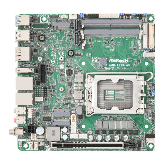
- Page 15 1.3 Motherboard Layout IMB-1239-WV • PWR_COM1 HEATER1 BKT_PWR1 DACC1 JGPIO_SET1 JGPIO1 COM3 COM1 ESPI1 BAT1 USB 3.2 Gen2 SATA_PWR1 JGPIO_PWR1 T: USB3_2 B: USB3_1 DDR _A1 M2_B1 DDR _B1 USB 2.0 16 (*Backside: EDP1) T: USB3_8 B: USB3_7 PNL_PWR1 EDP_BLT_PWR2...
- Page 16 IMB-1239-WV_IMB-1240-WV_IMB-X1240-WV 1 : ESPI Header (ESPI1) 2 : M.2 Key-B Socket (M2_B1) 3 : Battery Connector (BAT1) 4 : SATA Power Output Connector (SATA_PWR1) 5 : SATA3 Connectors (SATA3_5, SATA3_6) 6 : Digital Input/Output Power Select (JGPIO_PWR1) 7 : Digital Input/Output Default Value Setting (JGPIO_SET1) 8 : Digital Input/Output Pin Header (JGPIO1) 9 : COM Port Headers (COM1, COM3) (RS232/422/485) 10 : COM Port PWR Setting Jumpers PWR_COM1 (For COM Port1)
- Page 17 IMB-1240-WV / IMB-X1240-WV • PWR_COM1 HEATER1 BKT_PWR1 DACC1 ESPI1 JGPIO_SET1 JGPIO1 COM3 COM1 USB 3.2 Gen2 BAT1 SATA_PWR1 JGPIO_PWR1 T: USB3_2 B: USB3_1 DDR _A1 M2_B1 M2_KEYM2 DDR _B1 USB 3.2 Gen2 17 (*Backside: EDP1) T: USB3_8 B: USB3_7 PNL_PWR1 EDP_BLT_PWR2 Industrial USB3_4_9...
- Page 18 IMB-1239-WV_IMB-1240-WV_IMB-X1240-WV 1 : M.2 Key-M Socket (M2_KEYM2) 2 : ESPI Header (ESPI1) 3 : M.2 Key-B Socket (M2_B1) 4 : Battery Connector (BAT1) 5 : SATA Power Output Connector (SATA_PWR1) 6 : SATA3 Connectors (SATA3_5, SATA3_6) 7 : Digital Input/Output Power Select (JGPIO_PWR1) 8 : Digital Input/Output Default Value Setting (JGPIO_SET1) 9 : Digital Input/Output Pin Header (JGPIO1) 10 : COM Port Headers (COM1, COM3) (RS232/422/485)
- Page 19 1.4 I/O Panel IMB-1239-WV • IMB-1240-WV / IMB-X1240-WV • USB 3.2 Gen2 Ports (USB3_1_2) HDMI Port (HDMI1) Top: USB3_2 DisplayPort (DP1) Bottom: USB3_1 HDMI Port (HDMI2) IMB-1239-WV: RJ45 LAN Port (LAN2)** USB 2.0 Ports (USB3_7_8) RJ45 LAN Port (LAN1)* IMB-1240-WV / IMB-X1240-WV: Audio Output: Green - Line Out USB 3.2 Gen2 (USB3_7_8)
- Page 20 IMB-1239-WV_IMB-1240-WV_IMB-X1240-WV * There are two LED next to the LAN1 port. Please refer to the table below for the LAN1 port LED indica- tions. LAN1 Port LED Indications ACT/LINK SPEED Activity/Link LED SPEED LED Status Description Status Description No Link 10Mbps connection Blinking Data Activity...
- Page 21 1.5 Block Diagram IMB-1239-WV • IMB-1239-WV Connector SO-DIMM HDMI HDMI Channel A DDR5 Intel (A1) 4800/5600MHz Connector IT66318 Alder Lake-S & SO-DIMM Channel B DDR5 Display port Raptor Lake-S & Raptor 4800/5600MHz (B1) Connector Lake-S Refresh Processor PCIe Gen5 [0:15]...
- Page 22 IMB-1239-WV_IMB-1240-WV_IMB-X1240-WV IMB-1240-WV / IMB-X1240-WV • IMB-X1240_1240-WV Connector SO-DIMM HDMI HDMI Channel A DDR5 Intel (A1) 4800/5600MHz Connector IT66318 Alder Lake-S & SO-DIMM Channel B DDR5 Display port Raptor Lake-S & Raptor 4800/5600MHz (B1) Connector Lake-S Refresh Processor PCIe x16 or PCIe Gen5 [0:15] LGA-1700 HDMI...
- Page 23 Chapter 2 Installation This is a Mini-ITX (6.7-in x 6.7-in x 1.5-in, 17.0 cm x 17.0 cm x 2.5 cm) form factor mother- board. Before you install the motherboard, study the configuration of your chassis to ensure that the motherboard fits into it. Make sure to unplug the power cord before installing or removing the motherboard.
- Page 24 IMB-1239-WV_IMB-1240-WV_IMB-X1240-WV 2.3 Installation of Memory Modules IMB-1239-WV / IMB-1240-WV provides two 262-pin DDR5 (Double Data Rate 5) SO- DIMM slots, and supports Dual Channel Memory Technology. IMB-X1240-WV provides two 262-pin DDR5 (Double Data Rate 5) SO-DIMM slots, and supports Dual Channel ECC/non-ECC Memory Technology.
- Page 25 2.4 Expansion Slots There are one PCI Express slot, three M.2 sockets and one SIM socket on IMB-1239-WV. There are one PCI Express slot, four M.2 sockets and one SIM socket on IMB-1240-WV / IMB-X1240-WV. PCIE slot: IMB-1239-WV: PCIE1 (PCIE 5.0 x16 slot) is used for PCI Express x16 lane width cards.
- Page 26 IMB-1239-WV_IMB-1240-WV_IMB-X1240-WV M.2 Key-B Socket (M2_B1) M.2 Key-E Socket (M2_KEYE1) Signal Name Signal Name Signal Name Signal Name +3.3V +3.3V +3.3V USB_D+ +3.3V FuLL_Card_ USB_D- Power_off USB_D+ W_DISABLE 9 CNV_WGR_D1- CNV_RF_RESET 10 USB_D- 11 CNV_WGR_D1+ MODEM_ CLKREQ 15 CNV_WGR_D0- 17 CNV_WGR_D0+ CNV_WGR_ CNV_BRI_RSP USB3_RX-...
- Page 27 M.2 Key-M Socket (M2_KEYM2) (only for IMB-1240-WV / IMB-X1240-WV) Signal Name Signal Name +3.3V +3.3V PERn3 PERp3 SATA_LED PETn3 +3.3V PETp3 +3.3V +3.3V PERn2 +3.3V PERp2 PETn2 PETp2 PERn1 PERp1 USB_D+ PETn1 USB_D- PETp1 SMB_CLK PERn0 SMB_DATA PERp0 PETn0 PETp0 PERST# CLKREQ# PEFCLKn...
- Page 28 IMB-1239-WV_IMB-1240-WV_IMB-X1240-WV 2.5 Jumpers Setup The illustration shows how jumpers are setup. When the jumper cap is placed on pins, the jumper is “Short.” If no jumper cap is placed on pins, the jumper is “Open. ” The illustration shows a 3-pin jumper whose pin1 and pin2 are “Short”...
- Page 29 Backlight Power Select (LCD_BLT_VCC) Setting Description LCD_BLT_VCC: +5V (5-pin BKT_PWR1) (Default) (see p. 10, No. 12; p. 12, No. 13) LCD_BLT_VCC: +12V LCD_BLT_VCC: DC-IN Use this header to set up the backlight power of the LVDS connector and the panel backlight power of BLT_PWM1.
- Page 30 IMB-1239-WV_IMB-1240-WV_IMB-X1240-WV BIOS. If you need to clear the CMOS when you just finish updating the BIOS, you must boot up the system first, and then shut it down before you do the clear-CMOS action. Please be noted that the password, date, and time will be cleared only if the CMOS battery is removed.
- Page 31 2.6 Onboard Headers and Connectors Onboard headers and connectors are NOT jumpers. Do NOT place jumper caps over these headers and connectors. Placing jumper caps over the headers and connectors will cause per- manent damage to the motherboard! ESPI Header Signal Name (20-pin ESPI1) ESPI_CLK...
- Page 32 IMB-1239-WV_IMB-1240-WV_IMB-X1240-WV SATA3 Connectors Signal Name SATA3_5 (7-pin SATA3_5, SATA3_6) SATA-A+ (see p. 10, No. 5; p. 12, No. 6) SATA-A- SATA3_6 SATA-B- SATA-B+ The Serial ATA3 (SATA3) connector supports SATA data cables for internal storage de- vices. The current SATA3 interface allows up to 6.0 Gb/s data transfer rate.
- Page 33 Heater Header Signal Name Heater PWR (3-pin HEATER1) (see p. 10, No. 11; p. 12, No. 12) Backlight Volume Control Signal Name GPIO_VOL_UP (7-pin BLT_VOL1) GPIO_VOL_DW (see p. 10, No. 14; p. 12, No. 15) PWRDN BLT_UP BLT_DW Inverter Power Control Wafer Signal Name (6-pin BLT_PWR1) (see p.
- Page 34 IMB-1239-WV_IMB-1240-WV_IMB-X1240-WV Inverter Power Control Wafer Signal Name (6-pin EDP_BLT_PWR2) (see p. 10, No. 18; p. 12, No. 19) eDP_LBKLT_CTL eDP_LBKLT_EN +12_FUSE +12_FUSE System Panel Header Signal Name Signal Name HDLED+ PLED+ (9-pin PANEL1) HDLED- PLED- PWRBTN# (see p. 10, No. 23; p. 12, No. 24) RESET# This header accommodates several system front panel functions.
- Page 35 CPU Fan Connector (+12V) Signal Name (4-pin CPU_FAN1) +12V (see p. 10, No. 25; p. 12, No. 26) CPU_FAN_SPEED FAN_SPEED_CONTROL The board offers three 4-pin CPU fan (Smart Fan) connectors which are compatible with 3-pin CPU fan. If you connect a 3-pin CPU fan to the CPU fan connector on this mother- board, please connect it to pin 1-3.
- Page 36 (see p. 12, No. 36) USB2_10_11 USB2_5_6 IMB-1239-WV provides one internal USB 2.0 header, while IMB-1240-WV / IMB-X1240- WV provides two internal USB 2.0 headers. The connector can support two USB 2.0 ports. The maximum current per port is 0.5A.
- Page 37 IntA_PA_SSRX- 16 Vbus Vbus There is one USB 3.2 Gen1 connector on IMB-1239-WV. This header can support one USB 3.2 Gen1 port and one USB 2.0 port, with maximum power current 0.9A per port. USB 3.2 Gen1 Connector(for IMB-1240-WV / IMB-X1240-WV)
- Page 38 IMB-1239-WV_IMB-1240-WV_IMB-X1240-WV Chapter 3 UEFI SETUP UTILITY 3.1 Introduction ASRock Industrial UEFI (Unified Extensible Firmware Interface) is a BIOS utility which offers tweak-friendly options in an advanced viewing interface. The UEFI system works with a USB mouse and offers users a faster, sleeker experience.
- Page 39 3.1.2 UEFI Menu Bar The top of the screen has a menu bar with the following selections: Main For setting system time/date information For advanced system configurations Advanced H/W Monitor Displays current hardware status Security For security settings Boot For configuring boot settings and boot priority Exit Exit the current screen or the UEFI Setup Utility Because the UEFI software is constantly being updated, the following UEFI setup...
- Page 40 IMB-1239-WV_IMB-1240-WV_IMB-X1240-WV 3.1.3 Navigation Keys Use < > key or < > key to choose among the selections on the menu bar, and use < > key or < > key to move the cursor up or down to select items, then press <Enter> to get into the sub screen.
- Page 41 3.2 Main Screen When you enter the UEFI Setup Utility, the Main screen will appear and display the system overview. IMB-1239-WV • IMB-1240-WV •...
- Page 42 IMB-1239-WV_IMB-1240-WV_IMB-X1240-WV IMB-X1240-WV • Because the UEFI software is constantly being updated, the following UEFI setup screens and descriptions are for reference purpose only, and they may not exactly match what you see on your screen. Options may also vary depending on the features of your motherboard.
- Page 43 I n t h i s s ec t ion, you may s et t he con f ig u r at ions for t he fol low i ng items: CPU Configuration, Chipset Configuration, Storage Configuration, Super IO Configuration, AMT Configuration, ACPI Configuration, USB Configuration and Trusted Computing. IMB-1239-WV • IMB-1240-WV / IMB-X1240-WV •...
- Page 44 IMB-1239-WV_IMB-1240-WV_IMB-X1240-WV Setting wrong values in this section may cause the system to malfunction. Instant Flash Instant Flash is a UEFI flash utility embedded in Flash ROM. This convenient UEFI up- date tool allows you to update system UEFI without entering operating systems first like Windows®.
- Page 45 3.3.1 CPU Configuration Intel Hyper Threading Technology Intel Hyper Threading Technology allows multiple threads to run on each core, so that the overall performance on threaded software is improved. Configuration options: [Enabled] [Disabled] Active Processor P-Cores This allows you to select the number of cores to enable in each processor package. Active Processor E-Cores This allows you to select the number of E-Cores to enable in each processor package.
- Page 46 IMB-1239-WV_IMB-1240-WV_IMB-X1240-WV Enhanced Halt State (C1E) The option allows you to enable Enhanced Halt State (C1E) for lower power consumption. Configuration options: [Enabled] [Disabled] CPU C States Support This allows you to enable CPU C States Support for power saving. It is recommended to keep C3, C6 and C7 all enabled for better power saving.
- Page 47 Intel Turbo Boost Technology Intel Turbo Boost Technology enables the processor to run above its base operating fre- quency when the operating system requests the highest performance state. The default value is [Enabled]. Configuration options: [Enabled] [Disabled] CPU Thermal Throttling CPU Thermal Throttling allows you to enable CPU internal thermal control mechanisms to keep the CPU from overheating.
- Page 48 IMB-1239-WV_IMB-1240-WV_IMB-X1240-WV 3.3.2 Chipset Configuration IMB-1239-WV • IMB-1240-WV / IMB-X1240-WV •...
- Page 49 Primary Graphics Adapter The option allows you to select a primary VGA. Configuration options: [Onboard] [PCI Express] (Options vary when you have installed a graphics card on your motherboard.) Above 4G Decoding The option allows you to enable or disable above 4G Memory Mapped IO decoding. This is disabled automatically when Aperture Size is set to 2048MB.
- Page 50 IMB-1239-WV_IMB-1240-WV_IMB-X1240-WV ed graphics processor when the system boots up. C o n f i g u r a t i o n o p t i o n s : [ A u t o ] [3 2 M ] [6 4 M ] [1 2 8 M ] [2 5 6 M ] [51 2 M ] Options vary depending on the memory you use on your motherboard.
- Page 51 3.3.3 Storage Configuration IMB-1239-WV • IMB-1240-WV / IMB-X1240-WV •...
- Page 52 IMB-1239-WV_IMB-1240-WV_IMB-X1240-WV VMD Configuration This item allows you to enable or disable the Intel VMD support function. SATA Controller(s) The option allows you to enable or disable the SATA controllers. Configuration options: [Enabled] [Disabled] SATA Mode Selection AHCI supports new features that improve performance. Configuration option: [AHCI] Hybrid Storage Detection and Configuration Mode The option allows you to select Hybrid Storage Detection and Configuration Mode.
- Page 53 3.3.4 Super IO Configuration COM1 Configuration Use this to set parameters of COM1. Type Select Use this to select COM1 port type: [RS232], [RS422] or [RS485]. COM3 Configuration Use this to set parameters of COM3. Type Select Use this to select COM3 port type: [RS232], [RS422] or [RS485]. WDT Timeout Reset Use this to set the Watch Dog Timer.
- Page 54 IMB-1239-WV_IMB-1240-WV_IMB-X1240-WV 3.3.5 AMT Configuration USB Provisioning of AMT Use this to enable or disable AMT USB Provisioning. The default is [Disabled]. MAC Pass Through The option enables or disables MAC Pass Through function. Dynamic Lan Switch The option allows switching AMT support from Integrated LAN to Discrete LAN. Activate Remote Assistance Process Trigger CIRA boot.
- Page 55 One Click Recovery(OCR) Configuration Configuration setting for One Click Recovery. This allows access for AMT to boot a recovery OS application MEBx This Formset contains forms for configuring MEBx. PET Progress User can enable or disable PET Events progress to receive PET events or not. The default is [Enabled].
- Page 56 IMB-1239-WV_IMB-1240-WV_IMB-X1240-WV Secure Erase mode Change Secure Erase module behavior: Simulated: Performs SE flow without erasing SSD. Real: Erase SSD. Force Secure Erase Use this to enable or disable Force Secure Erase on next boot. The default is [Disabled].
- Page 57 OCR Https Boot Use the item to enable or disable One Click Recovery Https Boot. OCR PBA Boot Use the item to enable or disable One Click Recovery PBA Boot. OCR Windows Recovery Boot Use the item to enable or disable One Click Recovery Windows Recovery Boot. OCR Disable Secure Boot The item allows CSME to request SecureBoot to be disabled for One Click Recovery.
- Page 58 IMB-1239-WV_IMB-1240-WV_IMB-X1240-WV 3.3.6 ACPI Configuration Suspend to RAM Suspend to R A M a l lows you to select [Disabled] for ACPI suspend t y pe S1. It is recommended to select [Auto] for ACPI S3 power saving. Configuration options: [Auto] [Disabled] PCIE Devices Power On Use this item to enable or disable PCIE devices to turn on the system from the power-soft- off mode.
- Page 59 3.3.7 USB Configuration USB Power Control Use this option to control USB power. M.2 Key_B USB Function The item enables or disables M.2 Key_B USB function.
- Page 60 IMB-1239-WV_IMB-1240-WV_IMB-X1240-WV 3.3.8 Trusted Computing NOTE: Options vary depending on the version of your connected TPM module. Security Device Support Security Device Support allows you to enable or disable BIOS support for security device. O.S. will not show Security Device. TCG EFI protocol and INT1A interface will not be available.
- Page 61 Pending Operation Pending Operation allows you to schedule an Operation for the Security Device. NOTE: Your computer will reboot during restart in order to change State of the Device. Configuration options: [None] [TPM Clear] Platform Hierarchy This item allows you to enable or disable Platform Hierarchy. Configuration options: [Enabled] [Disabled] Storage Hierarchy This item allows you to enable or disable Storage Hierarchy.
- Page 62 IMB-1239-WV_IMB-1240-WV_IMB-X1240-WV 3.4 Hardware Health Event Monitoring Screen This section allows you to monitor the status of the hardware on your system, including the parameters of the CPU temperature, motherboard temperature, CPU fan speed, chassis fan speed, and the critical voltage. NOTE: Options vary depending on the features of your motherboard.
- Page 63 3.5 Security Screen In this section you may set or change the supervisor/user password for the system. You may also clear the user password. Supervisor Password Set or change the password for the administrator account. Only the administrator has the authority to change the settings in the UEFI Setup Utility.
- Page 64 IMB-1239-WV_IMB-1240-WV_IMB-X1240-WV 3.6 Boot Screen This section displays the available devices on your system for you to configure the boot settings and the boot priority. Boot From Onboard LAN The item allows the system to be waked up by the onboard LAN. Configuration options: [Enabled] [Disabled] Setup Prompt Timeout The item allows you to...
- Page 65 3.7 Exit Screen Save Changes and Exit When you select this option, the following message “Save configuration changes and exit setup?” will pop out. Select [Yes] to save the changes and exit the UEFI SETUP UTILITY. Discard Changes and Exit When you select this option, the following message “Discard changes and exit setup?”...
Need help?
Do you have a question about the IMB-1239-WV and is the answer not in the manual?
Questions and answers