
Subscribe to Our Youtube Channel
Related Manuals for ASRock Industrial IMB-1241


Summary of Contents for ASRock Industrial IMB-1241
- Page 1 IMB-1241 User Manual Version 1.0 Published February 23, 2024 Copyright©2024 ASRockInd INC. All rights reserved.
- Page 2 Version 1.0 Published February, 2024 Copyright©2024 ASRockInd INC. All rights reserved. Copyright Notice: No part of this documentation may be reproduced, transcribed, transmitted, or translated in any language, in any form or by any means, except duplication of documentation by the purchaser for backup purpose, without written consent of ASRockInd Inc.
- Page 3 WARNING THIS PRODUCT CONTAINS A BUTTON BATTERY If swallowed, a button battery can cause serious injury or death. Please keep batteries out of sight or reach of children. CALIFORNIA, USA ONLY The Lithium battery adopted on this motherboard contains Perchlorate, a toxic substance controlled in Perchlorate Best Management Practices (BMP) regulations passed by the California Legislature.
- Page 4 *15G062470000AK* P/N: 15G062470000AK V1.0 Button Battery Safety Notice Button Battery Safety Notice WARNING • INGESTION HAZARD: This product contains a button cell or coin battery. • DEATH or serious injury can occur if ingested. • A swallowed button cell or coin battery can cause Internal Chemical Burns in as little as 2 hours.
-
Page 5: Table Of Contents
Contents Chapter 1 Introduction Package Contents Specifications Motherboard Layout I/O Panel Block Diagram Chapter 2 Installation Screw Holes Pre-installation Precautions Installation of Memory Modules Expansion Slots Jumpers Setup Onboard Headers and Connectors Chapter 3 UEFI SETUP UTILITY Introduction 3.1.1 Entering BIOS Setup 3.1.2 UEFI Menu Bar 3.1.3... - Page 6 3.3.4 Super IO Configuration 3.3.5 ACPI Configuration 3.3.6 USB Configuration 3.3.7 Trusted Computing Hardware Health Event Monitoring Screen Security Screen Boot Screen Exit Screen...
-
Page 7: Chapter 1 Introduction
If you require technical support related to this motherboard, please visit our website for specific information about the model you are using. https://www.asrockind.com/technical-support 1.1 Package Contents ASRockInd IMB-1241 Motherboard (Mini-ITX (6.7-in x 6.7-in x 1.4-in, 17.0 cm x 17.0 cm x 3.6 cm)) -
Page 8: Specifications
1.2 Specifications Dimensions Mini-ITX (6.7-in x 6.7-in x 1.4-in, 17.0 cm x 17.0 cm Form Factor (LxWxH) x 3.6 cm) Intel® 14 Gen (Raptor Lake-S Refresh/ Raptor Lake-S/Alder Lake-S) Core™ Processors, up Processor to 65W System Chipset Intel® H610 Socket LGA1700 BIOS AMI SPI 256 Mbit... - Page 9 IMB-1241 4 x USB 2.0 (2 x 2.54 pitch header) COM5 (RS-232) Internal GPIO 4 x GPI, 4 x GPO Connector LVDS 1 (Connector share with eDP) Speaker Header 1 x M.2 (Key M, 2242/2280) with PCIe Gen3 x4 Storage or SATA3 and USB 2.0...
-
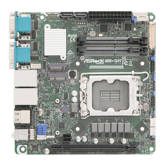
Page 10: Motherboard Layout
SATA3_4 SATA3_5 BLT_PWR1 LVDS1 ATXPWR1 BLT_PWM1 BKT_PWR1 COM6 COM1 DDR4_B1 PNL_PWR1 DDR4_A1 COM4 COM3 BLT_PWM2 Industrial COM5 IMB-1241 M2_M1 JGPIO1 BIOS M2_E1 JGPIO_SET1 USB 3.2 Gen2 JGPIO_PWR1 Top: USB3_2 LAN2 Bottom: USB3_1 PWR_BAT1_SIO_AT1 CLRMOS1 USB 3.2 Gen1 Top: USB3_4 LAN1... - Page 11 IMB-1241 1 : COM Port Header (COM5) (RS232) 2 : M.2 Key-E Socket (M2_E1) 3 : M.2 Key-M Socket (M2_M1) 4 : ESPI Header (ESPI1) 5 : SATA3 Connectors (SATA3_4, SATA3_5) 6 : Battery Connector (BAT1) 7 : 24-pin ATX Power Input Connector (ATXPWR1)
-
Page 12: I/O Panel
1.4 I/O Panel COM Port (COM1) (RS232/422/485)* Audio Output: Pink - Mic In COM Port (COM3) (RS232) HDMI Port (HDMI1) RJ45 LAN Port (LAN2)** USB 3.2 Gen1 Ports (USB3_3_4) RJ45 LAN Port (LAN1)*** 10 USB 3.2 Gen2 Ports (USB3_1_2) HDMI Port (HDMI2) 11 COM Port (COM4) (RS232) Audio Output: Green - Line Out 12 COM Port (COM6) (RS232) - Page 13 IMB-1241 ** There are two LED next to the LAN2 port. Please refer to the table below for the LAN2 port LED indica- tions. LAN2 Port LED Indications ACT/LINK SPEED Activity/Link LED SPEED LED Status Description Status Description No Link...
-
Page 14: Block Diagram
1.5 Block Diagram IMB-1241 LVDS/ Channel A DDR4 3200MHz SO-DIMM LVDS/eDP Chrontel DDIA eDP Bypass (A1) CH7513A Intel mode Alder Lake-S HDMI 2.0b DDIB HDMI Channel B DDR4 3200MHz SO-DIMM Connector (A2) Raptor Lake-S Raptor Lake-S Refresh HDMI 2.0b DDIC... -
Page 15: Chapter 2 Installation
IMB-1241 Chapter 2 Installation This is a Mini-ITX (6.7-in x 6.7-in x 1.4-in, 17.0 cm x 17.0 cm x 3.6 cm) form factor mother- board. Before you install the motherboard, study the configuration of your chassis to ensure that the motherboard fits into it. -
Page 16: Installation Of Memory Modules
2.3 Installation of Memory Modules IMB-1241 provides two 260-pin DDR4 (Double Data Rate 4) SO-DIMM slots, and supports Dual Channel Memory Technology. The SO-DIMM only fits in one correct orientation. It will cause permanent damage to the motherboard and the SO-DIMM if you force the SO-DIMM into the slot at incor- rect orientation. - Page 17 IMB-1241 Open the DIMM slot latches. Aligh the notch. Carefully press down until the DIMM slides into the slot. The latches snap back into place.
-
Page 18: Expansion Slots
2.4 Expansion Slots There are one PCI Express slot and two M.2 sockets on IMB-1241. PCIE slot: 1 x PCIE (PCIE 4.0 x16 slot) is used for PCI Express x16 lane width cards. Gen3 M.2 sockets: 1 x M.2 (Key E, 2230) with PCIe x1, USB 2.0 and CNVi for Wireless... -
Page 19: Jumpers Setup
IMB-1241 2.5 Jumpers Setup The illustration shows how jumpers are setup. When the jumper cap is placed on pins, the jumper is “Short.” If no jumper cap is placed on pins, the jumper is “Open. ” The illustration shows a 3-pin jumper whose pin1 and pin2 are “Short”... - Page 20 Digital Input/Output Default Value Setting Setting Description Pull-High (+3V) (Default) (3-pin JGPIO_SET1) Pull-Low (GND) (see p. 4, No. 16) The header is used for GPIO default value setting for either pull high or pull low. Pulling the header to a high/low value means the voltage is anchored to VCC/GND, in a stable, non- floating state.
- Page 21 IMB-1241 DACC1_PCIE_PWR1 Setting Description Open : No ACC (Default) (4-pin DACC1_PCIE_PWR1) Short : ACC PSON# (see p. 4, No. 21) DACC : Auto clear CMOS when system boot improperly. Chassis Intrusion Headers Setting Description Open: Normal (4-pin CI1_2) Short: Active Case Open Open: Active Case Open (see p.
-
Page 22: Onboard Headers And Connectors
2.6 Onboard Headers and Connectors Onboard headers and connectors are NOT jumpers. Do NOT place jumper caps over these headers and connectors. Placing jumper caps over the headers and connectors will cause per- manent damage to the motherboard! COM Port Header (RS232) Signal Name Signal Name DDCD#... - Page 23 IMB-1241 Battery Connector Signal Name +BAT (BAT1) (see p. 4, No. 6) 24-pin ATX Power Input Connector Signal Name Signal Name (24-pin ATXPWR1) -12V (see p. 4, No. 7) PSON# PWROK_PS ATX+5VSB +12V +12V This motherboard provides a 24-pin ATX power connector. To use a 20-pin ATX power supply, please plug it along Pin 1 and Pin 13.
- Page 24 LVDS Panel Connector Signal Name Signal Name LCD_VCC LCD_VCC (40-pin LVDS1) +3.3V eDP_LED_DRIVER LVDS_A_DATA0# (see p. 4, No. 12) LVDS_A_DATA0 PD (Panel Detection)* LVDS_A_DATA1# LVDS_A_DATA1 LVDS_A_DATA2# LVDS_A_DATA2 LVDS_A_DATA3# LVDS_A_DATA3 LVDS_A_CLK# LVDS_A_CLK LVDS_B_DATA0# LVDS_B_DATA0 LVDS_B_DATA1# LVDS_B_DATA1 LVDS_B_DATA2# LVDS_B_DATA2 DPLVDD_EN LVDS_B_DATA3# LVDS_B_DATA3 * PD (Panel Detection): Connect this pin to LVDS Panel’s LVDS_B_CLK# LVDS_B_CLK...
- Page 25 IMB-1241 HDLED (Hard Drive Activity LED): Connect to the hard drive activity LED on the chassis front panel. The LED is on when the hard drive is reading or writing data. The front panel design may differ by chassis. A front panel module mainly consists of power switch, reset switch, power LED, hard drive activity LED, speaker and etc.
- Page 26 4-pin ATX PWR Connector Signal Name Signal Name (4-pin ATX+12V) ATX+12V ATX+12V (see p. 4, No. 26) Please connect a DC +12V power supply to this connector. SPDIF Header Signal Name (4-pin SPDIF1) (see p. 4, No. 27) SPDIF OUT SPDIF header, providing SPDIF audio output to HDMI VGA card, allows the system to connect HDMI Digital TV/projector/LCD devices.
-
Page 27: Chapter 3 Uefi Setup Utility
Chapter 3 UEFI SETUP UTILITY 3.1 Introduction ASRock Industrial UEFI (Unified Extensible Firmware Interface) is a BIOS utility which offers tweak-friendly options in an advanced viewing interface. This BIOS utility can perform the Power-On Self-Test (POST) during system startup, re- cord hardware parameters of the system, load operating system, and so on. -
Page 28: Uefi Menu Bar
3.1.2 UEFI Menu Bar The top of the screen has a menu bar with the following selections: Main For setting system time/date information For advanced system configurations Advanced H/W Monitor Displays current hardware status Security For security settings Boot For configuring boot settings and boot priority Exit Exit the current screen or the UEFI Setup Utility Because the UEFI software is constantly being updated, the following UEFI setup... -
Page 29: Navigation Keys
IMB-1241 3.1.3 Navigation Keys Use < > key or < > key to choose among the selections on the menu bar, and use < > key or < > key to move the cursor up or down to select items, then press <Enter>... -
Page 30: Main Screen
3.2 Main Screen When you enter the UEFI Setup Utility, the Main screen will appear and display the system overview. Because the UEFI software is constantly being updated, the following UEFI setup screens and descriptions are for reference purpose only, and they may not exactly match what you see on your screen. -
Page 31: Advanced Screen
IMB-1241 3.3 Advanced Screen I n t h i s s ec t ion, you may s et t he con f ig u r at ions for t he fol low i ng items: CPU Configuration, Chipset Configuration, Storage Configuration, Super IO Configuration,... -
Page 32: Cpu Configuration
3.3.1 CPU Configuration Intel Hyper Threading Technology Intel Hyper Threading Technology allows multiple threads to run on each core, so that the overall performance on threaded software is improved. Configuration options: [Enabled] [Disabled] Active Processor P-Cores This allows you to select the number of cores to enable in each processor package. CPU C States Support This allows you to enable CPU C States Support for power saving. - Page 33 IMB-1241 CFG Lock The option allows you to enable or disable the CFG Lock. Configuration options: [Enabled] [Disabled] Intel Virtualization Technology Intel Virtualization Technology allows a platform to run multiple operating systems and applications in independent partitions, so that one computer system can function as mul- tiple virtual systems.
-
Page 34: Chipset Configuration
3.3.2 Chipset Configuration Primary Graphics Adapter The option allows you to select a primary VGA. Configuration options: [Onboard] [PCI Express] (Options vary when you have installed a graphics card on your motherboard.) Above 4G Decoding The option allows you to enable or disable above 4G Memory Mapped IO decoding. This is disabled automatically when Aperture Size is set to 2048MB. - Page 35 IMB-1241 PCIE1 Link Speed The option allows you to configure PCIE1 Slot Link Speed. Auto mode is optimizing for overclocking. Configuration options: [Auto] [Gen1] [Gen2] [Gen3] [Gen4] [Gen5] (Options vary depend- ing on your motherboard.) SR-IOV Support If system has SR-IOV capable PCIe Devices, this option Enables or Disables Single Root IO Virtualization Support.
- Page 36 Onboard HD Audio Onboard HD Audio allows you to enable or disable the onboard HD audio controller. Set this item to [Auto] to enable the onboard HD and automatically disable it when a sound card is installed. Configuration options: [Enabled] [Disabled] Restore on AC/Power Loss The option allows you to select the power state after a power failure.
-
Page 37: Storage Configuration
IMB-1241 3.3.3 Storage Configuration SATA Controller(s) The option allows you to enable or disable the SATA controllers. Configuration options: [Enabled] [Disabled] SATA Mode Selection AHCI supports new features that improve performance. Configuration option: [AHCI] Hybrid Storage Detection and Configuration Mode The option allows you to select Hybrid Storage Detection and Configuration Mode. - Page 38 Hard Disk S.M.A.R.T. S.M.A.R.T stands for Self-Monitoring, Analysis, and Reporting Technology. It is a moni- toring system for computer hard disk drives to detect and report on various indicators of reliability. Configuration options: [Enabled] [Disabled]...
-
Page 39: Super Io Configuration
IMB-1241 3.3.4 Super IO Configuration COM1 Configuration Use this to set parameters of COM1. Type Select Use this to select COM1 port type: [RS232], [RS422] or [RS485]. COM3 Configuration Use this to set parameters of COM3. COM4 Configuration Use this to set parameters of COM4. -
Page 40: Acpi Configuration
3.3.5 ACPI Configuration Suspend to RAM Suspend to R A M a l lows you to select [Disabled] for ACPI suspend t y pe S1. It is recommended to select [Auto] for ACPI S3 power saving. Configuration options: [Auto] [Disabled] PCIE Devices Power On Use this item to enable or disable PCIE devices to turn on the system from the power-soft- off mode. -
Page 41: Usb Configuration
IMB-1241 3.3.6 USB Configuration USB Power Control Use this option to control USB power. -
Page 42: Trusted Computing
3.3.7 Trusted Computing NOTE: Options vary depending on the version of your connected TPM module. Security Device Support Security Device Support allows you to enable or disable BIOS support for security device. O.S. will not show Security Device. TCG EFI protocol and INT1A interface will not be available. - Page 43 IMB-1241 SM3_256 PCR Bank SM3_256 PCR Bank allows you to enable or disable SM3_256 PCR Bank. Configuration options: [Enabled] [Disabled] Pending Operation Pending Operation allows you to schedule an Operation for the Security Device. NOTE: Your computer will reboot during restart in order to change State of the Device.
-
Page 44: Hardware Health Event Monitoring Screen
3.4 Hardware Health Event Monitoring Screen This section allows you to monitor the status of the hardware on your system, including the parameters of the CPU temperature, motherboard temperature, CPU fan speed, chassis fan speed, and the critical voltage. NOTE: Options vary depending on the features of your motherboard. CPU_Fan 1 Setting This item allows you to select a fan mode for CPU Fan 1. -
Page 45: Security Screen
IMB-1241 3.5 Security Screen In this section you may set or change the supervisor/user password for the system. You may also clear the user password. Supervisor Password Set or change the password for the administrator account. Only the administrator has the authority to change the settings in the UEFI Setup Utility. -
Page 46: Boot Screen
3.6 Boot Screen This section displays the available devices on your system for you to configure the boot settings and the boot priority. Boot From Onboard LAN The item allows the system to be waked up by the onboard LAN. Configuration options: [Enabled] [Disabled] Setup Prompt Timeout The item allows you to... -
Page 47: Exit Screen
IMB-1241 3.7 Exit Screen Save Changes and Exit When you select this option, the following message “Save configuration changes and exit setup?” will pop out. Select [Yes] to save the changes and exit the UEFI SETUP UTILITY. Discard Changes and Exit When you select this option, the following message “Discard changes and exit setup?”...
Need help?
Do you have a question about the IMB-1241 and is the answer not in the manual?
Questions and answers