Vaisala WINDCAP WMT700 Series Manuals
Manuals and User Guides for Vaisala WINDCAP WMT700 Series. We have 6 Vaisala WINDCAP WMT700 Series manuals available for free PDF download: User Manual, Technical Reference, Quick Reference Manual, Technical Notes

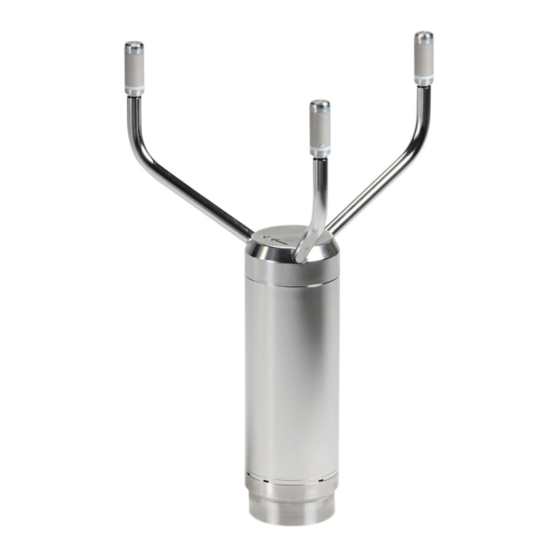
Vaisala WINDCAP WMT700 Series User Manual (221 pages)
Ultrasonic Wind Sensor
Brand: Vaisala
|
Category: Security Sensors
|
Size: 6 MB
Table of Contents
-
Safety15
-
Recycling16
-
Trademarks18
-
Warranty18
-
Heating26
-
Accessories30
-
Manual31
-
Accessories32
-
Bird Cage33
-
WM Verifier34
-
Cables35
-
Profiles48
-
Protocols49
-
Unpacking64
-
Mounting65
-
Alignment76
-
Wiring79
-
Cables79
-
Heating84
-
Powering86
-
Configuration112
-
Status Flags125
-
Operating WMT700128
-
Data Messages129
-
Missing Readings135
-
Error Indication136
-
POLL - Poll Data139
-
Frequency143
-
Voltage144
-
Missing Readings157
-
Missing Readings160
-
Missing Readings164
-
Missing Readings166
-
Profile (V 1.3)167
-
SDI-12 Commands169
-
Address Query170
-
Ad0! - Send Data174
Advertisement
Vaisala WINDCAP WMT700 Series User Manual (210 pages)
Ultrasonic Wind Sensor
Brand: Vaisala
|
Category: Accessories
|
Size: 3 MB
Table of Contents
-
Trademarks12
-
Heating22
-
Accessories27
-
Manual27
-
Accessories28
-
Bird Cage29
-
Cables30
-
Profiles42
-
Protocols43
-
Heating50
-
Installation53
-
Wiring74
-
Cables74
-
Powering78
-
Operation101
-
Configuration103
-
Status Flags115
-
Table 43 Status115
-
Operating WMT700119
-
Data Messages121
-
Missing Readings126
-
Error Indication126
-
Frequency131
-
Voltage132
-
F/G ASOS Profile137
-
Profile (V 1.3)153
-
Commands155
-
Data Messages162
-
Maintenance165
-
Troubleshooting169
-
Technical Data175

Vaisala WINDCAP WMT700 Series User Manual (136 pages)
Ultrasonic Wind Sensor
Brand: Vaisala
|
Category: Accessories
|
Size: 2 MB
Table of Contents
-
-
Safety13
-
Recycling15
-
Trademarks16
-
Warranty16
-
-
Accessories22
-
Bird Cage23
-
WM Verifier24
-
Cables25
-
Overview31
-
-
-
Missing Readings101
-
Error Indication102
-
POLL - Poll Data105
Advertisement

Vaisala WINDCAP WMT700 Series Technical Reference (80 pages)
Ultrasonic Wind Sensor
Brand: Vaisala
|
Category: Security Sensors
|
Size: 1 MB
Table of Contents

Vaisala WINDCAP WMT700 Series Quick Reference Manual (36 pages)
Ultrasonic Wind Sensor
Brand: Vaisala
|
Category: Measuring Instruments
|
Size: 1 MB
Table of Contents
-
English5
-
Overview5
-
Mounting6
-
Aligning7
-
Powering7
-
Wiring8
-
Français10
-
Présentation10
-
Montage11
-
Alignement12
-
Câblage13
-
Español15
-
Montaje16
-
Alineación17
-
Alimentación17
-
Cableado18
-
Русский20
-
Обзор20
-
Монтаж21
-
Выравнивание22
-
Питание22
-
日本語25
-
開梱方法25
-
取り付け26
-
方向調整27
-
電源供給27
-
Wmt700 の操作29
-
打开包装的说明30
-
操作 Wmt70034

Vaisala WINDCAP WMT700 Series Technical Notes (4 pages)
Brand: Vaisala
|
Category: Cables and connectors
|
Size: 0 MB