Vaisala WMT702 Manuals
Manuals and User Guides for Vaisala WMT702. We have 3 Vaisala WMT702 manuals available for free PDF download: User Manual, Technical Reference

Vaisala WMT702 User Manual (221 pages)
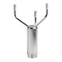
Ultrasonic Wind Sensor
Brand: Vaisala
|
Category: Security Sensors
|
Size: 6 MB
Table of Contents
-
Safety15
-
Recycling16
-
Trademarks18
-
Warranty18
-
Heating26
-
Accessories30
-
Manual31
-
Accessories32
-
Bird Cage33
-
WM Verifier34
-
Cables35
-
Profiles48
-
Protocols49
-
Unpacking64
-
Mounting65
-
Alignment76
-
Wiring79
-
Cables79
-
Heating84
-
Powering86
-
Configuration112
-
Status Flags125
-
Operating WMT700128
-
Data Messages129
-
Missing Readings135
-
Error Indication136
-
POLL - Poll Data139
-
Frequency143
-
Voltage144
-
Missing Readings157
-
Missing Readings160
-
Missing Readings164
-
Missing Readings166
-
Profile (V 1.3)167
-
SDI-12 Commands169
-
Address Query170
-
Ad0! - Send Data174
-
Command178
-
Missing Readings178
-
Cleaning182
-
Product Returns190
-
Technical Data191
-
Table 60 Outputs192
-
Table 61 General193
-
Dimensions195
-
Missing Readings214
Advertisement
Vaisala WMT702 User Manual (136 pages)
Ultrasonic Wind Sensor
Brand: Vaisala
|
Category: Accessories
|
Size: 2 MB
Table of Contents
-
-
Safety13
-
Recycling15
-
Trademarks16
-
Warranty16
-
-
Accessories22
-
Bird Cage23
-
WM Verifier24
-
Cables25
-
Overview31
-
-
-
Missing Readings101
-
Error Indication102
-
POLL - Poll Data105
-
-
Product Returns116
-
Technical Data117
-
Table 30 Outputs118
-
Table 31 General119
-
Dimensions121

Vaisala WMT702 Technical Reference (80 pages)
Ultrasonic Wind Sensor
Brand: Vaisala
|
Category: Security Sensors
|
Size: 1 MB
Table of Contents
Advertisement