
Related Manuals for Hyena DP-A250+


Summary of Contents for Hyena DP-A250+
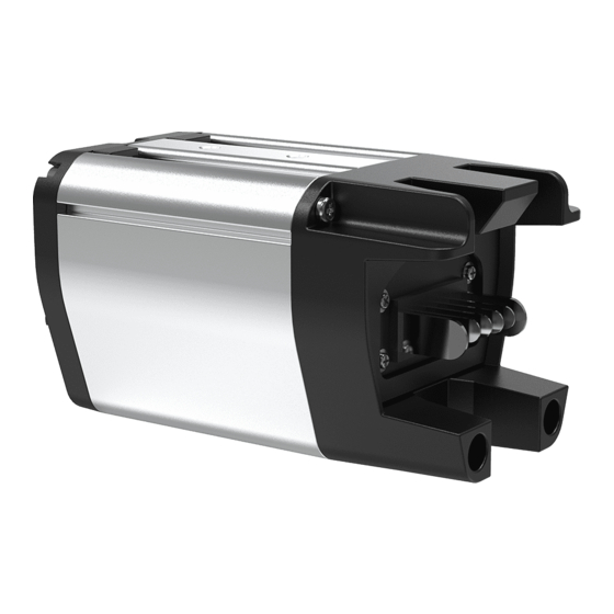
- Page 1 Product Manual DP-A250+ Original Instruction Version 221025 Copyright © 2022 HYENA INC. All Right Reserved.
-
Page 2: Table Of Contents
Table of Contents Introduction Product Features Product Description .................. 1 Parts Description ..................1 Product Dimension ................... 2 Pin Definition ..................... 3 Technical Data Characteristic .................... 5 Certification ....................5 Protection....................5 Software Standard Function ..............6 Mounting Tool List ....................7 Accessory List ................... -
Page 3: Introduction
Introduction This manual is intended primarily for the trained technician to install, disassemble, or maintain the Hyena e-bike system only. Please read all the safety warnings and instructions carefully. Failure to follow the warnings and instructions may result in death or severe injuries. Save this manual for future reference. -
Page 4: Product Dimension
Cable Length: 750±10 mm Rear Light Connector HMI Connector Outer Diameter: Ø 9.5 mm Outer Diameter: Ø 9.5 mm Cable OD: Ø 4 mm Cable OD: Ø 4 mm Cable Length: 750±10 mm Cable Length: 200±10 mm HYENA E-BIKE SYSTEMS... -
Page 5: Pin Definition
Cadence signal Cadence Cnk1 Input Cadence signal Torque Input Torque signal. Analog signal. Empty Empty Output 5V sensor power Output 5V sensor ground Rear Light Name Direction Description Remark Output Rear light power Bidirectional Rear light ground HYENA E-BIKE SYSTEMS... - Page 6 36V power output CANH Bidirectional CAN High CANL Bidirectional CAN Low Wakeup Bidirectional Active low, used to wakeup battery from sleep mode. Bike Present Output Active low, power appears only when low is detected. Ground Input Ground output HYENA E-BIKE SYSTEMS...
-
Page 7: Technical Data Characteristic
Hi-Pot No damage under 500V 60 seconds Brake sensor Front light 6V up to 3W Rear light 6V up to 3W Protocol Support Hyena CAN Certification EN 15194:2017 Including ISO 13849 UN38.3 IEC 62133 2006/66/EC Protection Each pin connecting to ground pin Short circuit protection introduces no permanent damage. -
Page 8: Software Standard Function
Motor phase Battery protocol Hyena proprietary protocol Parameter table Parameter 2.0 Error code table Hyena proprietary error code table Walk assistance Up to 4 km/hr Support level Standard 4 modes, Maximum 5 modes Level 1: 10±1 A Level 2: 12±1 A Current limit Level 3: 15±1 A... -
Page 9: Mounting
DP-A250+ Controller Installation Motor, Sensor and Rear Light STEP STEP Insert the controller through the frame tube. Pull out the connecting cables as the direction. STEP STEP Install the controller fixation cover and fasten screws. Completed. HYENA E-BIKE SYSTEMS... - Page 10 Replace and fasten the screw. Completed. Replace and fasten the screw. Remove the BP-A350 Battery STEP STEP Remove the screw by hexagon key or coin. STEP Slide out the battery through the frame tube. Insert and turn the key. HYENA E-BIKE SYSTEMS...
-
Page 11: Safety Instructions
• Do NOT place any heavy item on the product or any e- following: system component. • This product may only be used with the specific Hyena • Do NOT place the product or any e-system component e-bike battery (BP-A350). - Page 12 Hyena Inc. Tel: +886 4 23598810 Fax: +886 4 23598610 www.hyena-ebike.com Address: No.25, Jingke N. Rd., Nantun Dist., Taichung City 408, Taiwan (R.O.C.) HYENA E-BIKE SYSTEMS...
Need help?
Do you have a question about the DP-A250+ and is the answer not in the manual?
Questions and answers