Table of Contents
Advertisement
Quick Links
CAUTION, MICROWAVE RADIATION .............................................................................................................. 1
WARNING ........................................................................................................................................................... 1
PRODUCT SPECIFICATIONS .......................................................................................................................... 2
GENERAL INFORMATION ................................................................................................................................. 2
APPEARANCE VIEW ........................................................................................................................................ 3
OPERATION SEQUENCE ................................................................................................................................. 4
FUNCTION OF IMPORTANT COMPONENTS ................................................................................................. 8
SERVICING ..................................................................................................................................................... 11
TEST PROCEDURE ......................................................................................................................................... 14
TOUCH CONTROL PANEL .............................................................................................................................. 22
COMPONENT REPLACEMENT AND ADJUSTMENT PROCEDURE ............................................................ 28
MICROWAVE MEASUREMENT ..................................................................................................................... 34
WIRING DIAGRAM .......................................................................................................................................... 35
PICTORIAL DIAGRAM .................................................................................................................................... 37
CONTROL PANEL CIRCUIT ............................................................................................................................ 38
PRINTED WIRING BOARD .............................................................................................................................. 39
PARTS LIST .................................................................................................................................................... 40
SERVICE MANUAL
MODEL
In interests of user-safety the oven should be restored to its original
condition and only parts identical to those specified should be
used.
TABLE OF CONTENTS
SHARP CORPORATION
CONVECTION
MICROWAVE OVEN
R-995J
R-995J
S9409R995JPJ/
Page
Advertisement
Table of Contents

Related Manuals for Sharp R-995J


Summary of Contents for Sharp R-995J
-
Page 1: Table Of Contents
R-995J SERVICE MANUAL S9409R995JPJ/ CONVECTION MICROWAVE OVEN R-995J MODEL In interests of user-safety the oven should be restored to its original condition and only parts identical to those specified should be used. TABLE OF CONTENTS Page CAUTION, MICROWAVE RADIATION ......................1 WARNING ................................ - Page 2 R-995J...
-
Page 3: Caution Microwave Radiation
MICROWAVE OVEN R-995J APPEARANCE VIEW GENERAL IMPORTANT INFORMATION This Manual has been prepared to provide Sharp Corp. Service engineers with Operation and Service Information. OPERATING SEQUENCE It is recommended that service engineers carefully study the entire text of this manual, so they will be qualified to render satisfactory customer service. -
Page 4: Product Specifications
R-995J PRODUCT SPECIFICATIONS ITEM DESCRIPTION Power Requirements 230 - 240 Volts 50 Hertz Single phase, 3 wire earthed Power Consumption 1600 W (Microwave) 1600 W (Convection) Power Output 900 watts (IEC Test Procedure) Operating frequency of 2450MHz Convection heater 1500 W... -
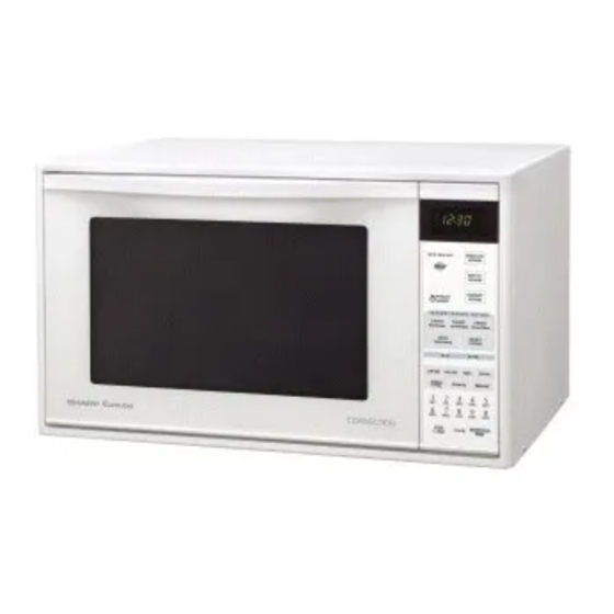
Page 5: Appearance View
R-995J APPEARANCE VIEW 1. Oven lamp 2. Door hinges 3. Door safety latches 4. See through door 5. Door seals and sealing surfaces 6. Touch control panel 7. Digital readout 8. Waveguide cover 9. Turntable motor shaft 10. Convection air openings 11. -
Page 6: Operation Sequence
The monitor switch is mechanically controlled by Figure O-1 on page 35 oven door, and monitors the operation of the right latch 1. The display shows "SHARP", "MICRO-", "WAVE" and switch and left latch switch. "OVEN". 6-1. When the oven door is opened during or after the 2. - Page 7 R-995J 2. The coil of relay (RY4) is energized by the CPU unit. and convection motor. The damper is moved to the closed position, opening 3. The shut-off relay (RY4) is energized. the damper switch contacts. The opening of the damper The damper door is closed from the open position.
- Page 8 R-995J sensor "senses" the vapour and its resistance increases oven will revert to an OFF condition. gradually. When the resistance reaches the value set WEIGHT SENSOR COOKING CONDITION according to the menu, supplementary cooking is started. In case where the weight sensor is used, the foods are...
- Page 9 R-995J Operation Please refer to the timing diagrams below. Following operation will start 4 minutes after the oven is started. 1. The thermistor operates within a 32-seconds time base and it is energized for three (3) seconds and off for 29 seconds.
-
Page 10: Function Of Important Components
R-995J FUNCTION OF IMPORTANT COMPONENTS RIGHT LATCH SWITCH AND LEFT LATCH SWITCH 1. When the oven door is closed, the contacts COM-NO ASYMMETRIC must be closed. RECTIFIER HIGH VOLTAGE 2. When the oven door is opened, the contacts COM-NO RECTIFIER must be opened. - Page 11 R-995J CONVECTION HEATER selected temperature, the convection heater is de-ener- gized. When the temperature inside the oven cavity drops The convection heater is located at the rear of the oven below the selected temperature, the convection heater is cavity. It is intended to heat air driven by the convection energized again.
- Page 12 R-995J 3-4. At the end of the convection cooking, shut-off relay (RY4) is energized, and the damper is returned to the open position. NOTE: If the damper door is not in the proper position, closed during convection or open during microwave, the control unit will stop oven operation after 1 minute.
-
Page 13: Servicing
If the water remains cold carry out 3D checks and re- examine the connections to the component being tested. Sharp recommend that wherever possible fault-finding is carried out with the supply disconnected. It may, in some cases, be necessary to connect the supply after... - Page 14 R-995J CK = Check / RE = Replace TEST PROCEDURE G RE POSSIBLE CAUSE DEFECTIVE PARTS PROBLEM CONDITION Home fuse blows when power supply cord is plugged into wall outlet. Fuse M8A blows when the door is opened. Fuse M8A blows when power cord is plugged into wall outlet.
- Page 15 R-995J O CK CK CK CK K CK CK P CK CK...
-
Page 16: Test Procedure
R-995J TEST PROCEDURES PROCEDURE COMPONENT TEST LETTER MAGNETRON TEST NEVER TOUCH ANY PART IN THE CIRCUIT WITH YOUR HAND OR AN INSULATED TOOL WHILE THE OVEN IS IN OPERATION. CARRY OUT 3D CHECK. Isolate the magnetron from high voltage circuit by removing all leads connected to filament terminal. - Page 17 R-995J TEST PROCEDURES PROCEDURE COMPONENT TEST LETTER Initial temperature ..................... T1 = 11°C Temperature after (47 + 3) = 50 sec..............T2 = 21°C Temperature difference Cold-Warm (∆T = T2 - T1) ......... ∆T = 10°C Measured output power The equation is “P = 90 x ∆T”...
- Page 18 R-995J TEST PROCEDURES PROCEDURE COMPONENT TEST LETTER rectifier, high voltage wire or filament winding of the power transformer is shorted. CARRY OUT 4R CHECKS. NOTE: FOR MEASUREMENT OF THE RESISTANCE OF THE RECTIFIER, THE BATTERIES OF THE MEASURING INSTRUMENT MUST HAVE A VOLTAGE AT LEAST 6 VOLTS, BECAUSE OTHERWISE AN INFINITE RESISTANCE MIGHT BE SHOWN IN BOTH DIRECTIONS.
- Page 19 R-995J TEST PROCEDURES PROCEDURE COMPONENT TEST LETTER Table: Temperature Fuse and Thermal cut-out Test Temperature of “ON” condition Temperature of “OFF” condition Indication ofohmmeter Parts Name (closed circuit) (˚C) (open circuit) (˚C) (When room temperature is approx. 20˚C) Temp. fuse 150˚C (MG) This is not resetable type.
- Page 20 R-995J TEST PROCEDURES PROCEDURE COMPONENT TEST LETTER MONITOR RESISTOR TEST CARRY OUT 3D CHECKS. Disconnect the leads from the monitor resist. Using an ohmmeter and set on a low range. Check between the terminals of the monitor resistor. The resistance of monitor resistor is approx. 0.8 ohms.
- Page 21 R-995J TEST PROCEDURES PROCEDURE COMPONENT TEST LETTER KEY UNIT TEST If the display fails to clear when the STOP/CLEAR pad is depressed, first verify the flat ribbon is making good contact, verify that the door sensing switch (stop switch) operates properly; that is the contacts are closed when the door is closed and open when the door is open.
- Page 22 R-995J TEST PROCEDURES PROCEDURE COMPONENT TEST LETTER NOTE: *At the time of making these repairs, make a visual inspection of the varistor. check for burned damage and examine the transformer with an ohmmeter for the presence of layer short-circuit (check primary coil resistance).
- Page 23 R-995J TEST PROCEDURES PROCEDURE COMPONENT TEST LETTER 6-1. Fill approximately 200 milliliters (7.2 oz) of tap water in a 1000 milliliter measuring cup. 6-2. Place the container on the center of tray in the oven cavity. 6-3. Close the door.
-
Page 24: Touch Control Panel
R-995J TEST PROCEDURES PROCEDURE COMPONENT TEST LETTER 13. Press the POWER LEVEL pad, and make sure that the display shows "01900 - 02100". 14. Disconnect the oven from power supply, and repeat above procedure items 1 to 7. 15. Press the "7" of number pads, and make sure that the display shows "01800 - 03200". - Page 25 R-995J DESCRIPTION OF LSI LSI(IZA723DR): The I/O signals of the LSI(IZA723DR) are detailed in the following table. Pin No. Signal Description Connected to GND. Anode (segment) of Fluorescent Display light-up voltage: -30V. Vp voltage of power source circuit input. AVSS Power source voltage: -5V.
- Page 26 R-995J Pin No. Signal Description Magnetron high-voltage circuit driving signal. To turn on and off the cook relay(RY2). In HIGH operation, the VARI MODE ON TIME OFF TIME signals holds "L" level during micro- HIGH (100% power) 32 sec. 0 sec.
- Page 27 R-995J Pin No. Signal Description Signal similar to P27. When any one of G-2 line key on key matrix is touched, a corresponding signal will be input into P26. Signal similar to P27. When any one of G-3 line key on key matrix is touched, a corresponding signal will be input into P25.
- Page 28 R-995J Pin No. Signal Description 49-53 P07-P03 Segment data signal. Signal similar to P23. 54-56 P02-P00 Digit selection signal. Signal similar to P55. 57-59 P37-P35 Digit selection signal. Signal similar to P55. 60-64 P34-P30 Used for initial balancing of the bridge circuit (absolute humidity sensor).
- Page 29 R-995J SERVICING 1. Precautions for Handling Electronic Components For those models, check and repair all the controls This unit uses CMOS LSI in the integral part of the (sensor-related ones included) of the touch control circuits. When handling these parts, the following panel while keeping it connected to the oven.
-
Page 30: Component Replacement And Adjustment Procedure
4. If the outer case (cabinet) is not fitted. Please refer to ‘OVEN PARTS, CABINET PARTS, DOOR PARTS’, when carrying out any of the following removal procedures: WARNING FOR WIRING 3) Sharp edge: To prevent an electric shock, take the following Bottom plate, Oven cavity, Weveguide flange, manners. - Page 31 R-995J leads of transformer to the magnetron and capacitor, NOTE; LIVE (ORANGE) WIRE MUST BE CONNECTED referring to the "Pictorial Diagram". TO THE CABINET-SIDE OF THE POWER 6. Re-install the outer case and check that the oven is TRANSFORMER. operating properly.
- Page 32 R-995J frame, adjust the upper edge and right edge of NOTE: 1. Before attaching a new key unit, remove the key unit to the correct position of control remaining adhesive on the control panel frame panel frame. surfaces completely with a soft cloth soaked in 3.
- Page 33 R-995J HEATER UNIT ASSEMBLY REMOVAL (HEATING ELEMENT/THERMISTOR) protection sheet (left) from the heater duct assembly. 1. CARRY OUT 3D CHECKS. 14.Remove two (2) screws holding the convection heater 2. Remove convection motor assembly refer to to the heater duct assembly.
- Page 34 R-995J LATCH HOOK (RIGHT) LATCH HOOK (LEFT) STOPPER SWITCH STOPPER LEVER STOP SWITCH SWITCH MONITOR LEVER L SWITCH Pole Pole LEFT LATCH SWITCH RIGHT LATCH SWITCH STOPPER Figure C-3. Switches RIGHT AND LEFT LATCH SWITCHES, STOP SWITCH AND MONITOR SWITCH ADJUSTMENT If the right latch switch, left latch switch, stop switch and 2.
- Page 35 R-995J 11.CARRY OUT 4R CHECKS. 3. The door is positioned with its face depressed toward NOTE: After any service to the door; the cavity face plate. An approved microwave survey meter should be 4. Re-install outer case and check for microwave leakage...
-
Page 36: Microwave Measurement
R-995J MICROWAVE MEASUREMENT Recommended instruments are: After adjustment of door latch switches, monitor switch NARDA 8100 and door are completed individually or collectively, the NARDA 8200 following leakage test must be performed with a survey HOLADAY HI 1500 instrument and it must be confirmed that the result meets... -
Page 37: Wiring Diagram
R-995J SCHEMATIC NOTE: CONDITION OF OVEN 1. DOOR CLOSED. NOTE: indicates components with potential above 250V. 2. CLOCK APPERARS ON DISPLAY THERMAL CUT-OUT 145˚C (MG) TEMP. FUSE 150˚C (MG) THERMAL CUT-OUT 150˚C (OVEN) Figure O-1. Oven Schematic-OFF Condition SCHEMATIC SCHEMATIC... - Page 38 R-995J SCHEMATIC NOTE: CONDITION OF OVEN 1. DOOR CLOSED. 2. CONVECTION PAD TOUCHED. 3.DESIRED TEMO. PAD TOUCHED. NOTE: indicates components with potential above 250V. 4. START PAD TOUCHED. THERMAL CUT-OUT 145˚C (MG) TEMP. FUSE 150˚C (MG) THERMAL CUT-OUT 150˚C (OVEN) Figure O-3.
-
Page 39: Pictorial Diagram
R-995J HV. RECTIFIER... -
Page 40: Control Panel Circuit
R-995J... -
Page 41: Printed Wiring Board
R-995J (C81) R86(J8) (C80) (R45) (C45) (CN - D) (R47) (R48) (R49) (C46) (C47) (J7) (J5) (J3) (J2) (J4) (J6) CONV HEATER COM Figure S-3. Printed Wiring Board... -
Page 42: Parts List
R-995J PARTS LIST ∆ Note: The parts marked " " may cause undue microwave exposure. The parts marked "*" are used in voltage more than 250V. REF. NO. PART NO. DESCRIPTION Q'TY CODE ELECTRICAL PARTS 1- 1 FH-DZA058WRK0 High voltage rectifier assembly... - Page 43 R-995J ∆ Note: The parts marked " " may cause undue microwave exposure. The parts marked "*" are used in voltage more than 250V. REF. NO. PART NO. DESCRIPTION Q'TY CODE VCEAB31VW106M Capacitor 10µF 35V RC-KZA087DRE0 Capacitor 0.1µF 50V VCEAB31VW106M Capacitor 10µF 35V...
- Page 44 R-995J ∆ Note: The parts marked " " may cause undue microwave exposure. The parts marked "*" are used in voltage more than 250V. REF. NO. PART NO. DESCRIPTION Q'TY CODE 4- 8 LFIX-A013WRW0 Bearing holder plate 4- 9 NFANMA019WRW0...
- Page 45 R-995J REF. NO. PART NO. DESCRIPTION Q'TY CODE 7- 3 XCTWW40P08000 Screw; 4mm x 7- 4 XCBWW30P06000 Screw; 3mm x 7- 5 LX-CZ0052WRE0 Special screw 7- 6 XBPSD40P06KS0 Screw; 4mm x 7- 7 XOTSD40P12RV0 Screw; 4mm x 12mm 7- 8 XJPSD40P10000 Screw;...
- Page 46 R-995J...
- Page 47 R-995J CONTROL PANEL PARTS 3-1F 3-1G 3-2-1 7-24 DOOR PARTS 4-41 MISCELLANEOUS Actual wire harness may be different than illustration. 6-10 6-12...
- Page 48 R-995J '04SHARP CORP. (9S0.CD_E)
Need help?
Do you have a question about the R-995J and is the answer not in the manual?
Questions and answers