Table of Contents
Advertisement
CHAPTER 1. BEFORE SERVICING
CHAPTER 2. WARNING TO SERVICE PERSONNEL
CHAPTER 3. PRODUCT SPECIFICATIONS
CHAPTER 4. APPEARANCE VIEW
CHAPTER 5. OPERATION SEQUENCE
CHAPTER 6. FUNCTION OF IMPORTANT COMPO-
NENTS
CHAPTER 7. TROUBLESHOOTING GUIDE
SHARP CORPORATION
SERVICE MANUAL
MODELS
In the interest of user-safety the oven should be restored to its
original condition and only parts identical to those specified
should be used.
CONTENTS
CHAPTER 8. TEST PROCEDURES
CHAPTER 9. TOUCH CONTROL PANEL ASSEMBLY
CHAPTER 10. COMPONENT REPLACEMENT AND
ADJUSTMENT PROCEDURE
CHAPTER 11. MICROWAVE MEASUREMENT
CHAPTER 12. CIRCUIT DIAGRAMS
Parts List
SX517R990KPJW
CONVECTION
MICROWAVE OVEN
R-990K(S)
R-990K(W)
This document has been published to be used
for after sales service only.
The contents are subject to change without notice.
R990K(W)
Advertisement
Table of Contents

Related Manuals for Sharp R-990KS


Summary of Contents for Sharp R-990KS
-
Page 1: Microwave Oven
CHAPTER 12. CIRCUIT DIAGRAMS CHAPTER 6. FUNCTION OF IMPORTANT COMPO- NENTS Parts List CHAPTER 7. TROUBLESHOOTING GUIDE This document has been published to be used SHARP CORPORATION for after sales service only. The contents are subject to change without notice. -
Page 2: Table Of Contents
CONTENTS CHAPTER 1. BEFORE SERVICING Procedure G: TEMPERATURE FUSE GENERAL IMPORTANT INFORMATION ..1-1 AND TERMAL CUT-OUT TEST ....8-3 CAUTION MICROWAVE RADIATION ..1-1 Procedure H: CONVECTION HEATER WARNING ..........1-1 TEST............8-3 Procedure I: THERMISTOR TEST ..... 8-3 CHAPTER 2. -
Page 3: Chapter 1. Before Servicing
[1] GENERAL IMPORTANT INFORMATION This Manual has been prepared to provide Sharp Corp. Service engineers with Operation and Service Information. It is recommended that service engineers carefully study the entire text of this manual, so they will be qualified to render satisfactory customer ser- vice. -
Page 4: Chapter 2. Warning To Service Personnel
When the two minutes has elapsed (timer at zero) carefully check that Sharp recommend that wherever possible fault-finding is carried out the water is now hot. If the water remains cold carry out 3D checks and with the supply disconnected. It may, in some cases, be necessary to reexamine the connections to the component being tested. -
Page 5: Chapter 3. Product Specifications
R990K(W) CHAPTER 3. R990K(W) PRODUCT SPECIFICATIONS Service Manual DESCRIPTION 230 - 240 Volts Power Requirements 50 Hertz Single phase, 3 wire earthed 1600 W (Microwave) Power Consumption 1600 W (Convection) 900 watts (IE60705C) Power Output Operating frequency 2450 MHz Width 627 mm Case Dimensions Height 378 mm Depth 487 mm... -
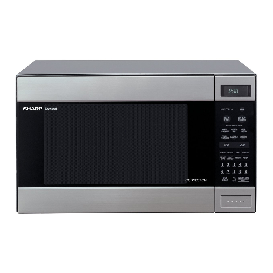
Page 6: Chapter 4. Appearance View
R990K(W) CHAPTER 4. R990K(W) APPEARANCE VIEW Service Manual [1] OVEN 1. Ventilation opening 2. Oven lamp 3. Door hinges 4. Door safety latches 5. See through door 6. Door seal and sealing surfaces 7. Door open button 8. Touch control panel 9. -
Page 7: Chapter 5. Operation Sequence
Figure O-1 on page 12-1 1. The display flashes “SHARP”, “MICRO-”, “WAVE”,'OVEN”. 2. MEDIUM HIGH, MEDIUM, MEDIUM LOW, LOW COOKING To set any programmes or set the clock, you must first touch the STOP/CLEAR pad. -
Page 8: Automatic Mix Cooking Condition
R990K(W) 2) The oven will continue to function for 30 minutes, turning the convection heater on and off, as needed to maintain the 8 S E C . 40 S E C . selected preheat temperature. The oven will shut-down com- pletely after 30 minutes. -
Page 9: Ah Sensor Cooking Sequence
R990K(W) [9] FIRE SENSING FEATURE (MICROWAVE MODE) AH S E NS OR This model incorporates a sensing feature which will stop the oven's operation if there is a fire in the oven cavity during microwave cooking. This accomplished by the LSI repeatedly measures the voltage across the temperature measurement circuit (thermistor) during it's 32-sec- onds time base comparing the obtained voltage measurements. -
Page 10: Chapter 6. Function Of Important Compo
R990K(W) CHAPTER 6. R990K(W) FUNCTION OF IMPORTANT COMPONENTS Service Manual [1] DOOR OPEN MECHANISM [4] THERMAL CUT-OUT 150C (CONV.) The door is opened by pushing the open button on the control panel, The oven thermal cut-out located on the left side of the thermal protec- refer to the Figure D-1.When the open button is pushed, the open tion plate is designed to prevent damage to the convection heater unit lever pushes up the switch lever, and then the switch lever pushes up... -
Page 11: Convection Cooking System
R990K(W) [13] CONVECTION COOKING SYSTEM 1) Damper motor is energized by touching the convection, temper- ature and START pads. This oven is designed with a hot air heating system where food is not 2) When damper is in the closed position (dampers witch is OFF), directly heated by the convection heater, but is heated by forced circu- its signal is sensed by the control unit, and shut-off relay (RY4) lation of the hot air produced by the convection heater. -
Page 12: Chapter 7. Troubleshooting Guide
R990K(W) CHAPTER 7. R990K(W) TROUBLESHOOTING GUIDE Service Manual [1] FOREWORD When troubleshooting the microwave oven, it is helpful to follow the IMPORTANT: Sequence of Operation in performing the checks. Many of the possible If the oven becomes inoperative because of a blown fuse F10A in the causes of trouble will require that a specific test be performed. -
Page 13: Chapter 8. Test Procedures
R990K(W) CHAPTER 8. R990K(W) TEST PROCEDURES Service Manual [1] Procedure A: MAGNETRON (MG) TEST NEVER TOUCH ANY PART IN THE CIRCUIT WITH YOUR HAND OR AN INSULATED TOOL WHILE THE OVEN IS IN OPERATION. CARRY OUT 3D CHECKS. Isolate the magnetron from the high voltage circuit by removing all leads connected to the filament terminal. To test for an open circuit filament use an ohmmeter to make a continuity test between the magnetron filament terminals, the meter should show a reading of less than 1 ohm. -
Page 14: Procedure B: Power Transformer Test
R990K(W) 1000g 1000g 1000g T1 C T2 C Heat up for 50 sec. [2] Procedure B: POWER TRANSFORMER TEST WARNING: High voltages and large currents are present at the secondary winding and filament winding of the power transformer. It is very dangerous to work near this part when the oven is on. -
Page 15: Procedure E: Switch Test
R990K(W) [5] Procedure E: SWITCH TEST CARRY OUT 3D CHECKS. Isolate the switch to be tested and using an ohmmeter check between the terminals as described in the following table. Table: Terminal Connection of Switch Plunger Operation Common terminal to Normally open terminal Common terminal to Normally close terminal Released Open circuit... -
Page 16: Procedure J: Motor Winding Test
R990K(W) Room Temp....20°C - 30°C Resistance.....Approx. 350kΩ - 155kΩ If the meter does not indicate above resistance, replace the thermistor. CARRY OUT 4R CHECKS. [10] Procedure J: MOTOR WINDING TEST CARRY OUT 3D CHECKS. Disconnect the leads from the motor. Using an ohmmeter, check the resistance between the two terminals as described in the table below. Table: Resistance of Motor Motors Resistance... -
Page 17: Procedure N: Key Unit (Membrane Switch) Test
R990K(W) c) Only one indicator does not light up. d) The corresponding segments of all digits do not light up; or they continue to light up. e) Wrong figure appears. f) A certain group of indicators do not light up. g) The figure of all digits flicker. -
Page 18: Procedure Q: Ah Sensor Test
R990K(W) Power transformer or secondary circuit defective. The rated voltage is applied to primary side of power transformer. Check and repair. Only pattern at “a” is broken. *Insert jumper wire J1 and solder. Pattern at “a” and “b” are broken. *Insert the coil RCILF2003YAZZ between “c”... - Page 19 R990K(W) f) The display will start to count down the remaining cooking time, and the oven will turn off automatically after the water is boiling (babbling). If new sensor dose not operate properly, the problem is with the control unit. 2.
-
Page 20: Chapter 9. Touch Control Panel Assem
R990K(W) CHAPTER 9. R990K(W) TOUCH CONTROL PANEL ASSEMBLY Service Manual [1] OUTLINE OF TOUCH CONTROL PANEL 4) ACL Circuit A circuit to generate a signals which resetting the LSI to the initial The touch control section consists of the following units as shown in state when power is applied. - Page 21 R990K(W) Pin No. Signal Description Digit selection signal. The relationship between digit signal and digit are as fol- ß(50Hz) lows; Digit signal Digit G ND P02......2nd. P03......1st. P 03 P01......3rd. P 02 P00......4th. P37......5th. P 01 P36......6th. P 00 P35......
- Page 22 R990K(W) Pin No. Signal Description Signal to synchronize LSI with commercial power source freqency. This is the basic timing for all real time processing of LSI. H : GND INT1 L (-5V) 20 msec. Connected to GND. Auto clear terminal. Signal is input to reset the LSI to the initial state when power is applied.
-
Page 23: Absolute Humidity Sensor Circuit
R990K(W) Pin No. Signal Description Segment data signal. Signal similar to P23. Key strobe signal. Signal applied to touch-key section. A pulse signal is input to P24-P27 terminal while one of G-6 line keys on key matrix is touched. Segment data signal. Signal similar to P23. -
Page 24: Servicing For Touch Control Panel
R990K(W) [4] SERVICING FOR TOUCH CONTROL PANEL 1. Precautions for Handling Electronic Components 2. Servicing the touch control panel with power supply from an exter- nal power source: This unit uses CMOS LSI in the integral part of the circuits. When han- Disconnect the touch control panel completely from the oven dling these parts, the following precautions should be strictly followed. -
Page 25: Precautions For Using Lead-Free Solder
R990K(W) [5] PRECAUTIONS FOR USING LEAD-FREE SOLDER 1. Employing lead-free solder The “Main PWB” of this model employs lead-free solder. This is indicated by the “LF” symbol printed on the PWB and in the service manual. The suffix letter indicates the alloy type of the solder. Example: Indicates lead-free solder of tin, silver and copper 2. -
Page 26: Chapter 10. Component Replacement And Adjustment Procedure Before Operating
Please refer to ”OVEN PARTS, CABINET PARTS, DOOR PARTS”, when carrying out any of the following removal procedures: WARNING FOR WIRING To prevent an electric shock, take the following precautions. 3) Sharp edge: 1. Before wiring, Bottom plate, Oven cavity, Weveguide flange, Chassis support and other metallic plate. -
Page 27: Power Transformer Removal
R990K(W) [3] POWER TRANSFORMER REMOVAL 1. REMOVAL 2. Insert the two edges of the transformer into two metal tabs of the base cabinet. 1. CARRY OUT 3D CHECKS. 3. Make sure the transformer is mounted correctly to the corners 2. Disconnect the wire leads from power transformer. underneath those tabs. -
Page 28: Control Panel Assembly And Control Unit Removal
R990K(W) 2. HEATING ELEMENT AND THERMISTOR 3. Heating element is free. 4. Remove two (2) screws holding thermistor to heater duct. 1. Remove two (2) screws holding heating element to heater duct. 5. Thermistor is free. 2. Loosen two (2) screws holding holders to heater duct and take heating element out of heating element holders. -
Page 29: Cord Holder Removal
R990K(W) CAUTION: 2) Apply the screw lock tight into the hole (for shaft) of the fan blade. • Do not use this removed fan blade again. Because the hole (for shaft) of it may become bigger than a standard 3) Install the fan blade assembly to the shaft of fan motor by push- one. -
Page 30: Microwave Measurement
R990K(W) [16] STOP SWITCH, UPPER LATCH SWITCH, LOWER LATCH SWITCH AND MONITOR SWITCH REMOVAL 1. REMOVAL 2. REINSTALL 1. CARRY OUT 3D CHECKS. 1. Re-install latch lever and each switch in its place, refer to Figure C- 2. Remove control panel assembly, refer to “Control Panel Removal”. 2. -
Page 31: Door Glass
R990K(W) 1. Door latch heads smoothly catch the latch hook through the latch holes, and the latch head goes through the center of the latch hole. 2. Deviation of the door alignment from horizontal line of cavity face UP P E R OV E N HING E plate is to be less than 1.0mm. - Page 32 R990K(W) CHAPTER 11. R990K(W) MICROWAVE MEASUREMENT Service Manual After adjustment of door latch switches, monitor switch and door are completed individually or collectively, the following leakage test must be per- formed with a survey instrument and it must be confirmed that the result meets the requirements of the performance standard for microwave oven. REQUIREMENT The safety switch must prevent microwave radiation emission in excess of 5mW/cm at any point 5cm or more from external surface of the oven.
-
Page 33: Circuit Diagrams
R990K(W) CHAPTER 12. R990K(W) CIRCUIT DIAGRAMS Service Manual [1] Oven Schematic SCHEMATIC NOTE: CONDITION OF OVEN 1. DOOR CLOSED. 2. CLOCK APPEARS ON DISPLAY. THERMAL CUT-OUT NOTE: " " indicates components with potentials above 250V 145¡C (MAGNETRON) THERMAL CUT-OUT TEMPERATURE 95¡C (FAN) FUSE 150¡C NOISE FILTER... - Page 34 R990K(W) SCHEMATIC NOTE: CONDITION OF OVEN 1. DOOR CLOSED. 2. MIX COOKING PAD TOUCHED. 3. COOKING TIME PROGRAMMED. 4. START PAD TOUCHED. 5. RY2 AND RY3 WILL ALTERNATELY CLOSED DURING COOK CYCLE. THERMAL CUT-OUT 145¡C (MAGNETRON) NOTE: " " indicates components with potentials above 250V TEMPERATURE THERMAL CUT-OUT 95¡C (FAN)
- Page 35 R990K(W) [2] Pictorial Diagram (Figure S-1) HV. RECTIFIER Figure S-1. Pictorial Diagram 12 – 3...
- Page 36 R990K(W) [3] Control Unit Circuit (Figure S-2) 3.3k 3.3k 3.3k 3.3k 3.3k 3.3k 3.3k 100k 100k 100k 3.3k R100 3.3k 3.3k 3.3k 3.3k IZA840DR 4.7k 2.2kF (J7) 4.7k (J5) HZ4A2 100F (J3) 10μ/35v (J6) 0.1μ/50v (J4) 0.01μ/50v HZ5C2 (J2) /25v 22μ...
- Page 37 R990K(W) [4] Printed Wiring Board (Figure S-3) R 91 R 80 R 92 C 10 R 81 R 93 R 73 (C 81) R 72 R 86(J 8) R 71 R 70 (C 80) (R 45) (C 45) (C N - D) R 79 R 78 R 77...
- Page 38 R990K(W) MEMO 12 – 6...
-
Page 39: Parts List
BOTTOM PAD ASSEMBLY FPADBA363WRK0 TRAY PACKING FOAM PACKING CASE SPADPA198WRE0 SPAKCE322WREZ [R-990K(S)] SPAKCE323WREZ [R-990K(W)] Not replaceable items. This document has been published to be used SHARP CORPORATION for after sales service only. The contents are subject to change without notice. - Page 40 R990K(W) [1] OVEN PARTS...
- Page 41 R990K(W) PRICE PART PARTS CODE DESCRIPTION RANK MARK RANK [1] OVEN PARTS ELECTRICAL PARTS FH-DZA053WRK0 High voltage rectifier assembly FH-HZA041WRE0 Thermistor assembly QACC-A141WRZZ Power supply cord QACC-A155WRZZ Power supply cord (Interchnageable) (for production use) QFS-CA026WRZZ Fuse F10A QFS-TA013WRE0 Temperature fuse 150C (Magnetron) RTHM-A080WRE0 Thermal cut-out 145C (Magnetron) (Interchangeable) RTHM-A112WRE0...
- Page 42 R990K(W) PRICE PART PARTS CODE DESCRIPTION RANK MARK RANK [1] OVEN PARTS 4-14 PCUSUA167WRP0 Cushion 4-15 PCUSUA424WRP0 Cushion 4-16 FDUC-A322WRW0 Steam duct assembly 4-17 MCAMPA030WRF0 Damper cam 4-18 NSFTTA114WRE0 Damper shaft 4-19 FFTA-A034WRK0 Damper door assly 4-20 PDUC-A269WRW0 Damper duct 4-21 PCUSGA410WRP0 Cushion...
- Page 43 R990K(W) [2] DOOR AND CONTROL PANEL PARTS 3-1E 6-10 3-1F 7-18 3-2-4 7-18 3-2-6 3-2-1 3-2-5 3-2-3 3-2-2 5-15 3-2-7 5-12 5-13 5-11 5-12 5-11 5-11 5-10 5-11 5-14 Actual wire harness may be different than illustration.
- Page 44 R990K(W) PRICE PART PARTS CODE DESCRIPTION RANK MARK RANK [2] DOOR AND CONTROL PANEL PARTS CONTROL PANEL PARTS DPWBFB724WRU0 Control unit (New Zealand only) 3-1E RV-KXA077DRE0 Fluorescent display tube 3-1F PCUSGA381WRP0 Cushion DPNLCB960WRKZ Control panel frame with key unit [R-990K(W)] DPNLCB958WRKZ Control panel frame with key unit [R-990K(S)] 3-2-1...
- Page 45 R990K(W) PRICE PART PARTS CODE DESCRIPTION RANK MARK RANK [3] OTHER VCEAB31VW106M Capacitor 10uF 35V VCEAB31HW104M Capacitor 0.1uF 50V RC-KZA087DRE0 Capacitor 0.1uF 50V VCKYD11CY103N Capacitor 0.01uF 16V VCKYD11CY103N Capacitor 0.01uF 16V VCKYD11CY103N Capacitor 0.01uF 16V RMPTEA009DRE0 Capacitor array 330pF x 4 RCRS-A035DRE0 Ceramic resonator (CST4.19MGW) D1-4...
- Page 46 R990K(W) INDEX PRICE PART PRICE PART PARTS CODE PARTS CODE RANK MARK RANK RANK MARK RANK 1-4-22 NCPL-A021WRF0 [ C ] 1-4-32 CDORFB034WRKZ NFANJA020WRE0 NFANMA019WRW0 1-4-9 CDORFB035WRKZ NPLYBA025WRF0 1-4-10 [ D ] 2-3-5 NSFTTA042WRE0 2-5-1 DDORFA820WRY0 1-4-18 NSFTTA114WRE0 DPNLCB958WRKZ 2-3-2 1-4-3 NTNT-A019WRH0 DPNLCB960WRKZ...
- Page 47 R990K(W) PRICE PART PRICE PART PARTS CODE PARTS CODE RANK MARK RANK RANK MARK RANK 1-1-19 RTHM-A099WRE0 [ X ] 1-1-20 RTHM-A111WRE0 1-7-9 XBPS730P14K00 1-1-5 RTHM-A112WRE0 XBPS740P06KS0 1-7-14 RTHM-A117WRE0 1-1-20 XBPS740P25000 1-7-10 RTHM-A120WRE0 1-1-5 1-7-11 XBTWW40P06000 1-1-19 RTHM-A121WRE0 1-7-21 XCBWW30P06000 1-1-21 RTRN-A545WRE0 1-7-17...
- Page 48 COPYRIGHT © 2005 BY SHARP CORPORATION ALL RIGHTS RESERVED. No part of this publication may be reproduced, stor- ed in retrieval systems, or transmitted in anyform or by any means, electronic, mechanical, photocopy- ing, recording, or other wise, without prior written ©...
Need help?
Do you have a question about the R-990KS and is the answer not in the manual?
Questions and answers