Table of Contents
Advertisement
Quick Links
WPC-15000
WMC-2500
Owner's Manual
Please read and save these instructions. Read carefully before attempting to assemble, install, oper-
ate or maintain the product described.
Protect yourself and others by observing all safety information. Failure to comply with instructions
could result in personal injury and property damage! Retain instructions for future reference.
Modular Multi Air Conditioner
Descripti on
Koldwave Modular Multi Air conditi oner feature multi -functi on spot cooler providing various ac-
cessories available to fi t customer needs. This Unit is used to spot cooling for large areas where
cooling of the enti re area is not practi cal or possible. A dedicated spot cooling thermostat controls
the unit in this applicati on. This Unit can also be used in smaller areas for room cooling.
A control panel provides ease of use and contains a self-diagnosti c functi on and display, showing
operati ng modes, room and set temperatures, and faults, If an abnormal operati on occurs, a visual
display of the fault is shown.
Suitable applicati ons include :
a factory or work place, computer rooms, emergency cooling, etc..
Unpacking
Aft er unpacking the unit, carefully inspect unit for any damage that may have occurred during
transit. Check for any loose, missing or damaged parts.
1
Owner's Manual
Owner's Manual
6CC10BEA2AA00
6CC10BEA2AA00
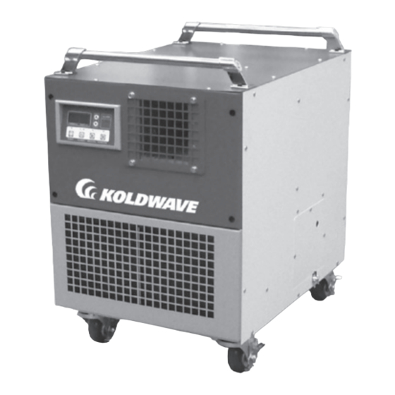
Figure 1
Advertisement
Table of Contents

Subscribe to Our Youtube Channel
Related Manuals for Koldwave K6CC10BEA2AA00


Summary of Contents for Koldwave K6CC10BEA2AA00
- Page 1 Figure 1 Descripti on Koldwave Modular Multi Air conditi oner feature multi -functi on spot cooler providing various ac- cessories available to fi t customer needs. This Unit is used to spot cooling for large areas where cooling of the enti re area is not practi cal or possible. A dedicated spot cooling thermostat controls the unit in this applicati on.
-
Page 2: Table Of Contents
6CC10BEA2AA00 Owner’s Manual Table of Contents SPECIFICATION.....................4 GENERAL SAFETY INFORMATION..............4 APPLICATIONS....................6 Portable Server Rack Mounted, Hang Stack ASSEMBLY (STANDARD)................7 Component Parts Power Cord Holder ASSEMBLY (PORTABLE).................8 Component Parts Handle Cool air duct assembly Caster ASSEMBLY (SERVER RACK)................9 Component Parts Universal adjust Rack Assembly Rack Diffuser ASSEMBLY (MOUNTED, HANG)..............10... - Page 3 6CC10BEA2AA00 Owner’s Manual Shipping list Modular air conditioner 1 unit Owner’s Manual 1 pcs Power Cord Holder 1 pcs Drain hose (20ft length) 1 pcs * The 6CC10BEA2AA00 is used in conjunction with various accessories to adapt to your environmental needs. These accessories (Portable Kit, Server Rack Kit, Hanging Kit, Stack Kit) are sold separately to allow you to customize the 6CC10BEA2AA00 to your specific needs...
-
Page 4: Specification
6CC10BEA2AA00 Owner’s Manual Specifications Cooling Capaci- Power Consump- Rated Cur- EER Btu/ Model No. Power Supply Ph-V-Hz ty Btu/h tion Watts rent Amps 6CC10BEA2AA00 Single Phase, 115V, 60Hz 10,000 1000 10.0 Power Cord Power Cord Length Dimensions Model No. Nema Plug Gauge AWG W x D x H - in. - Page 5 6CC10BEA2AA00 Owner’s Manual 7. DO NOT cover or obstruct the unit’s inlet and outlet grilles. 8. DO NOT use the unit in areas where it will be exposed to rain or water. 9. NEVER unplug the while it is operating. DO NOT use the unit in wet environments, such as a laundry room, to avoid the risk of electrical shock.
-
Page 6: Applications
6CC10BEA2AA00 Owner’s Manual Applications With various accessories, Modular multi air conditioner provides best application to suit custom- er’s individual needs. PORTABLE - This unit has ability to move easily from room to room using portable kit. It is available spot cooling for large areas where cooling of the entire area in not practical. -
Page 7: Assembly (Standard)
6CC10BEA2AA00 Owner’s Manual ASSEMBLY (Standard) COMPONENT PARTS Display /Control Panel Cool Air Outlet Evaporator / Filter Figure 2 - front and Right Side View Exhaust Air Outlet Electrical Access Drain Pump Hose Panel Connector Power cord Figure 3 - rear and Power cord Holder Left Side View Condenser / Filter... -
Page 8: Assembly (Portable)
6CC10BEA2AA00 Owner’s Manual ASSEMBLY (Portable) COMPONENT PARTS Handle Cool air duct Caster Figure 5 - portable kit attachment Figure 6 - handle Figure 7 - cool air duct attachment assy attachment HANDLE COOL AIR DUCT ASSEMBLY 1. Take out the handle 2 pcs from the accesso- 1. -
Page 9: Assembly (Server Rack)
6CC10BEA2AA00 Owner’s Manual ASSEMBLY (Server Rack) COMPONENT PARTS Rack diffuser Universal adjust * See Figure 19 on page 12. Rack assembly Figure 9 - server rack kit attachment Figure 10 - installation in 19” server rack RACK ASSEMBLY 1. Assemble the rack assembly parts 1set (6ea) to fit in server rack. -
Page 10: Assembly (Mounted, Hang)
6CC10BEA2AA00 Owner’s Manual ASSEMBLY (Mounted, Hang) COMPONENT PARTS Condenser intake air outlet Eva intake air outlet Figure 14 - Rear and Figure 13 - Front and Left Side View Right Side View CONDENSER INTAKE AIR DUCT FLANGE 1. Remove condenser intake air duct flange (includ- ed filter) 1 pcs from carton. - Page 11 6CC10BEA2AA00 Owner’s Manual HANGING ASSEMBLY 1. Install 1/2” threaded rod and vibration insulator to ceiling. 2. Remove Hanging assembly 1 set (2ea) from carton. 3. Place the hanging assy horizontally on the base of air conditioner. 4. Use screw (enclosed inside of box with hanging kit) to install as shown in Figure 17.
-
Page 12: Assembly (Stack)
6CC10BEA2AA00 Owner’s Manual ASSEMBLY (Stack) COMPONENT PARTS Figure 19 - universal adjust attachment UNIVERSAL ADJUST 1. Take out the universal adjust 4 pcs from the acces- sory box. 2. Place the universal adjust on the base panel of unit. 3. Install on the unit as shown in Figure 19. DO NOT tilt the unit on it’s side. -
Page 13: Installation Guide
6CC10BEA2AA00 Owner’s Manual Installation Guide WARNING REGARDING PROPER LOCATION FOR INSTALLATION Do not use the unit in explosive environments or in areas where flammable gas leakage may occur. Do not use the unit in a corrosive atmosphere. Do not use the unit above 18˚C(64.4˚F)~45˚C(113˚F) Do not install the unit on uneven or sloping surface. -
Page 14: Operation
6CC10BEA2AA00 Owner’s Manual Operation CONTROL PANEL Figure 8 1. POWER BUTTON: Activates unit when POWER BUTTON is pressed. (Fan starts on low speed). If power button is pressed during operation, unit stops. 2. BLOW BUTTON: Changes fan speed from 1)low, 2)high, 3) Auto when pressed. Low is left lamp, high is right, Auto is two lamp on. - Page 15 6CC10BEA2AA00 Owner’s Manual 8. TARGET: Displays Target Temperature and Humidity set by pressing button +/- respectively. 9. ALARM: Alarm indicator lights(blinks) and indicates abnormal system operation. If Alarm occurs, compressor stops. System operation stops when ALARM light is activated(blinks) longer than 3 minutes.
-
Page 16: Maintenance
6CC10BEA2AA00 Owner’s Manual Maintenance FILTER CLEANING (Without flange) There are 2 filters in the unit. The evaporator filter is located at the front of the unit. The con- denser filter is located at the rear of the unit. 1. Open the front grill. 2. - Page 17 6CC10BEA2AA00 Owner’s Manual FILTER CLEANING (With flange) 1. Loosen up 2 bolts on flange. 2. Slide filter up and use vacuum cleaner to remove the dust from the filter. 3. If the filter is heavily covered with dust and dirt, warm water and mild soap or neutral deter- gent may be used to wash the filter.
- Page 18 6CC10BEA2AA00 Owner’s Manual Product Portable Air Conditioner Customer: Please read and keep this Model No. manual for future reference and keep Date of Purchase sales receipt as proof of purchase. Place of Purchase Serial No. Period of Warranty SELF-DIAGNOSTIC CODES (See Table 1) The alarm light is activated if abnormal operation occurs, and a code is displayed on the control panel.
- Page 19 6CC10BEA2AA00 Owner’s Manual SELF-DIAGNOSTIC ALARM CODES Alarm Display Problem Cause Corrective Action • Do not use the air Frost prevention • Indoor heat exchanger conditioner if ambient sensor and temperature too low temperature is lower Abnormal • TH3 temperature than 18°C (64°F) temperature sensor has a loose or •...
-
Page 20: Wiring Diagram
6CC10BEA2AA00 Owner’s Manual Wiring Diagram WMC-2500 CD3.31 HIGH SPOT/COOL PRESSURE SWITCH Power Remote ALARM Control (Option) CURRENT TARGET TEMP/HUMID TEMP/HUMID DRAIN PUMP POWER BLOWER COOL DEHUMID COM CO SEN1 OUT_TEMP SENSOR SEN2 IN_TEMP SENSOR SEN3 ICE_TEMP SENSOR IR/FU IN_HUMIDITY SENSOR IR/FT PRESSURE SWITCH... -
Page 21: Troubleshooting
6CC10BEA2AA00 Owner’s Manual Troubleshooting chart Symptom Possible Cause(s) Corrective Action 1. Check the power supply 1. Reset the circuit breaker and to verify that power is restart the unit available to the unit The unit doesn’t work 2. Verify that the power 2. -
Page 22: Obtaining Service
The serial number of the unit. c. Where and when the unit was purchased. d. All of the model information about your Koldwave Portable Air Conditioner. e. Any information on the failure, including LED’s that may or may not be illuminated. - Page 23 6CC10BEA2AA00 Owner’s Manual For Koldwave warranty please visit http://koldwave.com/html/literature.asp...
- Page 24 6CC10BEA2AA00 Owner’s Manual KOLDWAVE 260 North Elm St. Westfield, Ma 01085, USA PH: 413-564-5520 Fax: 413-564-5815 www.koldwave.com Printed in August, 2019...
Need help?
Do you have a question about the K6CC10BEA2AA00 and is the answer not in the manual?
Questions and answers