Table of Contents
Advertisement
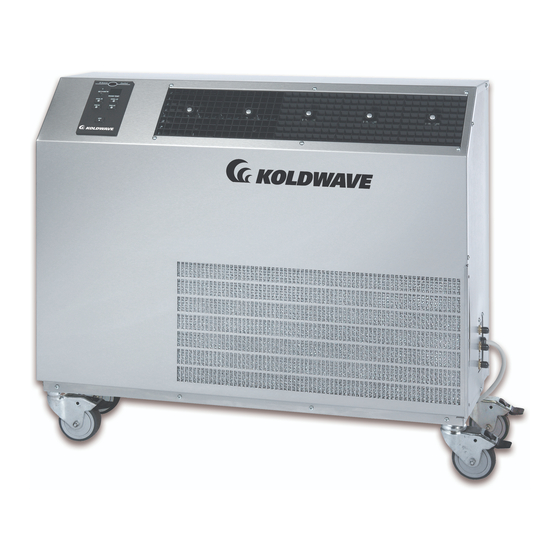
IOM5WK-1
Koldwave 5WK Installation, Operation, & Maintenance Manual
ATTENTION: READ THIS MANUAL AND ALL LABELS ATTACHED TO THE UNIT
CAREFULY BEFORE ATTEMPTING TO INSTALL, OPERATE OR SERVICE
THESE UNITS. CHECK DATA PLATES FOR ELECTRICAL SPECIFICATIONS
AND MAKE CERTAIN THAT THESE AGREE WITH THOSE AT THE POINT OF
INSTALLATION. RECORD THE UNIT MODEL AND SERIAL NUMBER IN THE
SPACE PROVIDED. RETAIN THIS DOCUMENT FOR FUTURE REFERENCE.
Model No._______________________ Serial No._______________________________
IMPROPER INSTALLATION, ADJUSTMENT, ALTERATION, SERVICE OR
MAINTENANCE CAN CAUSE PROPERTY DAMAGE, INJURY OR DEATH. THIS
APPLIANCE MUST BE INSTALLED BY A LICENSED CONTRACTOR OR
QUALIFIED SERVICE PERSONNEL. READ THESE INSTALLATION, OPERATING
AND MAINTENANCE INSTRUCTIONS THOROUGHLY BEFORE INSTALLING OR
SERVICING THE UNIT.
WARNING: INSTALL, OPERATE AND MAINTAIN UNIT IN ACCORDANCE WITH
MANUFACTURER'S INSTRUCTIONS TO AVOID ANY DETERING FACTORS
THAT MAY CAUSE PERSONAL INJURY OR PROPERTY DAMAGE.
INSTALLER'S RESPONSIBILITY: THIS EQUIPMENT HAS BEEN RUN TESTED
AND INSPECTED THOROUGHLY. IT HAS BEEN SHIPPED FREE FROM
DEFECTS FROM OUR FACTORY. HOWEVER, DURING SHIPMENT AND
INSTALLATION, PROBLEMS SUCH AS LOOSE WIRES, LEAKS, OR LOOSE
FASTENERS MAY OCCUR. IT IS THE INSTALLER'S RESPONSIBILITY TO
INSPECT AND CORRECT ANY PROBLEMS THAT MAY BE FOUND.
1
Advertisement
Table of Contents
Troubleshooting

Related Manuals for Koldwave 5WK Series


Summary of Contents for Koldwave 5WK Series
- Page 1 IOM5WK-1 Koldwave 5WK Installation, Operation, & Maintenance Manual ATTENTION: READ THIS MANUAL AND ALL LABELS ATTACHED TO THE UNIT CAREFULY BEFORE ATTEMPTING TO INSTALL, OPERATE OR SERVICE THESE UNITS. CHECK DATA PLATES FOR ELECTRICAL SPECIFICATIONS AND MAKE CERTAIN THAT THESE AGREE WITH THOSE AT THE POINT OF INSTALLATION.
-
Page 2: Table Of Contents
IOM5WK-1 Table of Contents: GENERAL INFORMATION ...................... 4 MODEL CONFIGURATION...................... 5 INSTALLATION INSTRUCTIONS ..................6 ....................... 6 LECTRICAL EQUIREMENTS ......................6 ATER ITTING OCATION SPECIFICATION AND ELECTRIC DATA ................8 SERVICEABILITY ........................9 5WK07 U ................. 9 ONSTRUCTION 5WK07 U ................. - Page 3 IOM5WK-1 5WK07, 5WK14 115V/1 PH ..................... 25 5WK18, 5WK23, 5WK26 208-230V 1 PH ................26 5WK36 208-230V/1PH ......................27 TROUBLE SHOOTING GUIDE ....................28 TROUBLE SHOOTING GUIDE CONTINUED ..............29 TROUBLE SHOOTING GUIDE CONTINUED ..............30 TROUBLE SHOOTING GUIDE CONTINUED ..............31 TROUBLE SHOOTING GUIDE CONTINUED ..............
-
Page 4: General Information
50°F. Doing so could reduce the specified heating capacity and Koldwave 5WK Series Air Conditioners and may cause the freeze control to cycle the Heat Pumps are portable, water-cooled units... -
Page 5: Model Configuration
Code Field 1,2,3 12,13 1,2,3 – MODEL (MD) 5AK – Air Cooled Portable 5WK - Water Cooled Portable 4,5 – UNIT SIZE (US) AK – Air Cooled Models 14 – 11,000 Btuh 18 – 18,300 Btuh 30 – 28,100 Btuh 39 –... -
Page 6: Installation Instructions
208-230/1/60 6 – 20P receive from your Koldwave unit. Electrical Requirements Some Koldwave units are equipped with LCDI device service cords. The service Check the power supply to make certain it is cords employed have plug configurations within 10% of the voltage listed on the data and receptacle requirements as shown in the plate located on the back of the unit. - Page 7 Figure A Water lines should be securely attached to the water valve plate fittings. This is easily accomplished through the quick connect hose kit provided with the unit. Note: The water connections must be made as shown in Figure A. The unit will not operate properly if the connections are not in the correct orientation.
-
Page 8: Specification And Electric Data
Specification and Electric Data ELECTRIC DATA Voltage/Phase/Hertz 115/1/60 115/1/60 230/1/60 Amperage 11.6 Fuse Size (Amps) Watts 1107 1471 REFRIGERANT CHARGE R410A (Ounces) WATER SUPPLY Minimum Water Pressure (PSI) 40.5 UNIT DIMENSIONS (INCHES) Height with Casters 17.63 31.5 31.5 Height without Casters 29.13 29.13 Width... -
Page 9: Serviceability
Serviceability The Koldwave unit has removable panels to provide full service accessibility. 5WK07 Unit Construction Back View Blower Wheel Housing Blower Motor Evaporator Coil Capacitor Suction Service Condenser Access Coil Condenser Water Water Outlet Regulating Valve Condenser Condensate Water Inlet... -
Page 10: 5Wk07 Unit Construction Side View
5WK07 Unit Construction Side View Compressor Contactor Transformer Discharge Service Access Hard Start Assembly Accumulator Compressor... -
Page 11: 5Wk14 Unit Construction Front View
5WK14 Unit Construction Front View Blower Evaporator Motor Coil Blower Wheel Housing Control Panel Condensate Drain Tube Compressor Condenser Coil Temperature Sensor Discharge Water Service Regulating Access Valve... -
Page 12: 5Wk14 Heat Pump Unit Construction Front View
5WK14 Heat Pump Unit Construction Front View Discharge Water Bypass Service Valve Access Reversing Valve Accumulator Condenser Coil Water Strainer Regulating Valve... -
Page 13: 5Wk14 Heat Pump Unit Construction Back View
5WK14 Heat Pump Unit Construction Back View Water Bypass Valve Reversing Valve Discharge Service Access Condensate Compressor Pump... -
Page 14: 5Wk18 Unit Construction Back View
5WK18 Unit Construction Back View Blower Blower Motor Wheel Housing Discharge Service Access Suction Service Access Compressor & Accumulator Condenser Coil Evaporator Coil Water Regulating Valve... -
Page 15: 5Wk18 Unit Construction Side View
5WK18 Unit Construction Side View Hard Start Assembly Compressor Relay Capacitor Suction Service Access Discharge Service Access Compressor Accumulator... -
Page 16: 5Wk23/26 Unit Construction Back View
5WK23/26 Unit Construction Back View Blower Blower Wheel Motor Housing Compressor & Accumulator Condenser Water Coil Regulating Evaporator Valve Coil... -
Page 17: 5Wk23/26 Unit Construction Left View
5WK23/26 Unit Construction Left View Hard Start Assembly Discharge Service Access Transformer Reversing Valve Suction Service Compressor Access Condensate Pump Accumulator... -
Page 18: 5Wk36 Unit Construction Back View
5WK36 Unit Construction Back View Blower Motor Capacitor Blower Blower Wheel Motor Housing Compressor Condenser Coil Water Evaporator Regulating Coil Valve... -
Page 19: 5Wk36 Unit Construction Left View
5WK36 Unit Construction Left View Transformer Contactor Potential Relay Start Capacitor Capacitor Discharge Service Access Suction Service Access Compressor Reversing Valve... -
Page 20: Unit Operation
Heating Hi (Heat Pump Unit): Unit Operation Depress the HEAT HIGH button; the unit will be in the heating mode depending on Unit Power On: the thermostat reading. The reversing valve Plug in the unit to the power source. The will operate to prompt the heat pump mode. -
Page 21: Compressor Off Time
heating mode, the compressor will only be When E.F, or E.S alarm is present, the energized if the temperature is at least 2 Power LED will blink, signaling that the degrees below the set point, and de- alarm condition is present, and the unit will energized once the temperature rises 2 lock out. - Page 22 AC Unit Control Panel Optional Remote Control Heat Pump Unit Control Panel...
-
Page 23: Inspection And Repair Of Electrical System
Service other than routine maintenance should be performed only by a qualified refrigeration Preventative Maintenance service person. Your Koldwave portable spot cooler has Always disconnect power and discharge been designed to give maximum capacitors before servicing. performance and reliability with minimum maintenance. -
Page 24: Unit Storage
as follows: 1. Soak filter in solution of warm water and Do not use if the pump or its cable is detergent for 15 minutes. damaged in any way. Protect the cable and 2. Rinse in clean, hot water and shake excess tubing from sharp edges. -
Page 25: Electrical Diagram
Electrical Diagram 5WK07, 5WK14 115V/1 PH... -
Page 26: 5Wk18, 5Wk23, 5Wk26 208-230V 1 Ph
5WK18, 5WK23, 5WK26 208-230V 1 PH... -
Page 27: 5Wk36 208-230V/1Ph
5WK36 208-230V/1PH... -
Page 28: Trouble Shooting Guide
Trouble Shooting Guide Before troubleshooting this system, read this manual to determine electrical power and installation requirements to allow the spot cooler to perform at its maximum efficiency. Refer to general description, wiring diagrams and photographs to get an understanding of how the unit functions. -
Page 29: Trouble Shooting Guide Continued
Trouble Shooting Guide Continued GENERAL TROUBLESHOOTING Abnormal noise. 1 Loose compressor mounting nuts. 1 Tighten. 2 Defective, improper or worn rubber 2 Replace grommets. grommets on the compressor mounting bolts. 3 Copper tube vibrating. 3 Adjust by bending slightly to firm position. Separate tubes touching cabinet or each other. -
Page 30: Trouble Shooting Guide Continued
Trouble Shooting Guide Continued GENERAL TROUBLESHOOTING Circuit breaker or fuses blowing 1 Low voltage to unit. 1 Check power supply for proper voltage at unit plus or minus 10% of rated nameplate voltage. 2 Compressor short cycles 2 See section on compressor troubleshooting. 3 Defective wiring or connection. -
Page 31: Trouble Shooting Guide Continued
Trouble Shooting Guide Continued COMPRESSOR TROUBLESHOOTING Compressor tries to start when t- 1 Low voltage 1 Check voltage at wall outlet. Must be within stat closes, but cuts out on 10% of nameplate rating voltage. overload; finally starts after several attempts 2 Compressor capacitor incorrect or defective 2 Check capacitance and replace if necessary. -
Page 32: Trouble Shooting Guide Continued
Trouble Shooting Guide Continued COMPRESSOR TROUBLESHOOTING Compressor short cycles 1 Low voltage 1 Check voltage at wall outlet. Must be within 10% of nameplate rating voltage. 2 Capacitor incorrect or defective 2 Check capacitance and replace if necessary. 3 Compressor motor defective 3 Replace compressor 4 Wiring incorrect or defective 4 Tug on wires to see if they will separate from connections. -
Page 33: Trouble Shooting Guide Continued
Trouble Shooting Guide Continued HEAD PRESSURE TROUBLESHOOTING Too high 1 Condenser dirty, clogged or restricted. 1 Replace condenser coil. 2 Air or non-condensable gases in system 2 Recover refrigerant, install filter/dryer, evacuate system and weigh in proper charge of virgin refrigerant. 3 Fan blade or motor defective 3 Check and replace. - Page 34 4830 Transport Drive Dallas, TX 75247 214-638-6010 T 214-905-0806 F www.koldwave.com www.mestekparts.com Rev Date: 080510...
Need help?
Do you have a question about the 5WK Series and is the answer not in the manual?
Questions and answers