Table of Contents
Advertisement
Quick Links
Installation Guide
Color CCTV Camera
WV-CW324LE
Model No:
WV-CW314LE
WV-CW304LE
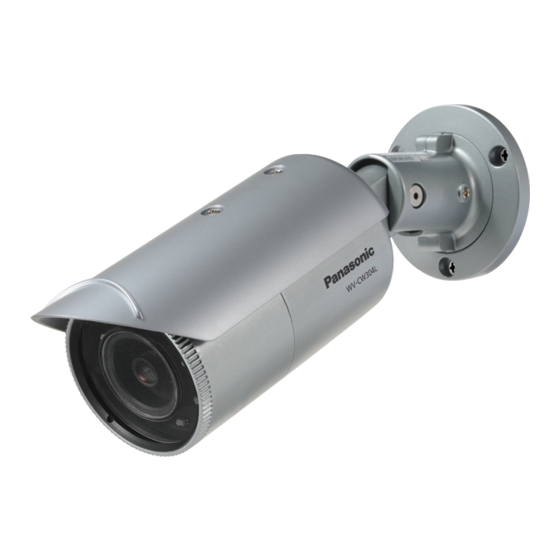
This illustration represents WV-CW324LE, WV-CW314LE, WV-CW304LE.
Before attempting to connect or operate this product,
please read these instructions carefully and save this manual for future use.
The model number is abbreviated in some descriptions in this manual.
Advertisement
Table of Contents

Subscribe to Our Youtube Channel
Related Manuals for i-PRO WV-CW304L


Summary of Contents for i-PRO WV-CW304L
- Page 1 Installation Guide Color CCTV Camera WV-CW324LE Model No: WV-CW314LE WV-CW304LE This illustration represents WV-CW324LE, WV-CW314LE, WV-CW304LE. Before attempting to connect or operate this product, please read these instructions carefully and save this manual for future use. The model number is abbreviated in some descriptions in this manual.
- Page 2 We declare under our sole responsibility that the Wij verklaren als enige aansprakelijke, dat het product to which this declaration relates is in product waarop deze verklaring betrekking heeft, conformity with the standard or other normative voldoet aan de volgende norm of ander normatief document following the provisions of Directive dokument, overeenkomstig de bepalingen van 2004/108/EC.
-
Page 3: Table Of Contents
Contents Important safety instructions ......................4 Limitation of liability ......................... 5 Disclaimer of warranty ........................5 Preface ............................6 About notations ..........................6 Features ............................6 About the user manuals ........................7 Trademarks and registered trademarks ................... 7 Precautions ............................ 8 Precautions for installation ...................... -
Page 4: Important Safety Instructions
Important safety instructions 1) Read these instructions. 2) Keep these instructions. 3) Heed all warnings. 4) Follow all instructions. 5) Do not block any ventilation openings. Install in accordance with the manufacturer's instruc- tions. 6) Do not install near any heat sources such as radiators, heat registers, stoves, or other appara- tus (including amplifiers) that produce heat. -
Page 5: Limitation Of Liability
IMPROVEMENTS OF THIS PUBLICATION AND/OR THE CORRESPONDING PRODUCT (S). Disclaimer of warranty IN NO EVENT SHALL i-PRO Co., Ltd. BE LIABLE TO ANY PARTY OR ANY PERSON, EXCEPT FOR REPLACEMENT OR REASONABLE MAINTENANCE OF THE PRODUCT, FOR THE CASES, INCLUDING BUT NOT LIMITED TO BELOW:... -
Page 6: Preface
Preface This product is a 1/3-type CCD D/N infrared CCTV camera. Connection of this product to a video monitor allows users to use this product as a monitoring camera. • WV-CW324LE, WV-CW314LE: with function of color/black-and-white mode switch and back focus adjustment. -
Page 7: About The User Manuals
Note: • The VMD function is not the dedicated function to prevent thefts, fires, etc. We are not responsible for any accidents or damages caused by applying the function for the above purposes. About the user manuals The operating instructions of the camera consist of 2 sets: this book and operating instructions (PDF). -
Page 8: Precautions
Precautions Refer installation work to the dealer. Avoid installing this product in locations where it is subject to damage by salt or Installation work requires technique and corrosive gas. experiences. Otherwise injury or damage to this product may result. Otherwise the mounting fixtures will deterio- Be sure to consult the dealer. - Page 9 The measures of protection against Do not touch the front cover (transparent snowfall shall be taken. cover) with your bare hands. In areas where lots of snow accumulates, the A dirty cover causes deterioration of picture weight of snow may cause the product to fall quality.
- Page 10 Cleaning this product body Turn the power off when cleaning this product. Do not use strong abrasive detergent when cleaning this product. Otherwise, it may cause discoloration. When using a chemical cloth for cleaning, read the caution provided with the chemical cloth product.
-
Page 11: Precautions For Installation
Precautions for installation i-PRO Co., Ltd. assumes no responsibility Avoid installing and connecting during a for injuries or property damage resulting lightning storm. Otherwise, an electric from failures arising out of improper shock or fire may be caused. installation or operation inconsistent with this documentation. - Page 12 Radio interference When the camera is used near T V/radio antenna, strong electric field or magnetic field (near a motor or a transformer), images may b e d i s to r te d a n d n o i s e s o u n d m ay b e produced.
-
Page 13: Major Operating Controls
Major operating controls Safety wire Camera mount Sunshield bracket Video output connector Power cord Yow lock screw Front cover Panning lock screw Tilting lock Rear cover screw <WV-CW324LE, WV-CW314LE> Packing IR LED Lens Monitor output button jack... -
Page 14: Preparations
<WV-CW304LE> Set button IR LED Packing Lens Monitor output jack Preparations The camera can be directly mounted on the wall or ceiling. Important: • Prepare the mounting screws according to the material of the area where the camera mount bracket is to be installed. In this case, wood screws and nails should not be used. Recom- mended tightening torque M4: 1.60 N·m {1.18 lbf·ft} •... -
Page 15: Installation
Installation Affix the installation template label (accessory) to the ceiling or wall, and use a pen to mark the positions of the screws and cable mounting hole in the ceiling or wall. Remove the installation template label and attach the camera with 3 screws (locally procured). Installation template label φ... -
Page 16: Connections
Connections Connect the video output Important: Video output Power cord connector • Be sure to turn off the power of each device before connecting. • Be sure to secure the coaxial cable connectors. Connect a coaxial cable (locally procured) to the video output connector. - Page 17 12 V DC Calculation of the relation among the cable length, resistance, and power supply. The voltage supplied to the camera shall be between 10.8 V DC and 16 V DC. 10.8 V DC ≤ V - 2 (R x I x L) ≤ 16 V DC L : Cable length (m) Ω...
-
Page 18: Adjustment
Adjustment Be sure to view the monitor for adjustment when the camera angle is adjusted. Supply power to this unit, connect the monitor for adjustment (e.g. a small LCD) to the monitor output jack, and adjust the camera angle (turn off the power after view angle adjustment for safety). - Page 19 Important: • This video output is intended for confirmation of view angle, etc. during installation or repair service, and not for recording or monitoring. Note: • Monitor output jack has higher priority than video output connector. Video cannot be output through the video output cable after connecting the adjustment monitor.
- Page 20 Note: • Do not put your fingers on the movable part where the safety warning label is pasted when the camera angle is adjusted, unless your hands will be clamped when the front portion of camera hangs down. • Use a hexagonal wrench with width across flats of 3 mm (locally procured) to loosen or tighten the yow lock screw, panning lock screw and tilting lock screw.
- Page 21 Note: • The ABF function is not available over the entire focus range. Be sure to perform approximate adjustment of the view angle before manual focusing, and then press the [ABF] button to enable the ABF function. • For the following subjects, select ELC control method, and then manually adjust the focus. •...
-
Page 22: Setup Menu
Setup menu Performing each setting item in the setup menu should be completed in advance to use this unit. Perform the settings for each item in accordance with the installation conditions and customer requirements. List of setup menu Setup item Description CAMERA ID This item specifies the camera title. -
Page 23: Basic Operation
Basic operation The operations in the setup menu are performed with the operation buttons after calling up the setup menu on the connected video monitor. The description below explains how to operate the setup menu basically. Screenshots of WV-CW324LE are shown as an example. Screenshot 1 Hold down the [SET] button for about 2 Step 1... - Page 24 Screenshot 3 The selected setup screen in the setup menu Step 4 appears on the screen. Perform the settings for each item. **CAMERA SETUP** • Selection of setting item: SCENE1 ALC/ELC Press the [UP] or [DOWN] button to move SHUTTER the cursor.
-
Page 25: Cw324L
Screen transition diagram CW324L Top screen “CAMERA ID” screen CW304L MODEL WV-CW324L **CAMERA ID** CW314L CAMERA ID 0123456789 CAMERA ABCDEFGHIJKLM SYSTEM NOPQRSTUVWXYZ BACK-FOCUS ().,'":;&#!?= SPECIAL +-*/%$ LANGUAGE SPACE POSI RET TOP END RESET ....SETUP DISABLE “CAMERA SETUP” screen **CAMERA SETUP** SCENE1 ALC/ELC SHUTTER... - Page 26 CW324L CW304L Screen transition diagram CW314L Top screen “CAMERA ID” screen MODEL WV-CW314L **CAMERA ID** CAMERA ID 0123456789 CAMERA ABCDEFGHIJKLM SYSTEM NOPQRSTUVWXYZ BACK-FOCUS ().,'":;&#!?= SPECIAL +-*/%$ LANGUAGE SPACE POSI RET TOP END RESET ....SETUP DISABLE “CAMERA SETUP” screen **CAMERA SETUP** SCENE1 ALC/ELC SHUTTER...
- Page 27 CW324L Screen transition diagram CW304L Top screen “CAMERA ID” screen CW314L MODEL WV-CW304L **CAMERA ID** CAMERA ID 0123456789 CAMERA ABCDEFGHIJKLM SYSTEM NOPQRSTUVWXYZ SPECIAL ().,'":;&#!?= LANGUAGE +-*/%$ SPACE POSI RET TOP END RESET ....SETUP DISABLE “CAMERA SETUP” screen **CAMERA SETUP**...
-
Page 28: Troubleshooting
Troubleshooting Before asking for repairs, confirm the causes with the following table. Contact your dealer if a problem cannot be solved even after checking and trying the solution in the table or a problem is not described below. Cause/solution Reference page Symptom •... -
Page 29: Specifications
Specifications General WV-CW324LE WV-CW314LE WV-CW304LE Power source and 24 V AC: 3.2 W, 24 V AC 50/60 Hz: 5.2 W, 12 V DC: 560 mA power consumption 12 V DC: 320 mA Image sensor 1/3-type interline transfer CCD Effective pixels 976 (H) ×... -
Page 30: Standard Accessories
WV-CW324LE WV-CW314LE WV-CW304LE Digital noise reduction LOW/HIGH Day&Night (IR) AUTO1/AUTO2/ON/OFF IR LED irradiation distance 50 m 20 m IR LED lights OFF/AUTO/FIX Video motion detection OFF/MOTION DETECTION/SCENE CHANGE Number of scene file Privacy zone ON (1)/ON (2)/OFF Image stabilizer ON/OFF Electronic zoom ON (up to 2x)/OFF Upside-down... - Page 31 Information on Disposal for Users of Waste Electrical & Electronic Equipment (private households) This symbol on the products and/or accompanying documents means that used electrical and electronic products should not be mixed with general household waste. For proper treatment, recovery and recycling, please take these products to designated collection points, where they will be accepted on a free of charge basis.
- Page 32 For U.S. and Canada: i-PRO Americas Inc. For Europe and other countries: i-PRO EMEA B.V. https://www.i-pro.com/ © i-PRO Co., Ltd. 2022 sL0313-4042 PGQX1305VA Printed in China...
Need help?
Do you have a question about the WV-CW304L and is the answer not in the manual?
Questions and answers