Table of Contents
Advertisement
Quick Links
Advertisement
Table of Contents

Related Manuals for Black Box G.SHDSL NTU LB510A


Summary of Contents for Black Box G.SHDSL NTU LB510A
- Page 1 LB510A G.SHDSL NTU Getting Started Guide...
- Page 2 Radio and TV Interference This equipment generates and uses radio frequency energy, and if not installed and used properly—that is, in strict accordance with the manufacturer's instructions—may cause interference to radio and television recep- tion. This equipment has been tested and found to comply with the limits for a Class A computing device in accordance with the specifications in Subpart B of Part 15 of FCC rules, which are designed to provide reason- able protection from such interference in a commercial installation.
- Page 3 FCC Part 68 Compliance Statement This equipment complies with Part 68 of FCC rules and the requirements adopted by ACTA. On the bottom side of this equipment is a label that contains—among other information—a product identifier in the format US: AAAEQ##TXXXX . If requested, this number must be provided to the telephone company. The method used to connect this equipment to the premises wiring and telephone network must comply with the applicable FCC Part 68 rules and requirements adopted by the ACTA.
- Page 4 El aparato eléctrico no deberá ser usado cerca del agua—por ejemplo, cerca de la tina de baño, lavabo, sótano mojado o cerca de una alberca, etc. El aparato eléctrico debe ser usado únicamente con carritos o pedestales que sean recomendados por el fabricante.
- Page 5 Summary Table of Contents General Introduction............................. 14 Initial Configuration ............................. 16 G.SHDSL Config and Status......................... 21 Ethernet & WAN PPP Config and Status ..................... 27 Installation & operation..........................31 System Management............................35 Diagnostic Tools ............................39 Specifications ..............................41 RJ-11 non-shielded DSL port ........................
-
Page 6: Table Of Contents
Table of Contents Audience................................11 Structure................................11 Precautions ................................12 Safety when working with electricity .......................12 General observations ............................13 Typographical conventions used in this document....................13 General conventions ............................13 General Introduction............................. 14 LB510A Overview ..............................15 Features .................................15 Initial Configuration ............................. 16 Introduction ................................17 Power up the NTU... - Page 7 LB510A Getting Started Guide Table of Contents Operation................................32 Power-up................................32 LED status indicators ............................33 Power (Yellow) ..............................33 WAN LEDs ..............................33 Link (Yellow) ............................33 Tx (Yellow) ...............................33 Rx (Yellow) ...............................33 Ethernet LEDs ..............................33 Link (Yellow) ............................33 100M (Yellow) ............................34 Tx (Yellow) ...............................34 Rx (Yellow) ...............................34 System...
- Page 8 LB510A Getting Started Guide Table of Contents Power ..................................44 G.SHDSL Physical connection & Transmission Line ..................44 Line Coding ..............................44 Line Interface ................................44 Environment .................................44 Dimensions ................................44 RJ-11 non-shielded DSL port ........................45 RJ-11 non-shielded DSL port..........................46 RJ-45 shielded 10/100 Ethernet port ......................
- Page 9 List of Figures Model LB510A ............... . . 15 Model LB510A .
- Page 10 List of Tables General conventions ..............13...
-
Page 11: Audience
About this guide This guide describes installing and operating the Black Box Model LB510A G.SHDSL NTU. Audience This guide is intended for the following users: • Operators • Installers • Maintenance technicians Structure This guide contains the following chapters and appendices: •... -
Page 12: Precautions
Do not work on the system or connect or disconnect cables during periods of lightning activity. WARNING This device contains no user serviceable parts. The equipment shall be returned to Black Box for repairs, or repaired by qualified service personnel. WARNING... -
Page 13: General Observations
LB510A Getting Started Guide The external AC adaptor shall be a listed limited power source that incorporates a disconnect device and shall be positioned within easy reach of the operator. Ensure that the AC power WARNING cable meets all applicable standards for the country in which it is to be installed, and that it is connected to a wall outlet which has earth ground. -
Page 14: General Introduction
Chapter 1 General Introduction Chapter contents LB510A Overview ..............................6 Features ...................................6... -
Page 15: Lb510A Overview
1 • General Introduction LB510A Overview The Black Box Model LB510A G.SHDSL NTU provides high speed 2-wire connectivity to ISPs, PTTs, and enterprise environments using Symmetrical High-data-rate Digital Subscriber Line (G.SHDSL) technology. The Model LB510A provides a 10/100BaseT Ethernet interface on a shielded RJ-45 jack, the DSL on an RJ- 11 jack, and the RS-232 console port on an RJ-45 jack. - Page 16 Chapter 2 Initial Configuration Chapter contents Introduction ................................8 Power up the NTU ..............................8 AC power-up ..............................8 Power-up indication ............................8 Configure the IP address............................8 Connect a PC and log in ...........................9 Modify the IP address ............................9 Connect to the local IP network ........................10 Log onto the web management interface ......................10...
-
Page 17: Initial Configuration
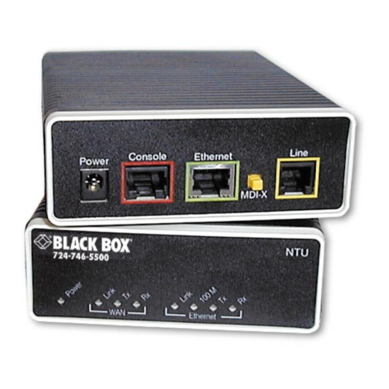
LB510A Getting Started Guide 2 • Initial Configuration Introduction The Model LB510A (see figure 2) has two configuration modes: RS-232 console and web page GUI software. Figure 2. Model LB510A The RS-232 console is used for the initial configuration of the IP address and mask. Subsequently the easiest method is to use a standard web browser to complete the configuration. -
Page 18: Connect A Pc And Log In
LB510A Getting Started Guide 2 • Initial Configuration Connect a PC and log in Using the included combination RS-232/Ethernet cable and DB9-RJ45 adapter, connect a PC’s serial port to the NTU ’s Console port (red outline) (see figure The interconnecting cables shall be acceptable for external use and shall be rated for the proper application with respect to volt- age, current, anticipated temperature, flammability, and mechanical serviceability. -
Page 19: Connect To The Local Ip Network
LB510A Getting Started Guide 2 • Initial Configuration Connect to the local IP network Now you can connect the G.SHDSL NTU to your local IP network and complete the remaining configura- tion from your PC using a standard web browser. Connect the G.SHDSL NTU’s Ethernet port (green) to the same Ethernet segment as your PC (see figure The front-panel Ethernet Link LED should turn on. -
Page 20: Connect The G.shdsl Port
LB510A Getting Started Guide 2 • Initial Configuration Connect the G.SHDSL port 3. Obtain single-twisted-pair cable with an RJ-11 plug connector at each end. 4. Plug one end of the cable into the (yellow) RJ-11 socket (labelled Line) on the G.SHDSL NTU. (See figure 5. -
Page 21: G.shdsl Config And Status
Chapter 3 G.SHDSL Config and Status Chapter contents configuration..............................13 DSL Parameters ..............................13 DSL Error Monitor Configuration ........................14 G.SHDSL Status ..............................15 Run-Time Statistics ............................15 DSL Line Error Counters ..........................16 Local Interface Error Counters ........................16 Clearing Error Counters ..........................17... -
Page 22: Dsl Configuration
LB510A Getting Started Guide 3 • G.SHDSL Config and Status DSL configuration By going to the Configuration hyperlink in the Configuration Menu, you can configure the DSL link to specific parameters if the LB510A is not used in the Plug ‘n’ Play mode. They are listed as follows. Note After changing the parameters in the DSL Configuration section of the web page, they take immediate effect upon clicking the Configure button. -
Page 23: Dsl Error Monitor Configuration
LB510A Getting Started Guide 3 • G.SHDSL Config and Status DSL Error Monitor Configuration The DSL Error Monitor provides various statistics for the DSL line. The monitor parameters are configured here. The error counters are also cleared from this menu. Figure 8. -
Page 24: G.shdsl Status
LB510A Getting Started Guide 3 • G.SHDSL Config and Status G.SHDSL Status Selecting the Status hyperlink on the Configuration Menu provides the web page containing the G.SHDSL sta- tus and the Bridged PPP link status. The G.SHDSL Status is divided into three groups, Run-Time Statistics, DSL Line Error Counters, and Local Interface Error Counters. -
Page 25: Dsl Line Error Counters
LB510A Getting Started Guide 3 • G.SHDSL Config and Status DSL Line Error Counters Five counters display how many Loss of Sync’s have occurred, CRC Errors, SEGD Errors, SEGA Errors, and Loss of Delineation. Loss of Sync and CRC Errors are the most commonly used statistics in normal performance evaluation. -
Page 26: Clearing Error Counters
LB510A Getting Started Guide 3 • G.SHDSL Config and Status Clearing Error Counters The error counters may be cleared in the Configuration web page or here in the Status web page. Select Clear All Counters and click on the Submit button. Figure 12. -
Page 27: Ethernet & Wan Ppp Config And Status
Chapter 4 Ethernet & WAN PPP Config and Status Chapter contents IP configuration ..............................19 PPP configuration ..............................19 Ethernet port configuration ...........................19 Ethernet Basic Port Attributes .........................19 Ethernet Advanced Port Attributes ........................20... -
Page 28: Ip Configuration
LB510A Getting Started Guide 4 • Ethernet & WAN PPP Config and Status IP configuration The most commonly used technique for changing the IP address and subnet mask is in the initial configura- tion via the console port. However you can also change the IP address in the web GUI pages. In the Configu- ration web pages is located the section for changing these two parameters. -
Page 29: Ethernet Advanced Port Attributes
LB510A Getting Started Guide 4 • Ethernet & WAN PPP Config and Status Figure 15. Ethernet performance statistics Ethernet Advanced Port Attributes While in the page for the Ethernet Basic Port Attributes, click on View advanced attributes… to view many additional parameters which include three configurable variables—Auto negotiation, 100Base-TX operation, and Full-duplex. - Page 30 LB510A Getting Started Guide 4 • Ethernet & WAN PPP Config and Status Figure 17. Configurable Ethernet parameters Ethernet port configuration...
-
Page 31: Installation & Operation
Chapter 5 Installation & operation Chapter contents Installation ................................23 Connecting the twisted-pair interface ......................23 Operation................................23 Power-up................................23 LED status indicators ............................24 Power (Yellow) ..............................24 WAN LEDs ..............................24 Link (Yellow) ............................24 Tx (Yellow) ...............................24 Rx (Yellow) ...............................24 Ethernet LEDs ..............................24 Link (Yellow) ............................24 100M (Yellow) ............................25... -
Page 32: Installation
The Model LB510A powers up as soon as it is plugged into an AC outlet—there is no power switch. There are no user-serviceable parts in the power supply section of the Model LB510A. Fuse replacement should only be performed by qualified service per- sonnel. Contact Black Box Technical support at (724) 746-5500 for more WARNING information. -
Page 33: Led Status Indicators
LB510A Getting Started Guide 5 • Installation & operation LED status indicators There are eight LEDs that provide information on the state of the unit. Figure 18 shows the location of the front panel LEDs. Following figure 18 is a description of each LED’s function. ™... -
Page 34: 100M (Yellow)
LB510A Getting Started Guide 5 • Installation & operation 100M (Yellow) The Link LED glows solid if the 100Mbps Ethernet link has been negotiated. If there is not Ethernet connec- tion, the LED defaults to on to indicate that the Ethernet port is ready to operate in 100Base-TX mode. Tx (Yellow) The Link LED flashes upon transmitting data out the Ethernet port. -
Page 35: System Management
Chapter 6 System Management Chapter contents Saving the configuration ............................27 Reset for Factory Default............................27 Console ................................27 Backing up and restoring saved configurations.......................28 Authentication...............................28 System Software Upgrade ..........................29... -
Page 36: Saving The Configuration
LB510A Getting Started Guide 6 • System Management Saving the configuration To save all configuration changes into non-volatile memory, click on the hyperlink Save Configuration in the System Management menu item. Click on the Save button and wait until you see the message that verifies the save was executed properly. -
Page 37: Backing Up And Restoring Saved Configurations
LB510A Getting Started Guide 6 • System Management Backing up and restoring saved configurations At times you may want to store the completed configuration of your LB510A on a PC so you can return to a working configuration easily. Click on the Backup/Restore Configuration hyperlink under the System Manage- ment menu. -
Page 38: System Software Upgrade
LB510A Getting Started Guide 6 • System Management System Software Upgrade Over the course of time, new software is released. Also found on the System Management menu is the hyperlink Software Upgrade. Figure 23. Upgrading software on the LB510A Click on the Browse… button to find and select the desired software version on your PC. Subsequently click on Update to invoke the upgrade process. -
Page 39: Diagnostic Tools
Chapter 7 Diagnostic Tools Chapter contents LED status monitor & definition ..........................32 System tools for testing............................32 Ping & Traceroute ............................32 Clearing error counters ...........................32... -
Page 40: Led Status Monitor & Definition
LB510A Getting Started Guide 7 • Diagnostic Tools LED status monitor & definition See LED status indicators in “LED status indicators” on page 33. System tools for testing Testing and troubleshooting can utilize a broad range of tools. Various types of tools are a part of the LB510A capabilities, from observing the LED’s status, tracking the error counters, and using network tools which are described in this section. - Page 41 Appendix A Specifications Chapter contents General characteristics ............................34 G.SHDSL characteristics ............................34 Ethernet ................................34 Protocol support..............................34 Management .................................35 10Base-T/100Base-TX interface ..........................35 Serial connector ..............................35 Diagnostics................................35 Status LEDs................................35 Power ................................35 WAN Link ..............................35 WAN Tx ................................35 WAN Rx .................................35 Ethernet Link ..............................35 Ethernet 100M ...............................36 Ethernet Tx...
-
Page 42: A Specifications
LB510A Getting Started Guide A • Specifications General characteristics • Compact low-cost Plug ‘n’ Play NTU • 10/100 Ethernet port • Unlimited host support • Comprehensive hardware diagnostics, independent of operating system, easy maintenance and effortless installation • Built-in web configuration •... -
Page 43: Management
LB510A Getting Started Guide A • Specifications Management • Web-based configuration via embedded web server • CLI menu for configuration, management, and diagnostics • Local (VT-100 or Telnet) • Console port set at 9600 bps, 8 bits, no parity, 1 stop bit, no flow control 10Base-T/100Base-TX interface The Ethernet port is a shielded RJ-45 jack, autonegotiate, full- or half-duplex with an MDI-X switch. -
Page 44: Ethernet 100M
LB510A Getting Started Guide A • Specifications Ethernet 100M The DSL LED glows solid while a DSL link is established. While the DSL link is training it blinks once every second. Ethernet Tx The DSL LED glows solid while a DSL link is established. While the DSL link is training it blinks once every second. -
Page 45: Rj-11 Non-Shielded Dsl Port
Appendix B RJ-11 non-shielded DSL port Chapter contents RJ-11 non-shielded DSL port..........................38... -
Page 46: Non-Shielded Dsl Port
LB510A Getting Started Guide B • RJ-11 non-shielded DSL port RJ-11 non-shielded DSL port Single twisted-pair (TP) for full-duplex transmission. The signals are polarity insensitive. Pin # Signal Ring RJ-11 non-shielded DSL port... -
Page 47: Shielded 10/100 Ethernet Port
Appendix C RJ-45 shielded 10/100 Ethernet port Chapter contents RJ-45 shielded 10/100 Ethernet port........................40... -
Page 48: Shielded 10/100 Ethernet Port
LB510A Getting Started Guide C • RJ-45 shielded 10/100 Ethernet port RJ-45 shielded 10/100 Ethernet port Note The following table assumes the MDI-X switch is in the out position. Pin # Signal TX+ (output) TX- (output) RX+ (input) RX- (input) RJ-45 shielded 10/100 Ethernet port... -
Page 49: Rs-232 Console Interface Pin Assignments
Appendix D RS-232 console interface pin assignments Chapter contents RS-232 console interface pin assignments......................42... -
Page 50: Rs-232 Console Interface Pin Assignments
LB510A Getting Started Guide D • RS-232 console interface pin assignments RS-232 console interface pin assignments RJ-45 non-shielded Connector (EIA-561) Signal DSR (out) CD (out) DTR (in) Signal Ground RD (out) TD (in) CTS (out) RTS (in) RS-232 console interface pin assignments... - Page 51 © Copyright 2007. Black Box Corporation. All rights reserved. Released: February 6, 2007 1000 Park Drive • Lawrence, PA 15055-1018 • 724-746-5500 • Fax 724-746-0746...
Need help?
Do you have a question about the G.SHDSL NTU LB510A and is the answer not in the manual?
Questions and answers