Table of Contents
Advertisement
Quick Links
DECEMBER 2000
IS200A-R2
NTU-1
CUSTOMER
Order toll-free in the U.S.: Call 877-877-BBOX (outside U.S. call 724-746-5500)
SUPPORT
FREE technical support 24 hours a day, 7 days a week: Call 724-746-5500 or fax 724-746-0746
INFORMATION
Mailing address: Black Box Corporation, 1000 Park Drive, Lawrence, PA 15055-1018
Web site: www.blackbox.com • E-mail: info@blackbox.com
Advertisement
Table of Contents

Related Manuals for Black Box NTU-1


Summary of Contents for Black Box NTU-1
- Page 1 Order toll-free in the U.S.: Call 877-877-BBOX (outside U.S. call 724-746-5500) SUPPORT FREE technical support 24 hours a day, 7 days a week: Call 724-746-5500 or fax 724-746-0746 INFORMATION Mailing address: Black Box Corporation, 1000 Park Drive, Lawrence, PA 15055-1018 Web site: www.blackbox.com • E-mail: info@blackbox.com...
- Page 2 FCC INFORMATION FEDERAL COMMUNICATIONS COMMISSION and INDUSTRY CANADA RADIO FREQUENCY INTERFERENCE STATEMENTS This equipment has been tested and found to comply with Class B Digital Device. the limits for a Class B computing device pursuant to Part 15 of the FCC Rules. These limits are designed to provide reasonable protection against harmful interference in a residential installation.
- Page 3 NTU-1 NORMAS OFICIALES MEXICANAS (NOM) ELECTRICAL SAFETY STATEMENT INSTRUCCIONES DE SEGURIDAD 1. Todas las instrucciones de seguridad y operación deberán ser leídas antes de que el aparato eléctrico sea operado. 2. Las instrucciones de seguridad y operación deberán ser guardadas para referencia futura.
- Page 4 NOM STATEMENT 12. Precaución debe ser tomada de tal manera que la tierra fisica y la polarización del equipo no sea eliminada. 13. Los cables de la fuente de poder deben ser guiados de tal manera que no sean pisados ni pellizcados por objetos colocados sobre o contra ellos, poniendo particular atención a los contactos y receptáculos donde salen del aparato.
- Page 5 NTU-1 TRADEMARKS USED IN THIS MANUAL Any trademarks mentioned in this manual are acknowledged to be the property of the trademark owners.
-
Page 6: Table Of Contents
4. Connector Pinouts ......... . 14 4.1 NTU-1 to ISDN U Interface ....... . 14 4.2 NTU-1 to Terminal Endpoint Equipment. -
Page 7: Specifications
NTU-1 1. Specifications Maximum Operating Distance—18,000 ft. (5486 m) U Interface Coding—2B1Q Operating Temperature—32 to 122°F (0 to 50°C) Humidity—Up to 95% noncondensing Power Consumption—5 watts maximum Wallmount Transformer Output—34 VAC Size—1.5"H x 6.3"W x 5.1"D (3.8 x 16 x 13 cm) -
Page 8: Introduction
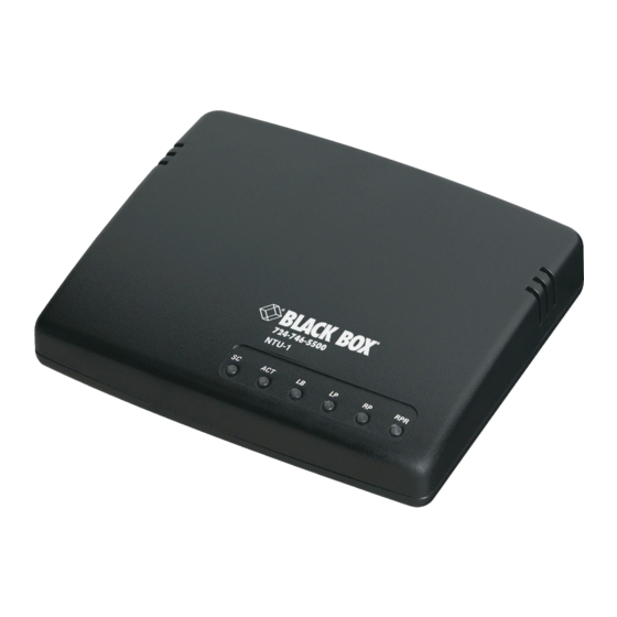
T Interface Figure 2-1. Typical ISDN interface arrangements. The NTU-1 can reside on a desk or be wall mounted. Six light-emitting diodes (LEDs) show unit status. The rear panel houses the power jack, two jacks for either an S or T interface to the customer premise equipment, one U jack for connection to the central office, and one 4-position DIP switch for terminating resistor selection. -
Page 9: Features
NTU-1 • Power supply • This users’ manual 2.3 Features • Mounts on a wall or desktop • Point-to-point or multipoint configuration • Built-in surge protection • All options and connections are accessible via the rear panel • Up to 18,000 feet (5486 m) operating distance •... -
Page 10: Installation And Operation
6 pan-head type screws. Allow the screw heads to protrude ⁄ ". After inserting all three screws, position the NTU-1 in place by engaging the screw heads and sliding it to the right until it’s secure. You might have to adjust the screws for a snug fit. -
Page 11: Dip-Switch Options
NTU-1 3.3 DIP-Switch Options When you install the NTU-1, you must set the terminating resistors to match the applications shown in Figure 3-1. Example #1 Terminal Equipment Up to 1 km 100 ohms 100 ohms Point-to-Point Connection NTU-1 Example #2... - Page 12 CHAPTER 3: Installation and Operation Figure 3-2. DIP-switch location. The factory setting should work for most installations. S/T interface links that have unusual characteristics may experience improved performance by putting resistors in or out of the circuit. The units on the opposite end of the S/T line also have terminating resistors that you must consider.
-
Page 13: Isdn And Terminal Hookup
Connecting the NTU-1 is simple and straightforward. The supplied U cable inserts into the U jack on the NTU-1. The opposite end connects to the ISDN wall jack. Similar cables are used to connect the S/T jacks to the designated terminal endpoint equipment. -
Page 14: Leds
ISDN switch. • ACT (Activity: ON indicates that a link-up between the terminal equipment and ISDN central office via the NTU-1 has been achieved and transmission can take place. If a disruption occurs between the U interface and the ISDN switch, the LED flickers (8 Hz). -
Page 15: Connector Pinouts
(CPE) with standard 8-pin RJ-45 modular connectors. All connections are on the rear panel and are labeled. 4.1 NTU-1 to ISDN U Interface The U jack connects the NTU-1 to the ISDN. Pin functions are shown in Table 4-1. Table 4-1. Pin functions for U jack Function... -
Page 16: Troubleshooting
CHAPTER 5: Troubleshooting 5. Troubleshooting 5.1 Calling Black Box If you determine that your NTU-1 is malfunctioning, do not attempt to alter or repair the unit. It contains no user-serviceable parts. Contact Black Box at 724-746- 5500. Before you do, make a record of the history of the problem. We will be able to... -
Page 17: Appendix. Wallmount Template
NTU-1 Appendix. Wallmount Template Use this template to mount the NTU-1 on the wall. - Page 18 © Copyright 2000. Black Box Corporation. All rights reserved. 1000 Park Drive • Lawrence, PA 15055-1018 • 724-746-5500 • Fax 724-746-0746...
Need help?
Do you have a question about the NTU-1 and is the answer not in the manual?
Questions and answers