Table of Contents
Advertisement
Quick Links
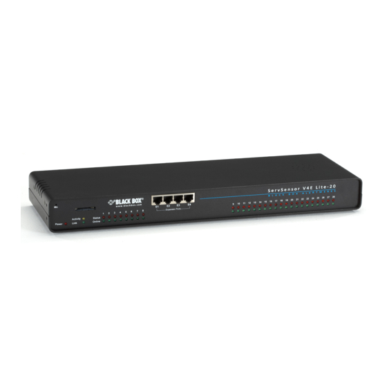
ServSensor V4E Lite with 20 or 60 VAC or VDC Dry Contacts
Use this intelligent environmental monitoring
device to identify problems before they disrupt
your equipment.
Features an embedded Web server and Linux operating system.
Customer
Support
Information
EME149A-20
Order toll-free in the U.S.: Call 877-877-BBOX (outside U.S. call 724-746-5500) •
FREE technical support 24 hours a day, 7 days a week: Call 724-746-5500 or fax 724-746-0746 •
Mailing address: Black Box Corporation, 1000 Park Drive, Lawrence, PA 15055-1018 •
Web site: www.blackbox.com • E-mail: info@blackbox.com
BLACK BOX
EME149A-20
EME149A-60
EME149D-20
EME149D-60
®
Advertisement
Table of Contents

Related Manuals for Black Box EME149A-20


Summary of Contents for Black Box EME149A-20
- Page 1 Order toll-free in the U.S.: Call 877-877-BBOX (outside U.S. call 724-746-5500) • Customer FREE technical support 24 hours a day, 7 days a week: Call 724-746-5500 or fax 724-746-0746 • Support Mailing address: Black Box Corporation, 1000 Park Drive, Lawrence, PA 15055-1018 • Information Web site: www.blackbox.com • E-mail: info@blackbox.com EME149A-20...
- Page 2 Trademarks Used in this Manual Trademarks Used in this Manual Black Box and the Double Diamond logo are registered trademarks of BB Technologies, Inc. Bluetooth is a registered trademark of Bluetooth Sig, Inc. Unicenter is a registered trademark of Computer Associates Think, Inc.
- Page 3 Interference Regulation of Industry Canada. Le présent appareil numérique n’émet pas de bruits radioélectriques dépassant les limites applicables aux appareils numériques de la classe A prescrites dans le Règlement sur le brouillage radioélectrique publié par Industrie Canada. 724-746-5500 | blackbox.com Page 3 EME149A-20...
-
Page 4: Instrucciones De Seguridad
El aparato ha sido expuesto a la lluvia; o D: El aparato parece no operar normalmente o muestra un cambio en su desempeño; o El aparato ha sido tirado o su cubierta ha sido dañada. 724-746-5500 | blackbox.com Page 4 EME149A-20... -
Page 5: Table Of Contents
......................................7 2.1 Introduction ....................................7 2.2 What‘s Included ....................................7 2.3 Hardware Description ..................................8 2.3.1 EME149A-20 Front Panel ..............................8 2.3.2 EME149A-20 Back Panel ............................... 9 2.3.3 EME149A-60 Front Panel ..............................10 2.3.4 EME149A-60 Back Panel ..............................11 2.3.5 EME149D-20 Front Panel ..............................12 2.3.6 EME149D-20 Back Panel ..............................13... -
Page 6: Specifications
EME149A-60, EME149D-60: (60) Output: (1) 2.5" jack for analog audio; (1) 2.5" jack for microphone Indicators — EME149A-20, EME149D-20: (42) LEDs: (1) Power LED, (1) Link LED, (40) LEDs (Status and Online) for (20) dry contacts; EME149D-20, EME149D-60: (122) LEDs: (1) Power LED, (1) Link LED, (120) LEDs (Status and Online) for (60) dry contacts Temperature Tolerance —... -
Page 7: Overview
® 2.2 What’s Included Your package should contain the following items. If anything is missing or damaged, contact Black Box Technical Support at 724-746-5500. • (1) ServSensor V4E Lite with 20 or 60 Dry Contacts VAC or VDC •... -
Page 8: Hardware Description
These lights also indicate if the unit is operating in safe mode. This is when the unit loads the operating system (OS) with a minimal set of drivers. If your device enters safe mode after rebooting, contact Black Box Technical Support at 724-746-5500 or info@blackbox.com. -
Page 9: Eme149A-20 Back Panel
(EME1X8) and/or the 16 dry-contact expansion module (EME1DC16). (40) LED indicators There are two LEDs (Status and Online) for each dry contact. 2.3.2 EME149A-20 Back Panel Figure 2-2 shows the ServSensor’s back panel. Table 2-2 describes its components. 11 12 13 16 17 Figure 2-2. -
Page 10: Eme149A-60 Front Panel
These lights also indicate if the unit is operating in safe mode. This is when the unit loads the operating system (OS) with a minimal set of drivers. If your device enters safe mode after rebooting, contact Black Box Technical Support at 724-746-5500 or info@blackbox.com. -
Page 11: Eme149A-60 Back Panel
Use this RJ-45 port to connect your ServSensor V4E Lite to the network. Reset Press this button to reset the ServSensor V4E Lite. EXT GND Use the EXT. GND connector to externally ground the unit. (60) dry contacts (60) VAC dry contacts 724-746-5500 | blackbox.com Page 11 EME149A-20... -
Page 12: Eme149D-20 Front Panel
These lights also indicate if the unit is operating in safe mode. This is when the unit loads the operating system (OS) with a minimal set of drivers. If your device enters safe mode after rebooting, contact Black Box Technical Support at 724-746-5500 or info@blackbox.com. -
Page 13: Eme149D-20 Back Panel
Press this button to reset the ServSensor V4E Lite. EXT GND Use the EXT. GND connector to externally ground the unit. (20) dry contacts (20) VDC dry contacts DC power connector 7.5 VDC power inputs 724-746-5500 | blackbox.com Page 13 EME149A-20... -
Page 14: Eme149D-60 Front Panel
These lights also indicate if the unit is operating in safe mode. This is when the unit loads the operating system (OS) with a minimal set of drivers. If your device enters safe mode after rebooting, contact Black Box Technical Support at 724-746-5500 or info@blackbox.com. -
Page 15: Eme149D-60 Back Panel
Press this button to reset the ServSensor V4E Lite. EXT GND Use the EXT. GND connector to externally ground the unit. (60) dry contacts (60) VDC dry contacts DC power connector DC power input 724-746-5500 | blackbox.com Page 15 EME149A-20... -
Page 16: Servsensor With 20 Or 60 Extra Dry Contact Inputs, Vac, Or Vdc
Web interface, thus allowing you to send notifications via emails or SNMP traps. 724-746-5500 | blackbox.com Page 16 EME149A-20... -
Page 17: Servsensor With 20 Or 60 Extra Dry Contact Web Interface Setup
You can now click on the dry contact port to set up that port as shown in the screen shot above. Figure 2-11. Normal settings screen. In the Normal tab settings we can see that the sensor is currently offline, so to enable the dry contact port we would click on the Offline button. 724-746-5500 | blackbox.com Page 17 EME149A-20... - Page 18 We can see the dry contact input is now Critical and we can set how we require the Normal State to be as shown above—either in the Closed GND or Open +5VDC. We can also rename our normal and critical state of the input. Figure 2-13. Online selected. 724-746-5500 | blackbox.com Page 18 EME149A-20...
- Page 19 If we click on the Advanced tab, we can set the graphing to “on,” set the sensor URL, set the Filter Status, and enable the Calendar. (More on the Sensor URL and Filter Status in sections 3.6 and 6.1). 724-746-5500 | blackbox.com Page 19 EME149A-20...
-
Page 20: Installation
IP address of your PC. See the instructions above. 3. After you press the Enter key in Step 2, Figure 3-2 appears. The default password for Admin is “public.” Change the password to make your unit secure. 724-746-5500 | blackbox.com Page 20 EME149A-20... - Page 21 4. Next, the home page will be displayed. It looks similar to the screen shown in Figure 3-3. Figure 3-3. Settings tab. 5. Click on the “Settings” tab, then click on “Ethernet network” from the list on the left frame of the page. See Figure 3-4. Figure 3-4. Ethernet Network screen. 724-746-5500 | blackbox.com Page 21 EME149A-20...
-
Page 22: Testing The New Ip Address With The "Ping" Command
(see Figure 3-6). If you get a ® message saying “request timed out,” either the IP address is incorrect or a ServSensor V4E Lite is not connected to the network. 724-746-5500 | blackbox.com Page 22 EME149A-20... -
Page 23: Firmware Upgrade
Figure 3-6. MS-DOS window. 3.3 Firmware Upgrade Make sure you are running the latest firmware. Please contact Black Box Technical Support at 724-746-5500 or info@blackbox.com for the latest firmware. NOTE: This manual refers to the Default IP address, 192.168.0.100. Substitute this for your own IP address if you have changed the default IP address. - Page 24 4. Click “OK.” The unit will reboot in Safe Mode. Then you will be redirected to the Safe Mode Web-based interface. This can take some time, so please be patient. The page will display the message shown in Figure 3-10 when rebooting. Figure 3-10. Firmware Upgrade Rebooting screen. 724-746-5500 | blackbox.com Page 24 EME149A-20...
-
Page 25: Multiusers And Groups Setup
NOTE: The following screen diagrams may appear small and hard to read. Please use the zoom feature in your PDF reader program to increase the size of the page to better view these screen diagrams. 724-746-5500 | blackbox.com Page 25 EME149A-20... - Page 26 Chapter 3: Installation Figure 3-13. Group Setup screen. 3. Click on the “Go to Group Setup” link that will take you to the Groups page shown in Figure 3-14. Figure 3-14. Groups page. 724-746-5500 | blackbox.com Page 26 EME149A-20...
- Page 27 6. Check the objects with the Web interface that this group will be able to Modify and View. Then, click the “Finish” button to save your group. (See Figure 3-15.) Figure 3-16. System Guest group added. 724-746-5500 | blackbox.com Page 27 EME149A-20...
-
Page 28: User Setup
Figure 3-17. 3.4.2 User Setup 1. Click on the “Users” tab and then click the “Add” button to add the new users to your groups as shown in Figure 3-18. Figure 3-18. User Setup screen. 724-746-5500 | blackbox.com Page 28 EME149A-20... - Page 29 3. The new user has been entered into our list of users. Figure 3-20. User list. 4. To modify a user’s setting, click on the user to select it, then click the “Properities” button as shown in Figure 3-21. 724-746-5500 | blackbox.com Page 29 EME149A-20...
-
Page 30: Services And Security
3.5 Services and Security 3.5.1 Active Services Application (Disabling) Figure 3-22. Services and Security screen. You can enable or disable the Nagios, Secure Shell, and Telnet applications running on the unit to make it more secure. 724-746-5500 | blackbox.com Page 30 EME149A-20... -
Page 31: Closing Or Changing Ports Disabling Http And Enabling Https
The traffic between client and the ServSensor V4E Lite is not cached along the various units as it moves across the Internet, so it can’t be accessed by someone after the connection is terminated. 724-746-5500 | blackbox.com Page 31 EME149A-20... -
Page 32: The Snmpv3 Ssl Security Feature
• Confidentiality—Encrypts packets to prevent snooping by an unauthorized source. • Integrity—Message integrity to ensure that a packet has not been tampered with in transmit. • Authentication—To verify that the message is from a valid source. 724-746-5500 | blackbox.com Page 32 EME149A-20... -
Page 33: Active Security
When the unit boots up, it will announce the IP address that it has been configured with. As an added security feature, this announcement can be disabled so that the IP address remains unknown. Figure 3-26. Active Security screen. 724-746-5500 | blackbox.com Page 33 EME149A-20... -
Page 34: The Nac Or Network Access Control Security Feature
3.6 Setting Up a Sensor This section describes the basic setup of a sensor, using a Black Box temperature sensor as an example. If you require information on specific functions of a particular sensor, then download the manual for that sensor from our Web site, www.blackbox.com. - Page 35 Next are some of the tools the Web-based interface provides for getting feedback from the sensors. 3. Click on the temperature sensor’s name (indicated in Figure 3-29). This will bring you to Figure 3-30, the Sensors page. 724-746-5500 | blackbox.com Page 35 EME149A-20...
-
Page 36: Notification Thresholds
After dragging the marker, click “Save.” In Figure 3-31, you can see that this marker has been moved to make a new threshold, and the sensor status has changed along with it. Figure 3-31. High critical status shown. 724-746-5500 | blackbox.com Page 36 EME149A-20... - Page 37 If you want to take a sensor offline, then click on the “Sensor Currently” button. This will place the sensor offline and you won’t have to physically unplug it. See Figure 3-33. Figure 3-33. Sensor Online/Offline screen. Your page will look similar to Figure 3-34 after you take the sensor offline. Figure 3-34. Sensor Offline screen. 724-746-5500 | blackbox.com Page 37 EME149A-20...
-
Page 38: Advanced Sensor Settings
To bring a sensor back online, select the type from the drop-down menu and click “Save.” See Figure 3-35. Figure 3-35. Select Sensor Type screen. 3.6.2 Advanced Sensor Settings Click on the Advanced Settings tab to get the options shown in Figure 3-36. Figure 3-36. Advanced Sensor Settings screen. 724-746-5500 | blackbox.com Page 38 EME149A-20... - Page 39 In this example, if Rearm is set to 2, then the sensor would have to drop from 80 down to 77 before the status would change from Warning High back to normal. 724-746-5500 | blackbox.com Page 39 EME149A-20...
- Page 40 5. This means that if the sensor reads 20 degrees then it would record as 25 degrees. This figure can also be a minus figure (for example, -5 would show 15 degrees instead of 20). Figure 3-40. Advanced settings, data collection type. 724-746-5500 | blackbox.com Page 40 EME149A-20...
- Page 41 This is the same for the lowest setting. Figure 3-41. Advanced settings, display style. Display Style You can keep the sensors “Dislplay Style” in the Web interface as the Basic Style (slide bar) or you can change it to “Gauge Style.” 724-746-5500 | blackbox.com Page 41 EME149A-20...
- Page 42 Chapter 3: Installation Figure 3-42. Gauge Style screen. When switching to the Gauge Style type, you will first be prompted with the popup dialog box shown above. 724-746-5500 | blackbox.com Page 42 EME149A-20...
- Page 43 Chapter 3: Installation Figure 3-43. Sensor threshold levels. You will now see the new display where you can set the sensor’s threshold levels as shown above. 724-746-5500 | blackbox.com Page 43 EME149A-20...
- Page 44 Figure 3-44. Advanced Settings Text and Colors screen. After clicking on the “Advanced Settings” tab, you can change the text and colors for each sensor threshold as shown in the screen above. Figure 3-45. Advanced Settings, Check Rate of Change screen. 724-746-5500 | blackbox.com Page 44 EME149A-20...
- Page 45 Example: An airflow sensor or humidty sensor may have temporary drops in readings that are normal operating characteristics; a logical time limit is set to show abnormal conditions. Enable Calendar: If you select this option, the screen shown in Figure 3-46 will be displayed. Figure 3-46. Enable Calendar Status screen. 724-746-5500 | blackbox.com Page 45 EME149A-20...
-
Page 46: Using An Internal Mic As A Sound Detection Sensor
• Click on the Sensors tab. 1. Click “Sound Detector” under the Sensors menu. See Figure 3-48. 2. Click “Advanced Mode.” 3. After you click on the Advanced Mode button, you’ll see the advanced options available. (See Figure 3-49.) 724-746-5500 | blackbox.com Page 46 EME149A-20... - Page 47 Chapter 3: Installation Figure 3-48. Sound Detector tab. 724-746-5500 | blackbox.com Page 47 EME149A-20...
- Page 48 Data Collection Type: There are three settings for this parameter: lowest, highest, and average. Data will be collected for the lowest, highest, or average sound reading accordingly. Advanced Status Text and Color: Here you can select to change your display text and warning colors. 724-746-5500 | blackbox.com Page 48 EME149A-20...
-
Page 49: Expansion Ports
Figure 3-50. Plug expansion boards into these ports. 2. From the summary page, navigate to the “Sensors” tab. Then click “Extended port” as outlined in Figure 3-51. Figure 3-51. Sensors tab, extended port option. 724-746-5500 | blackbox.com Page 49 EME149A-20... - Page 50 5. Once you have clicked on the “Dual sensors” tab, you will be directed to the familiar-looking Notification Thresholds page (see Figure 3-54). From this page, you can carry out various operations as indicated in the sensor settings tutorials. 724-746-5500 | blackbox.com Page 50 EME149A-20...
- Page 51 Chapter 3: Installation Figure 3-54. Notification Thresholds page. 724-746-5500 | blackbox.com Page 51 EME149A-20...
-
Page 52: Notifications
4.1 Adding a Notification 1. Click on the “Begin Notification Wizard” tab as shown in Figure 4-1. Figure 4-1. Notification Wizard tab. 2. The Notification Wizard page will be displayed as shown in Figure 4-2. 724-746-5500 | blackbox.com Page 52 EME149A-20... -
Page 53: Snmp Trap
• Choose “Notifications Wizard.” • Choose “SNMP Trap.” 1. After selecting to add an SNMP trap, you will need to fill in the following information shown in Figure 4-3. Figure 4-3. Add an SNMP trap. 724-746-5500 | blackbox.com Page 53 EME149A-20... - Page 54 These parameters set the maximum number of times to send the trap notification and the time interval between each notification. 3. After clicking “Next,” you’ll see the screens shown in Figures 4-5 and 4-6. Figure 4-5. Parameter Selection, screen #1. 724-746-5500 | blackbox.com Page 54 EME149A-20...
- Page 55 4. Once we have created the parameters for the SNMP trap, we need to make it active. To do this, go back to the “Notifications” tab. (It should look like the screen shown in Figure 4-7.) Click “Create.” Figure 4-7. Notifications tab. 724-746-5500 | blackbox.com Page 55 EME149A-20...
- Page 56 6. Select the status that you want to issue the notification for, select the action type, then click “Finish.” Figure 4-9. Select the SNMP parameters. 7. The SNMP trap has been added to the Notifications page. 724-746-5500 | blackbox.com Page 56 EME149A-20...
-
Page 57: E-Mail
1. If you set up an e-mail notification, Figure 4-11 will appear. Click the “Action Name” field and choose a name for your e-mail. Click the “Mail From” and “Mail To” fields and enter the appropriate information, then click “Next.” Figure 4-11. E-mail Action Wizard screen. 724-746-5500 | blackbox.com Page 57 EME149A-20... - Page 58 (See Figure 4-12.) Figure 4-12. Input e-mail name and message. Figure 4-13. Attach graph. 3. Click “Next.” 4. Now you need to input your SMTP server address for your e-mail account. (See FIgure 4-14.) 724-746-5500 | blackbox.com Page 58 EME149A-20...
- Page 59 8. Now link the e-mail you just created to the temperature sensor on Port 1. Select the board the sensor is attached to, then select the sensor and click “Next.” (See Figure 4-16.) Figure 4-16. Select sensor. 724-746-5500 | blackbox.com Page 59 EME149A-20...
-
Page 60: Eme149A
10. Click “Finish.” You will now be taken back to screen shown in Figure 4-18. 11. Click on “Create.” Figure 4-18. Create notification link 12. Create the notification link as before. Then click “Next.” 724-746-5500 | blackbox.com Page 60 EME149A-20... - Page 61 (See Figure 4-20.) As you can see from this page, an SNMP trap is set up to give us notification of a “High Critical,” and an e-mail notification that will activate on a “High Warning.” 724-746-5500 | blackbox.com Page 61 EME149A-20...
-
Page 62: Sms Notification
2. You can now either add multiple numbers, delete phone numbers, “Cancel” this action, or click “Next.” In this case, we will click “Next.” (See Figure 4-23.) Figure 4-22. SMS Action Wizard, screen #1. 724-746-5500 | blackbox.com Page 62 EME149A-20... - Page 63 “description” (sensor name), the value (current sensor reading), and the status (high/low warning, etc.). These macros are common to all sensor notifications. 4. You will now see that the SMS message has changed its format to include the Macro script. (See Figure 4-25.) Click “Next.” 724-746-5500 | blackbox.com Page 63 EME149A-20...
- Page 64 7. You will now be able to select the number of times you want the SMS to be resent and the interval between sending them. (See Figure 4-27.) 8. Select the number of times you want to resend this notification and the interval (in seconds). Click “Next.” 724-746-5500 | blackbox.com Page 64 EME149A-20...
- Page 65 Figure 4-27. Select number of times to resend and intervals. 9. Select the sensor that you want to bind this notification to. 10. Choose the board and sensor, then click “Next.” Figure 4-28. Choose board and sensor. 724-746-5500 | blackbox.com Page 65 EME149A-20...
- Page 66 Follow Steps A–F below and on the next page. 1. Select the board the sensor is connected to. 2. Select the sensor. 3. Click “Next.” Figure 4-30. Steps 1-3. 724-746-5500 | blackbox.com Page 66 EME149A-20...
- Page 67 For the purposes of this tutorial, we will not cover the setup of every type of notification. However, with this information you should be able to follow the procedure for the other types of notifications easily, as they all follow a similar format. If you have questions, contact Black Box Technical Support at 724-746-5500 or info@blackbox.com. 724-746-5500 | blackbox.com...
-
Page 68: Mapping
NOTE: The maximum map file size is 512 KB. Figure 5-1. Click on the “Map” tab. 2. Browse to the file on your hard drive that you want to use. Figure 5-2. Browse to selected file. 724-746-5500 | blackbox.com Page 68 EME149A-20... - Page 69 5. You will now have the option to finish or to add sensors to your map. For this tutorial, click “Next.” Figure 5-5. “Finish” or “Next.” 6. You will now be taken to the map page where it will display your map. To add sensors, click “Next.” 724-746-5500 | blackbox.com Page 69 EME149A-20...
- Page 70 7. After clicking “Next,” click the “Unlock” button. This enables you to add sensors to the map. Figure 5-7. Add sensors to map. 8. You can now drag sensor icons and position them on the map. 724-746-5500 | blackbox.com Page 70 EME149A-20...
- Page 71 Figure 5-8. Position sensor icons on map. 9. After you have positioned the sensors in the correct location of your map, click “Lock.” Figure 5-9. Click “Lock.” 10. Finally you click on the “Finish” button to save your changes. 724-746-5500 | blackbox.com Page 71 EME149A-20...
-
Page 72: Monitoring Via The Map Interface
1. To see further information about a sensor, you can click on its icon. First, you must click on the “Unlock Icons” button. Figure 5-11. Using the map interface. If you connect other sensors, these too can be dragged and positioned on the map. 724-746-5500 | blackbox.com Page 72 EME149A-20... -
Page 73: Filters
Figure 6-1. Select sensor filters. 2. Once you click the tab, you will be able to select your filter results by altering various fields of information contained within the sensor filter window. Figure 6-2. Add information fields. 724-746-5500 | blackbox.com Page 73 EME149A-20... -
Page 74: Syslog Filters
Summary page. Figure 6-4. Summary page. 6.2 Syslog Filters Syslog filters enable you to customize your syslog window. To begin. select the “Syslog Filters” tab found on the summary page. Figure 6-5. Syslog Filters tab. 724-746-5500 | blackbox.com Page 74 EME149A-20... - Page 75 Figure 6-6. Drop-down menu. By checking and unchecking various boxes within the Syslog filter window, you can customize your displayed results contained within the syslog filter. Figure 6-7. Customize syslog filter results display. 724-746-5500 | blackbox.com Page 75 EME149A-20...
- Page 76 Figure 6-8. Change reload interval. Once you have selected your preferred filter options, your new settings will be displayed in the “System log Information” window found on the Summary page. Figure 6-9. Saved syslog filters display. 724-746-5500 | blackbox.com Page 76 EME149A-20...
-
Page 77: Making The Servsensor Visible To The Internet
6. If you have set up everything correctly, you will now be able to access your unit from anywhere in the world simply by pointing your Web browser to your DNS address. 724-746-5500 | blackbox.com Page 77 EME149A-20... -
Page 78: Frequently Asked Questions (Faqs)
1. If connected directly to a PC, make sure you’re using a good quality crossover cable. 2. Make sure you’re using a standard CAT5 Ethernet cable to connect to your network. Question: What do my LED lights mean? Answer: The following diagrams show what the various LED displays mean. 724-746-5500 | blackbox.com Page 78 EME149A-20... - Page 79 Chapter 8: Frequently Asked Questions (FAQs) Figure 8-2. LED patterns in Normal mode. 724-746-5500 | blackbox.com Page 79 EME149A-20...
- Page 80 Chapter 8: Frequently Asked Questions (FAQs) Figure 8-3. LED patterns in Safe mode. 724-746-5500 | blackbox.com Page 80 EME149A-20...
- Page 81 2nd LED: Kernel loaded with good CRC 3rd LED: Board init 4th LED: Serial port 5th LED: Ethernet 6th LED: NOR Flash 7th LED: NAND Flash 8th LED: Root file-system mounted. Starting initialization process 724-746-5500 | blackbox.com Page 81 EME149A-20...
- Page 82 NOTE: If the unit has a static IP address assigned, it will no longer send out DHCP requests. If you later want to turn DHCP back on, you can do that using the Web-based interface. 724-746-5500 | blackbox.com Page 82 EME149A-20...
- Page 83 1. Log into your unit using the default password. 2. Click the “Settings” tab. Figure 8-6. Select change password option. 3. Change the password. Figure 8-7. Change user and/or admin passwords. 724-746-5500 | blackbox.com Page 83 EME149A-20...
- Page 84 Wake up/shut down: This will send a signal to wake up or shut down a server. If you require any assistance in setting these up, contact Black Box Technical Support at info@blackbox.com. Question: Can I connect my unit via Wi-Fi? Answer: Yes, you can connect the unit via Wi-Fi.
- Page 85 “OpenPhone” running on your computer. This is included on the CD-ROM that came with your unit. (Look for OpenPhone.exe). Next follow these steps: 1. Initiate connection from OpenPhone (PC) to ServSensor. a. Open the program by double clicking "openphone.exe" 724-746-5500 | blackbox.com Page 85 EME149A-20...
- Page 86 2. End the call on the unit: From the Web interface, click on the “Applications” tab and click on “Video Conferencing.” On the right pane, select “End call and wait for a new incoming call” option. Then, click “Save.” 724-746-5500 | blackbox.com Page 86 EME149A-20...
- Page 87 NOTES 724-746-5500 | blackbox.com Page 87 EME149A-20...
- Page 88 About Black Box Black Box Network Services is your source for an extensive range of networking and infrastructure products. You’ll find everything from cabinets and racks and power and surge protection products to media converters and Ethernet switches all supported by free, live 24/7 Tech support available in 30 seconds or less.