
Subscribe to Our Youtube Channel
Related Manuals for Quectel BC66-TE-B


Summary of Contents for Quectel BC66-TE-B
- Page 1 BC66-TE-B User Guide LPWA Module Series Rev. BC66-TE-B_User_Guide_V2.1 Date: 2019-06-03 Status: Released www.quectel.com...
- Page 2 QUECTEL OFFERS THE INFORMATION AS A SERVICE TO ITS CUSTOMERS. THE INFORMATION PROVIDED IS BASED UPON CUSTOMERS’ REQUIREMENTS. QUECTEL MAKES EVERY EFFORT TO ENSURE THE QUALITY OF THE INFORMATION IT MAKES AVAILABLE. QUECTEL DOES NOT MAKE ANY WARRANTY AS TO THE INFORMATION CONTAINED HEREIN, AND DOES NOT ACCEPT ANY LIABILITY FOR ANY INJURY, LOSS OR DAMAGE OF ANY KIND INCURRED BY USE OF OR RELIANCE UPON THE INFORMATION.
-
Page 3: About The Document
2018-10-23 Speed SUN Updated the description of USB interface (increased the number of UART interfaces into 4). 1. Updated USB-UART driver download link (Chapter 2019-06-03 Speed SUN 3.1.2). 2. Updated bottom view of BC66-TE-B (Figure 13). BC66-TE-B_User_Guide 2 / 27... -
Page 4: Table Of Contents
Arduino Interface Definition....................... 12 Operation Procedures ........................14 3.1. Operation Procedure with Single Board ................... 14 3.1.1. Interface Diagram of Using BC66-TE-B Alone .............. 15 3.1.2. Operation Procedures of Using BC66-TE-B Alone ............16 3.2. Operation Procedure with Multi Boards ..................16 3.2.1. - Page 5 TABLE 1: KEY FEATURES OF BC66-TE-B ......................8 TABLE 2: INTERFACES OF BC66-TE-B ......................12 TABLE 3: PIN CONNECTION BETWEEN BC66-TE-B AND STM32-L476RG MCU ........19 TABLE 4: ABSOLUTE MAXIMUM RATINGS ....................21 TABLE 5: OPERATION AND STORAGE TEMPERATURES OF BC66 MODULE ........... 21 TABLE 6: ACCESSORIES LIST ........................
- Page 6 FIGURE 8: STM32 NUCLEO-64 BOARD MODIFICATION DIAGRAM (BOTTOM VIEW) ....... 18 FIGURE 9: ST-LINK INTERFACE DISPLAYED ON PC ..................19 FIGURE 10: PIN CONNECTION BETWEEN BC66-TE-B AND STM32-L476RG MCU ........20 FIGURE 11: DIMENSIONS OF BC66-TE-B (TOP VIEW) ................. 23 FIGURE 12: TOP VIEW OF THE BC66-TE-B ....................
-
Page 7: Introduction
BC66 module. Manufacturers of the cellular terminal should send the following safety information to users and operating personnel, and incorporate these guidelines into all manuals supplied with the product. If not so, Quectel assumes no liability for customers’ failure to comply with these precautions. - Page 8 LPWA Module Series BC66-TE-B User Guide The cellular terminal or mobile contains a transmitter and receiver. When it is ON, it receives and transmits radio frequency signals. RF interference can occur if it is used close to TV set, radio, computer or other electric equipment.
-
Page 9: Product Concept
BC66-TE-B is a NB-IoT development board which supports Arduino interface. Designed in 70.0mm × 74.0mm × 1.6mm form factor, BC66-TE-B can be used either alone or in conjunction with STM32 Nucleo-64 development board, so as to develop and debug applications which communicate with infrastructures of mobile network operators through NB-IoT radio protocols in 3GPP Rel. -
Page 10: Functional Diagram
When the temperature returns to the normal operating temperature levels, the module will meet 3GPP specifications again. “*” means under development. 2.2. Functional Diagram The following figure shows a block diagram of BC66-TE-B. BC66-TE-B_User_Guide 9 / 27... -
Page 11: Interface Distribution Diagram
LDO U203 J306 BC66 J308 U101 Switch USB-UART Micro USB J302 Bridge USIM J301 J401 U301 Figure 1: Functional Diagram of BC66-TE-B 2.3. Interface Distribution Diagram The following figure shows the interface distribution diagram of BC66-TE-B. BC66-TE-B_User_Guide 10 / 27... - Page 12 LPWA Module Series BC66-TE-B User Guide J309 J304 J305 J308 J105 J106 S103 J201 J104 J301 J302 J303 J202 D203 J306 J307 S101 S102 Figure 2: Interface Distribution Diagram of BC66-TE-B BC66-TE-B_User_Guide 11 / 27...
-
Page 13: Arduino Interface Definition
Used to wake up BC66 from PSM mode Power Indicator D203 Used to indicate the power on/off status JTAG Interface J309 Used to debug firmware 2.4. Arduino Interface Definition The following figure shows the Arduino interface definition of BC66-TE-B. BC66-TE-B_User_Guide 12 / 27... - Page 14 LPWA Module Series BC66-TE-B User Guide Figure 3: Arduino Interface Definition BC66-TE-B_User_Guide 13 / 27...
-
Page 15: Operation Procedures
BC66-TE-B User Guide Operation Procedures This chapter mainly illustrates the operation procedures of BC66-TE-B. BC66-TE-B can be used alone to upgrade firmware and debug applications based on BC66 module. Also, it can be used in conjunction with an STM32 Nucleo-64 development board via Arduino interface to develop NB-IoT applications based on STM32. -
Page 16: Interface Diagram Of Using Bc66-Te-B Alone
LPWA Module Series BC66-TE-B User Guide 3.1.1. Interface Diagram of Using BC66-TE-B Alone J304 J104 J301 J302 J303 Figure 4: Interface Diagram of Using BC66-TE-B Alone BC66-TE-B_User_Guide 15 / 27... -
Page 17: Operation Procedures Of Using Bc66-Te-B Alone
Connect the J301 (USB power supply interface) with PC via Micro USB cable. After turning on BC66-TE-B, UART port information will be shown on “Device Manager” of PC. Interface0 is the main UART port and can be used for AT command communication, data transmission and firmware upgrading. -
Page 18: Interface Diagram Of Using Multi Boards
LPWA Module Series BC66-TE-B User Guide 3.2.1. Interface Diagram of Using Multi Boards J309 J304 J305 J308 J105 J106 S103 J201 J104 J301 J302 J303 J202 D203 J306 J307 S101 S102 Figure 6: Interface Diagram of Using Multi Boards BC66-TE-B_User_Guide... - Page 19 LPWA Module Series BC66-TE-B User Guide Figure 7: STM32 Nucleo-64 Board Interface Diagram (Top View) SB13 SB14 SB62 SB63 Figure 8: STM32 Nucleo-64 Board Modification Diagram (Bottom View) BC66-TE-B_User_Guide 18 / 27...
-
Page 20: Operation Procedures Of Using Multi Boards
“Device Manager” of PC. Figure 9: ST-LINK Interface Displayed on PC 3.2.3. Description of Pin Connection The table below shows the pin connection between BC66-TE-B and STM32-L476RG MCU, one kind of STM32 Nucleo-64 board. Table 3: Pin Connection between BC66-TE-B and STM32-L476RG MCU... - Page 21 CN5-7, CN6-6, 7 +3.3V +3.3V CN6-4 +3.3V 3.3V power supply +3.3V IOREF CN6-2 +3.3V 3.3V power supply The following figure shows the pin connection between BC66-TE-B and STM32-L476RG MCU. RESET_N PWRKEY_N +3.3V PSM_EINT_N +3.3V ADC0 POWER_EN UART_MCU_TX UART_MCU_RX Arduino Morpho...
-
Page 22: Electrical And Reliability Characteristics
LPWA Module Series BC66-TE-B User Guide Electrical and Reliability Characteristics 4.1. Absolute Maximum Ratings Absolute maximum ratings for power supply and voltage on digital and analog pins of the BC66 module are listed in the following table. Table 4: Absolute Maximum Ratings Parameter Min. - Page 23 LPWA Module Series BC66-TE-B User Guide Extended Temperature Range º C Storage Temperature Range º C NOTES Within operation temperature range, the module is 3GPP compliant. Within extended temperature range, the module remains the ability to establish and maintain an SMS*, data transmission, etc.
-
Page 24: Mechanical Dimensions
LPWA Module Series BC66-TE-B User Guide Mechanical Dimensions This chapter describes the mechanical dimensions of BC66-TE-B. All dimensions are measured in mm. The tolerances for dimensions are ± 0.15mm. 5.1. Mechanical Dimensions of BC66-TE-B Figure 11: Dimensions of BC66-TE-B (Top View) -
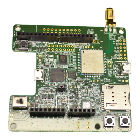
Page 25: Top/Bottom View Of Bc66-Te-B
LPWA Module Series BC66-TE-B User Guide 5.2. Top/Bottom View of BC66-TE-B Figure 12: Top View of the BC66-TE-B Figure 13: Bottom View of the BC66-TE-B BC66-TE-B_User_Guide 24 / 27... -
Page 26: Bc66-Te-B Kit And Accessories
LPWA Module Series BC66-TE-B User Guide BC66-TE-B Kit and Accessories 6.1. BC66-TE-B Kit Figure 14: BC66-TE-B Kit Assembly BC66-TE-B_User_Guide 25 / 27... -
Page 27: Bc66-Te-B Kit Accessories
Figure 15: BC66-TE-B and the Accessories Table 6: Accessories List Item Description Quantity Antenna NB-IoT antenna with SMA connector Cable Micro USB cable A sheet of paper giving instructions for BC66-TE-B connection, Instruction Sheet details of accessories, etc. BC66-TE-B_User_Guide 26 / 27... -
Page 28: Appendix A References
LPWA Module Series BC66-TE-B User Guide Appendix A References Table 7: Related Documents Document Name Remark Quectel_BC66_Hardware_Design BC66 hardware design Table 8: Terms and Abbreviations Abbreviation Description DFOTA Delta Firmware Upgrade Over-the-air Microcontroller Unit NB-IoT Narrow Band Internet of Things...
Need help?
Do you have a question about the BC66-TE-B and is the answer not in the manual?
Questions and answers