
Related Manuals for Quectel UMTS<E EVB


Summary of Contents for Quectel UMTS<E EVB
- Page 1 UMTS<E User Guide UMTS/HSPA/LTE Module Series Rev. UMTS<E_EVB_User_Guide_V2.0 Date: 2017-01-12 www.quectel.com...
- Page 2 QUECTEL OFFERS THE INFORMATION AS A SERVICE TO ITS CUSTOMERS. THE INFORMATION PROVIDED IS BASED UPON CUSTOMERS‟ REQUIREMENTS. QUECTEL MAKES EVERY EFFORT TO ENSURE THE QUALITY OF THE INFORMATION IT MAKES AVAILABLE. QUECTEL DOES NOT MAKE ANY WARRANTY AS TO THE INFORMATION CONTAINED HEREIN, AND DOES NOT ACCEPT ANY LIABILITY FOR ANY INJURY, LOSS OR DAMAGE OF ANY KIND INCURRED BY USE OF OR RELIANCE UPON THE INFORMATION.
-
Page 3: About The Document
UMTS/HSPA/LTE Module Series UMTS<E EVB User Guide About the Document History Revision Date Author Description 2015-03-03 Huik LI Initial 2015-06-10 Radom XIANG Deleted +5V adapter parts in EVB accessories Added applicable modules of the EVB: EC25, EC21, EC20 R2.0, FC20 series and EG95 Added the description of UMTS<E TE-A interface (Chapter 4.2) -
Page 4: Table Of Contents
UMTS/HSPA/LTE Module Series UMTS<E EVB User Guide Contents About the Document ..........................2 Contents ..............................3 Table Index ............................... 5 Figure Index .............................. 6 Introduction ............................7 1.1. Safety Information ......................... 7 General Overview ..........................9 2.1. Applicable Modules ....................... 9 2.2. - Page 5 UMTS/HSPA/LTE Module Series UMTS<E EVB User Guide Appendix A References ........................43 UMTS<E_EVB_User_Guide Confidential / Released 4 / 44...
-
Page 6: Table Index
UMTS/HSPA/LTE Module Series UMTS<E EVB User Guide Table Index TABLE 1: KEY FEATURES ..........................9 TABLE 2: INTERFACES OF UMTS<E EVB ....................11 TABLE 3: ACCESSORIES LIST ........................14 TABLE 4: PIN DEFINITION OF J801 ........................ 21 TABLE 5: PIN DEFINITION OF J601 ........................ 25 TABLE 6: PIN DEFINITION OF J602 ........................ -
Page 7: Figure Index
UMTS/HSPA/LTE Module Series UMTS<E EVB User Guide Figure Index FIGURE 1: UMTS<E EVB INTERFACE OVERVIEW (UNIT: MM) ..............11 FIGURE 2: UMTS<E EVB TOP VIEW ......................13 FIGURE 3: EVB KIT ACCESSORIES ....................... 14 FIGURE 4: UMTS<E EVB KIT ACCESSORIES ASSEMBLY ............... 16 FIGURE 5: POWER SUPPLY FOR UMTS<E EVB .................. -
Page 8: Introduction
Introduction This document describes how to use the evaluation board of UMTS<E modules and Wi-Fi modules. It is an assistant tool for engineers to develop and test Quectel UMTS, LTE and Wi-Fi modules. 1.1. Safety Information The following safety precautions must be observed during all phases of the operation, such as usage, service or repair of any cellular terminal or mobile incorporating UMTS<E and Wi-Fi modules. - Page 9 UMTS/HSPA/LTE Module Series UMTS<E EVB User Guide Your cellular terminal or mobile contains a transmitter and receiver. When it is ON, it receives and transmits radio frequency energy. RF interference can occur if it is used close to TV set, radio, computer or other electric equipment. In locations with potentially explosive atmospheres, obey all posted signs to turn off wireless devices such as your phone or other cellular terminals.
-
Page 10: General Overview
UMTS/HSPA/LTE Module Series UMTS<E EVB User Guide General Overview Quectel supplies UMTS<E EVB for designers to develop applications based on Quectel UMTS<E modules and Wi-Fi modules. This EVB can test basic functionalities of these modules. 2.1. Applicable Modules UMTS<E EVB is applicable to the following module models. - Page 11 UMTS/HSPA/LTE Module Series UMTS<E EVB User Guide Wi-Fi & Ethernet TE-A Support Quectel Wi-Fi modules: FC20 Interface SD Interface Support SD card Support USIM/SIM card insertion detection USIM Card Interface Support USIM/SIM card: 3.0V and 1.8V One digital audio codec board interface...
-
Page 12: Interface Overview
UMTS/HSPA/LTE Module Series UMTS<E EVB User Guide 2.3. Interface Overview J701 S901 SD card J102 100Pin 60Pin 60Pin FC20 TE-A UC20 TE-A J901 J902 UGxx TE-A EC2x TE-A EG95 TE-A J805 J101 J402 J401 100Pin J803 J804 J806 Test Point 60Pin Codec board J501... - Page 13 UMTS/HSPA/LTE Module Series UMTS<E EVB User Guide Power key (push button) S302 Used to turn on/off the UMTS<E module PWRKEY J302 Jumper is used to connect PWRKEY to GND PWRDWN_N S301 Used to turn off the UMTS<E module Reset button (push button). It is used to reset the UMTS<E RESET S303 module...
-
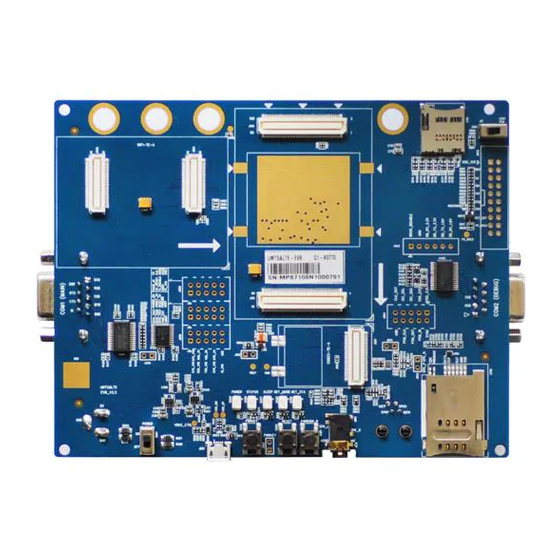
Page 14: Top View Of Evb
UMTS/HSPA/LTE Module Series UMTS<E EVB User Guide J803, J804, J805, Test Points Test pins J806 NOTES The power supply information in above table is for UMTS<E modules. For the detailed information of power supply for Wi-Fi modules, please refer to Chapter 4.1 and Chapter 4.3. This function is only supported by UG35, UG95 and UG96 modules. -
Page 15: Evb Kit Accessories
UMTS/HSPA/LTE Module Series UMTS<E EVB User Guide 2.5. EVB Kit Accessories All accessories of the UMTS<E EVB kit are listed as below. Driver disk USB to UART converter cable Main Wi-Fi Antennas Antenna Bolts and Codec boards nuts RF cables USB cable GNSS Antenna... - Page 16 UMTS/HSPA/LTE Module Series UMTS<E EVB User Guide GNSS Antenna (passive) Wi-Fi Antenna Audio Earphone Disk USB 2.0 to RS232 driver and USB driver disk Codec Boards ALC5616 and TLV320AIC3104 codec boards Others Bolts and nuts for fixing EVB A sheet of paper giving instructions for EVB Instruction Sheet connection, details of EVB accessories, etc.
-
Page 17: Evb Kit Accessories Assembly
UMTS/HSPA/LTE Module Series UMTS<E EVB User Guide EVB Kit Accessories Assembly The following figure shows the EVB Kit accessories assembly. Figure 4: UMTS<E EVB Kit Accessories Assembly UMTS<E_EVB_User_Guide Confidential / Released 16 / 44... -
Page 18: Interface Application
(J201) or USB receptacle (J801) on the EVB. The power adapter connects to a step-down converter which can provide the supply voltage (VBAT) required for operating the EVB and the module. The following two figures show the simplified power supply schematic and the power interface of Quectel UMTS<E EVB. -
Page 19: Umts&Lte Te-A Interface
UMTS/HSPA/LTE Module Series UMTS<E EVB User Guide 5V DC power supply Figure 6: Power Interface Before connecting the power supply, customers have to select a proper DC power adapter to supply power for the UMTS<E EVB, and the power plug design of the adapter is shown as below. Inner contact Outer contact Figure 7: Power Plug Design... -
Page 20: Wi-Fi & Ethernet Te-A Interface
UMTS/HSPA/LTE Module Series UMTS<E EVB User Guide J102 J101 Figure 8: Connection between UMTS<E TE-A and EVB 4.3. Wi-Fi & Ethernet TE-A Interface The Wi-Fi & Ethernet TE-A interface supports FC20 modules, and includes two BTB connectors named J901 and J902, respectively. Wi-Fi & Ethernet TE-A (FC20 TE-A) is connected to the EVB via the two connectors. - Page 21 UMTS/HSPA/LTE Module Series UMTS<E EVB User Guide SGMII_RX_M SGMII_RX_M SGMII_RX_P SGMII_RX_P SGMII_TX_M SGMII_TX_M SGMII_TX_P SGMII_TX_P SGMII_MDIO_DAT SGMII_MDIO_DAT SGMII_MDIO_CLK SGMII_MDIO_CLK SGMII_RST_N SGMII_RST_N SGMII_INT_N SGMII_INT_N SDIO_CMD SDIO_CMD SDIO_CLK SDIO_CLK SDIO_D0 SDIO_D0 SDIO_D1 SDIO_D1 SDIO_D2 SDIO_D2 SDIO_D3 SDIO_D3 VDD_1V8 J901 FC20 TE-A J902 VDD_3V3_FC20 Figure 9: Simplified FC20 TE-A Interface Schematic J902...
-
Page 22: Usb Interface (J801)
UMTS<E EVB User Guide 4.4. USB Interface (J801) Quectel UMTS<E module provides a USB interface which complies with USB 2.0 standard for high-speed (480Mbps), full-speed (12Mbps) and low-speed (1.5Mbps) functions. The interface is used for AT command communication, data transmission, firmware upgrade and GNSS NEMA output. -
Page 23: Audio Interfaces
UMTS/HSPA/LTE Module Series UMTS<E EVB User Guide 4.5. Audio Interfaces Quectel UMTS<E EVB provides one digital audio codec board interface (PCM) J501 and three analog audio interfaces J601, J602 and J603. This chapter gives a detailed introduction on these audio interfaces. -
Page 24: Analog Audio Interfaces (J603/J601/J602)
UMTS/HSPA/LTE Module Series UMTS<E EVB User Guide Codec board Figure 13: Connection between Codec Board and EVB 4.5.2. Analog Audio Interfaces (J603/J601/J602) 4.5.2.1. Loud Speaker Interface (J603) Audio interface J603 is designed for loud speaker and the following figure shows a reference design of loud speaker with an external Class-D audio amplifier. -
Page 25: Earphone Interface (J601)
UMTS/HSPA/LTE Module Series UMTS<E EVB User Guide 4.5.2.2. Earphone Interface (J601) Audio interface J601 is designed for earphones. The names of corresponding pins on EVB are shown in Figure 16. A reference circuit designs for earphone interfaces J601 is shown as following figure. Close to Socket Differential layout AGND... -
Page 26: Handset Interface (J602)
UMTS/HSPA/LTE Module Series UMTS<E EVB User Guide Table 5: Pin Definition of J601 Pin No. Pin Name Description Microphone input AGND Dedicated GND for audio SPK_R Right channel of stereo audio output SPK_L Left channel of stereo audio output 5, 6 Not connected The following figure shows the sketch design of audio plug which suits for the audio jack on UMTS<E EVB. - Page 27 UMTS/HSPA/LTE Module Series UMTS<E EVB User Guide J501 U101 Codec 10pF 33pF 10pF 33pF 10pF 33pF ALC5616 TLV3104 J602 IN2P IN2N LOUDL/P LOUDR/N 10pF 33pF 10pF 33pF 10pF 33pF BTB CON Figure 18: Reference Circuit Design for Handset Interface J602 Figure 19: Pin Assignments of J602 UMTS<E_EVB_User_Guide Confidential / Released...
-
Page 28: Usim Card Interface (J702)
UMTS/HSPA/LTE Module Series UMTS<E EVB User Guide Table 6: Pin Definition of J602 Pin No. Pin Name Function MICN Negative microphone input SPKN Negative loud speaker output SPKP Positive loud speaker output MICP Positive microphone input 4.6. USIM Card Interface (J702) The UMTS<E EVB has a 6-pin push-push type USIM card (3V or 1.8V) connector J702. - Page 29 UMTS/HSPA/LTE Module Series UMTS<E EVB User Guide The following figure shows the pin assignments of J702. Figure 21: Pin Assignments of J702 Table 7: Pin Definition of J702 Pin No. Signal Name Function USIM card power supply, provided by USIM_VDD UMTS<E EVB USIM_RST USIM card reset...
-
Page 30: Sd Card Interface (J701)
UMTS/HSPA/LTE Module Series UMTS<E EVB User Guide 4.7. SD Card Interface (J701) The UMTS<E EVB provides an SD card interface that supports maximally 32GB micro SD card. With the SD card interface, customers can easily enhance the memory capacity of modules. The following figure shows the simplified interface schematic for J701. -
Page 31: Uart Interfaces (J401/J402)
UMTS/HSPA/LTE Module Series UMTS<E EVB User Guide 4.8. UART Interfaces (J401/J402) The UMTS<E EVB offers two UART interfaces: COM1 (Main UART port J401 and J402) and COM2 (Debug UART port). COM1 of UMTS<E EVB is intended for the communication between the module and the host application. - Page 32 UMTS/HSPA/LTE Module Series UMTS<E EVB User Guide Table 8: Pin Definition of J401 Pin No. Signal Name Description RS232_DCD Data carrier detection RS232_RXD Receive data RS232_TXD Transmit data RS232_DTR Data terminal ready RS232_GND Not connected RS232_RTS Request to send RS232_CTS Clear to send RS232_RI Ring indicator...
-
Page 33: Switches And Buttons
UMTS/HSPA/LTE Module Series UMTS<E EVB User Guide 4.9. Switches and Buttons The UMTS<E EVB includes two switches (S201 and S901) and three buttons (S301, S302 and S303), as shown in the following figures. S901 Figure 27: S901 Switch S302 S303 S301 S201 Figure 28: S201 Switch and S301/S302/S303 Buttons... -
Page 34: Status Indication Leds
UMTS/HSPA/LTE Module Series UMTS<E EVB User Guide on EVB to UMTS<E module, for testing the module's main UART functions, and the codec„s PCM function. S302 Used to turn on/off the UMTS<E module S303 Used to reset the UMTS<E module S301 Used to turn off the UMTS<E module NOTE This function is only supported by UG35, UG95 and UG96 modules. -
Page 35: Test Points
UMTS/HSPA/LTE Module Series UMTS<E EVB User Guide Bright: the module is powered on Extinct: the module is powered down Indicate the sleep status of UMTS<E module D207 Bright: the module is in sleep mode Extinct: the module is not in sleep mode Indicate the network status of UMTS<E module, for detailed information please refer D208, D206 to document [2]. - Page 36 UMTS/HSPA/LTE Module Series UMTS<E EVB User Guide J804 Figure 31: Test Point J804 Table 12: Pin Definition of J803, J804, J805 and J806 J803 Pin No. Pin Name Description 1,3,5 DTR_TEST Data terminal ready test pins POWER_EN VBAT enable pin PWRKEY_3.0V PWRKEY_3.0V test pin RESET_3.0V...
- Page 37 UMTS/HSPA/LTE Module Series UMTS<E EVB User Guide I2C_SDA Connected directly to I2C_SDA of UMTS<E module PCM_OUT Connected directly to PCM_OUT of UMTS<E module I2C_SCL Connected directly to I2C_SCL of UMTS<E module PCM_CLK Connected directly to PCM_CLK of UMTS<E module CLK_OUT RESERVED Ground J805 Pin No.
- Page 38 UMTS/HSPA/LTE Module Series UMTS<E EVB User Guide DTR_3.0V Connected directly to voltage translator RI_1.8V Connected directly to RI of UMTS<E module Ground UMTS<E_EVB_User_Guide Confidential / Released 37 / 44...
-
Page 39: Operation Procedures Illustration
UMTS/HSPA/LTE Module Series UMTS<E EVB User Guide Operation Procedures Illustration This chapter introduces how to use the UMTS<E EVB for testing and evaluation of Quectel UMTS<E modules and Wi-Fi modules. 5.1. Power on UMTS<E and Wi-Fi Modules Power on UMTS<E module 1. -
Page 40: Communication Via Usb Or Uart Interface
The USB port numbers can be viewed through the PC Device Manager, shown as following figure. Figure 32: USB Ports Install and then use the QCOM tool provided by Quectel to realize the communication between the UMTS<E module and the PC. The following figure shows the QCOM window configuration: select correct “COM port”... -
Page 41: Communication Via Uart Interface
Figure 34: USB Serial Port Install and then use the QCOM tool provided by Quectel to realize the communication between the UMTS<E module and the PC. The following figure shows the QCOM window configuration: select correct “COM port” (USB Serial Port) and set correct “Baudrate” (such as 115,200bps). For more details about QCOM tool usage and configuration, please refer to document [6]. -
Page 42: Firmware Upgrade
UMTS<E EVB User Guide 5.3. Firmware Upgrade Quectel UMTS<E module upgrades firmware via USB port by default, please follow the procedures below to upgrade firmware. Install and open the firmware upgrade tool QFlash on PC and then power on the UMTS<E module according to the procedures mentioned in Chapter 5.1. -
Page 43: Power Off Umts&Lte And Wi-Fi Modules
UMTS/HSPA/LTE Module Series UMTS<E EVB User Guide 5.5. Power off UMTS<E and Wi-Fi Modules Power off UMTS<E module There are two ways to power off UMTS<E module. One way is to execute AT command AT+QPOWD. This is the best and the safest way. The module will log off from the network and save data before shutdown, but it will be powered on again after shutdown. - Page 44 Hardware design for UC20, UG95, Quectel_xx_Hardware_Design UG96, EC25, EC21, EC20 and EC20 R2.0 Quectel_FC20_Series_Hardware_Design FC20 series hardware design AT commands manual for Quectel Quectel_WCDMA_UGxx_AT_Commands_Manual WCDMA UGxx modules AT commands manual for UC20, EC25, Quectel_xx_AT_Commands_Manual EC21, EC20 and EC20 R2.0 Quectel_QCOM_User_Guide...
- Page 45 UMTS/HSPA/LTE Module Series UMTS<E EVB User Guide Ground GNSS Global Navigation Satellite System Input/Output Light Emitting Diode Long Term Evolution Microphone Not Connected Private Computer Printed Circuit Board Pulse Code Modulation Power Output Radio Frequency Secure Digital Subscriber Identity Module UART Universal Asynchronous Receiver &...
Need help?
Do you have a question about the UMTS<E EVB and is the answer not in the manual?
Questions and answers