
Related Manuals for Quectel BC950K-GL TE-B


Summary of Contents for Quectel BC950K-GL TE-B
- Page 1 BC950K-GL TE-B User Guide NB-IoT Module Series Version: 1.0 Date: 2023-09-27 Status: Released...
-
Page 2: Legal Notices
NB-IoT Module Series At Quectel, our aim is to provide timely and comprehensive services to our customers. If you require any assistance, please contact our headquarters: Quectel Wireless Solutions Co., Ltd. Building 5, Shanghai Business Park Phase III (Area B), No.1016 Tianlin Road, Minhang District, Shanghai... -
Page 3: Third-Party Rights
Except as otherwise set forth herein, nothing in this document shall be construed as conferring any rights to use any trademark, trade name or name, abbreviation, or counterfeit product thereof owned by Quectel or any third party in advertising, publicity, or other aspects. -
Page 4: Safety Information
Manufacturers of the terminal should notify users and operating personnel of the following safety information by incorporating these guidelines into all manuals of the product. Otherwise, Quectel assumes no liability for customers’ failure to comply with these precautions. -
Page 5: About The Document
NB-IoT Module Series About the Document Revision History Version Date Author Description 2023-08-14 Weida LIU Creation of the document 2023-09-27 Weida LIU First official release BC950K-GL_TE-B_User_Guide 4 / 28... -
Page 6: Table Of Contents
NB-IoT Module Series Contents Safety Information ............................3 About the Document ..........................4 Contents ..............................5 Table Index ..............................6 Figure Index ..............................7 Introduction ............................8 Product Overview ..........................9 2.1. Top and Bottom Views ....................... 9 2.2. Component Placement ......................11 2.3. - Page 7 NB-IoT Module Series Table Index Table 1: Components Information .......................11 Table 2: Key Features of TE-B ........................14 Table 3: Accessories List ..........................17 Table 4: Pin Connection Between TE-B and STM32-L476RG MCU ............23 Table 5: Related Documents ........................27 Table 6: Terms and Abbreviations ......................
- Page 8 NB-IoT Module Series Figure Index Figure 1: Top View ............................9 Figure 2: Bottom View ..........................10 Figure 3: Component Placement ........................11 Figure 4: Arduino Interface Definition ......................13 Figure 5: Functional Diagram of TE-B ....................... 15 Figure 6: TE-B Kit Accessories Assembly ....................16 Figure 7: TE-B Kit Accessories ........................
-
Page 9: Introduction
Introduction To help you to develop applications with Quectel BC950K-GL conveniently, Quectel supplies corresponding development board (BC950K-GL TE-B) to test the module. This document can help you quickly understand BC950K-GL TE-B interface specifications, RF characteristics, electrical and mechanical details and know how to use it. -
Page 10: Product Overview
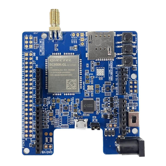
NB-IoT Module Series Product Overview BC950K-GL TE-B is an NB-IoT development board which supports Arduino interface and it can be used either alone or in conjunction with STM32 Nucleo-64 development board to develop and debug applications which communicate with infrastructures of mobile network operators through NB-IoT radio protocols in 3GPP Rel-13 and 3GPP Rel-14. - Page 11 NB-IoT Module Series Figure 2: Bottom View BC950K-GL_TE-B_User_Guide 10 / 28...
-
Page 12: Component Placement
NB-IoT Module Series 2.2. Component Placement J0101 J0301 J0308 D0303 U0101 J0306 U0306 U0301 J0305 J0206 J0401 J0205 U0203 U0201 U0202 U0305 J0304 S0102 S0103 S0101 J0303 J0107 D0204 J0201 S0301 Figure 3: Component Placement Table 1: Components Information Components RefDes Description BC950K-GL... - Page 13 NB-IoT Module Series J0202 External power supply interface J0201 Power adapter power supply interface J0303 Arduino power supply interface USB-to-UART Interface J0305 Support 2 UART interfaces USIM Interface J0401 Micro-SIM card connector J0301, J0303, Arduino Interfaces Standard Arduino interfaces J0304, J0308 ANT_RF J0306 RF SMA connector...
-
Page 14: Arduino Interface Definition
NB-IoT Module Series 2.3. Arduino Interface Definition UART_MCU_TX UART_MCU_RX WAKEUP_N RESET_N 3.3V 3.3V Figure 4: Arduino Interface Definition BC950K-GL_TE-B_User_Guide 13 / 28... -
Page 15: Key Features
NB-IoT Module Series 2.4. Key Features Table 2: Key Features of TE-B Parameters Details USB interface: ⚫ Supply voltage range: 4.75–5.25 V ⚫ Typical supply voltage: 5.0 V Arduino interface: ⚫ Supply voltage range: 4.75–5.25 V Power Supply ⚫ Typical supply voltage: 5.0 V Power adapter interface: ⚫... -
Page 16: Functional Diagram
NB-IoT Module Series Size (23.6 ± 0.15) mm × (19.9 ± 0.15) mm × (2.2 ± 0.2) mm ⚫ Main UART Firmware Upgrade ⚫ DFOTA 50 Ω characteristic impedance Antenna Interface 2.5. Functional Diagram DC JACK J0201 DC-DC U0203 ANT_RF J0306 U0201 U0202 J0301... -
Page 17: Kit Accessories & Assembly
NB-IoT Module Series Kit Accessories & Assembly 3.1. Accessories Assembly Figure 6: TE-B Kit Accessories Assembly BC950K-GL_TE-B_User_Guide 16 / 28... -
Page 18: Accessories List
NB-IoT Module Series 3.2. Accessories List Figure 7: TE-B Kit Accessories Table 3: Accessories List Item Description Quantity (pcs) Antenna NB-IoT antenna with SMA connector Cable Micro USB cable A sheet of paper giving instructions for TE-B Instruction Sheet connection, details of accessories, etc. BC950K-GL_TE-B_User_Guide 17 / 28... -
Page 19: Operation Procedures
NB-IoT Module Series Operation Procedures BC950K-GL TE-B can be used alone to upgrade firmware and debug applications based on BC950K-GL. Also, it can be used in conjunction with an STM32 Nucleo-64 development board via Arduino interface to develop NB-IoT applications based on STM32. The following describes the operation procedures of TE-B in different operation modes. -
Page 20: Operation Procedures Of Using Te-B Alone
NB-IoT Module Series 4.1.2. Operation Procedures of Using TE-B Alone Install USB-to-UART driver which can be downloaded from the following link: https://www.wch.cn/downloads/USBMSER_exe.html; Insert a Micro-SIM card into J0401, and please note that an NB-IoT USIM card should be selected. Connect the rod antenna with SMA connector on J0306 (RF antenna connector). Switch S0301 (UART switch) to “UART-to-USB”... -
Page 21: Operation Procedure With Multi Boards
NB-IoT Module Series 4.2. Operation Procedure with Multi Boards 4.2.1. Interface Diagram of Using Multi Boards J0101 J0301 J0308 D0303 J0306 J0305 J0206 J0401 J0205 J0304 S0102 S0103 S0101 J0303 J0107 D0204 J0201 S0301 Figure 10: Interface Diagram of Using Multi Boards BC950K-GL_TE-B_User_Guide 20 / 28... - Page 22 NB-IoT Module Series Figure 11: STM32 Nucleo-64 Board Interface Diagram (Top View) SB13 SB14 SB62 SB63 Figure 12: STM32 Nucleo-64 Board Modification Diagram (Bottom View) BC950K-GL_TE-B_User_Guide 21 / 28...
-
Page 23: Operation Procedures Of Using Multi Boards
NB-IoT Module Series 4.2.2. Operation Procedures of Using Multi Boards 1. Install a driver for STM32 Nucleo-64 board, which can be downloaded from the following link: http://www.st.com/content/st_com/en/products/evaluation-tools/product-evaluation-tools/mcu-eval- tools/stm32-mcu-eval-tools/stm32-mcu-nucleo/nucleo-l476rg.html; 2. Install a USB-to-UART driver which can be downloaded from the following link: https://www.wch.cn/downloads/USBMSER_exe.html ;... - Page 24 NB-IoT Module Series Table 4: Pin Connection Between TE-B and STM32-L476RG MCU MCU (Morpho) Arduino TE-B Description CN9-2 UART_MCU_TX Connect to main UART RX CN9-1 UART_MCU_RX Connect to main UART TX External interrupt for CN5-4 WAKEUP_N Deep Sleep/Light Sleep CN5-6 RESET_EN Active high CN8-1...
-
Page 25: Power Consumption Test Guide
4.3. Power Consumption Test Guide 4.3.1. Test Tools The following are the equipment and tools needed for the power consumption test: ⚫ BC950K-GL TE-B ⚫ DC power analyzer ⚫ Wire, soldering iron, tin wire, and wire stripping pliers, etc. to weld the power supply cord on TE-B. -
Page 26: Power Consumption Test Steps
NB-IoT Module Series J0206 J0202 Figure 15: Schematic Diagram of TE-B Before Modification 4.3.3. Power Consumption Test Steps Please refer to the following steps to test the current consumption of the module on the modified TE-B: Insert the USIM card; Insert the USB cable into TE-B;... - Page 27 NB-IoT Module Series Turn on the output voltage set by N6705C, and the module will automatically turn on after power on; Conduct current consumption tests in different modes. RF antenna USIM J0206 Power supply 3.6 V J0202 Left: VBAT Right: GND Plug in the USB cable Figure 16: TE-B Wiring Diagram BC950K-GL_TE-B_User_Guide...
-
Page 28: Appendix References
NB-IoT Module Series Appendix References Table 5: Related Documents Document Name [1] Quectel_BC950K-GL_Hardware_Design Table 6: Terms and Abbreviations Abbreviation Description 3GPP 3rd Generation Partnership Project Bits Per Second Communication Direct Current DFOTA Delta Firmware Upgrade Over-the-Air Ground Low-dropout Regulator Microcontroller Unit NB-IoT Narrowband Internet of Things Personal Computer... - Page 29 NB-IoT Module Series Universal Serial Bus USIM Universal Subscriber Identification Module VBAT Voltage at Battery BC950K-GL_TE-B_User_Guide 28 / 28...
Need help?
Do you have a question about the BC950K-GL TE-B and is the answer not in the manual?
Questions and answers