
Related Manuals for Quectel BC95-TE-B


Summary of Contents for Quectel BC95-TE-B
- Page 1 BC95-TE-B User Guide NB-IoT Module Series Rev. BC95-TE-B_User_Guide_V1.0 Date: 2017-08-07 www.quectel.com...
- Page 2 QUECTEL OFFERS THE INFORMATION AS A SERVICE TO ITS CUSTOMERS. THE INFORMATION PROVIDED IS BASED UPON CUSTOMERS’ REQUIREMENTS. QUECTEL MAKES EVERY EFFORT TO ENSURE THE QUALITY OF THE INFORMATION IT MAKES AVAILABLE. QUECTEL DOES NOT MAKE ANY WARRANTY AS TO THE INFORMATION CONTAINED HEREIN, AND DOES NOT ACCEPT ANY LIABILITY FOR ANY INJURY, LOSS OR DAMAGE OF ANY KIND INCURRED BY USE OF OR RELIANCE UPON THE INFORMATION.
-
Page 3: About The Document
NB-IoT Module Series BC95-TE-B User Guide About the Document History Revision Date Author Description Ewent LU/ 2017-08-07 Initial Vae LIU BC95-TE-B_User_Guide Confidential / Released 2 / 22... -
Page 4: Table Of Contents
Arduino Interface Definition ..................... 11 Operation Procedures ........................12 3.1. Operation Procedures with Single Board ................12 3.1.1. Interface Diagram of Using BC95-TE-B Alone .............. 12 3.1.2. Operation Procedures of Using BC95-TE-B Alone ............13 3.2. Operation Procedures with Multi Boards ................. 13 3.2.1. - Page 5 Table Index TABLE 1: KEY FEATURES OF BC95-TE-B ......................8 TABLE 2: INTERFACES OF BC95-TE-B ......................10 TABLE 3: PIN CONNECTION BETWEEN BC95-TE-B AND STM32-L476RG MCU ........16 TABLE 4: ABSOLUTE MAXIMUM RATINGS ....................18 TABLE 5: OPERATING TEMPERATURE ......................18 TABLE 6: RELATED DOCUMENTS ........................
- Page 6 FIGURE 8: STM32-NUCLEO MODIFICATION DIAGRAM (BOTTOM VIEW) ..........15 FIGURE 9: ST-LINK INTERFACE DISPLAYED ON PC ..................16 FIGURE 10: PIN CONNECTION BETWEEN BC95-TE-B AND STM32-L476RG MCU ........17 FIGURE 11: DIMENSIONS OF BC95-TE-B (TOP VIEW) ................. 20 FIGURE 12: TOP VIEW OF THE BC95-TE-B ....................21 FIGURE 13: BOTTOM VIEW OF THE BC95-TE-B ...................
-
Page 7: Introduction
If not so, Quectel assumes no liability for the customers’ failure to comply with these precautions. - Page 8 NB-IoT Module Series BC95-TE-B User Guide Your cellular terminal or mobile contains a transmitter and receiver. When it is ON, it receives and transmits radio frequency energy. RF interference can occur if it is used close to TV set, radio, computer or other electric equipment.
-
Page 9: Product Concept
BC95-TE-B is a NB-IoT evaluation board which supports Arduino interface. Designed in 74.0mm × 70.0mm × 1.6mm form factor, BC95-TE-B can be used either alone or in conjunction with STM32 Nucleo-64 development board, in order to develop and debug applications for communication with mobile network operators’... -
Page 10: Functional Diagram
When the temperature returns to the normal operating temperature levels, the module will meet 3GPP specifications again. DFOTA function is only supported on B657 version or later. 2.2. Functional Diagram The following figure shows a block diagram of BC95-TE-B. U102 U103 J208 BC95... -
Page 11: Interface Distribution Diagram
NB-IoT Module Series BC95-TE-B User Guide 2.3. Interface Distribution Diagram The following figure shows an interface distribution diagram of BC95-TE-B. J101 J205 J207 D204 J103 J208 J102 J104 J209 J201 J202 J204 J203 S201 Figure 2: Interface Distribution Diagram of BC95-TE-B The table below shows the description of BC95-TE-B interfaces. -
Page 12: Arduino Interface Definition
Used to test the basic functionalities of BC95 Test Points J101, J102, J103, J104 module 2.4. Arduino Interface Definition The following figure shows the Arduino interface definition of BC95-TE-B. Figure 3: Arduino Interface Definition BC95-TE-B_User_Guide Confidential / Released 11 / 22... -
Page 13: Operation Procedures
NB-IoT applications based on BC95-TE-B. Meanwhile, it can also be used in conjunction with an STM32 Nucleo-64 development board via Arduino interface to develop NB-IoT applications based on STM32. The following part describes the two ways of using BC95-TE-B in detail. 3.1. Operation Procedures with Single Board This section elaborates the operation procedures of using the BC95-TE-B alone. -
Page 14: Operation Procedures Of Using Bc95-Te-B Alone
Switch “UART_SWITCH” to “BC95 TO USB” state; Connect the J209 with PC via Micro USB cable. After turning on BC95-TE-B, UART port information will be shown on device manager of PC. CH A is the main port and can be used for AT command communication and firmware upgrading. -
Page 15: Interface Diagram Of Using Multi Boards
NB-IoT Module Series BC95-TE-B User Guide 3.2.1. Interface Diagram of Using Multi Boards J203 J209 J205 J202 J207 J204 J207 J208 Figure 6: Interface Diagram of Using Multi Boards Figure 7: STM32-Nucleo Interface Diagram (Top View) BC95-TE-B_User_Guide Confidential / Released... -
Page 16: Operation Procedures Of Using Multi Boards
Switch “UART_SWITCH” to “BC95 TO MCU” state; Connect Arduino interface to STM32-Nucleo board, and connect J202, J204, J205 and J207 of BC95-TE-B to CN6, CN8, CN5 and CN9 respectively. Connect CN1 of STM32-Nucleo board with PC via Mini USB cable. After powering on BC95 module, device information will be shown on the device manager of PC. -
Page 17: Description Of Pin Connection
NB-IoT Module Series BC95-TE-B User Guide Figure 9: ST-LINK Interface Displayed on PC 3.2.3. Description of Pin Connection The table below shows the pin connection between BC95-TE-B and STM32-L476RG MCU. Table 3: Pin Connection between BC95-TE-B and STM32-L476RG MCU MCU (Morpho) Arduino... - Page 18 NB-IoT Module Series BC95-TE-B User Guide The following figure shows the pin connection between BC95-TE-B and STM32-L476RG MCU. Figure 10: Pin Connection between BC95-TE-B and STM32-L476RG MCU BC95-TE-B_User_Guide Confidential / Released 17 / 22...
-
Page 19: Electrical And Reliability
NB-IoT Module Series BC95-TE-B User Guide Electrical and Reliability 4.1. Absolute Maximum Ratings Absolute maximum ratings for power supply and voltage on digital and analog pins of the BC95 module are listed in the following table. Table 4: Absolute Maximum Ratings Parameter Min. - Page 20 NB-IoT Module Series BC95-TE-B User Guide NOTES Within operation temperature range, the module is 3GPP compliant. Within extended temperature range, the module remains the ability to establish and maintain an SMS, data transmission, etc. There is no unrecoverable malfunction. There are also no effects on radio spectrum and no harm to radio network.
-
Page 21: Mechanical Dimensions
NB-IoT Module Series BC95-TE-B User Guide Mechanical Dimensions This chapter describes the mechanical dimensions of BC95-TE-B. All dimensions are measured in mm. The tolerances for dimensions are ± 0.15mm. 5.1. Mechanical Dimensions of BC95-TE-B Figure 11: Dimensions of BC95-TE-B (Top View) -
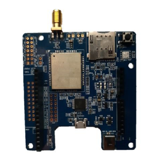
Page 22: Design Effect Drawings Of Bc95-Te-B
Figure 12: Top View of the BC95-TE-B Figure 13: Bottom View of the BC95-TE-B NOTE These are design effect drawings of BC95-TE-B. For more accurate pictures, please refer to the BC95-TE-B that you get from Quectel. BC95-TE-B_User_Guide Confidential / Released... -
Page 23: Appendix A References
NB-IoT Module Series BC95-TE-B User Guide Appendix A References Table 6: Related Documents Document Name Remark Quectel_BC95_Hardware_Design BC95 hardware design specifications Table 7: Terms and Abbreviations Abbreviation Description Integrated Circuit Microcontroller Unit NB-IoT Narrow Band Internet of Things UART Universal Asynchronous Receiver & Transmitter...
Need help?
Do you have a question about the BC95-TE-B and is the answer not in the manual?
Questions and answers