
Related Manuals for Quectel BC92-TE-B


Summary of Contents for Quectel BC92-TE-B
- Page 1 BC92-TE-B User Guide LPWA/GSM/GPRS Module Series Rev. BC92-TE-B_User_Guide_V1.0 Date: 2019-06-24 Status: Preliminary www.quectel.com...
- Page 2 QUECTEL OFFERS THE INFORMATION AS A SERVICE TO ITS CUSTOMERS. THE INFORMATION PROVIDED IS BASED UPON CUSTOMERS’ REQUIREMENTS. QUECTEL MAKES EVERY EFFORT TO ENSURE THE QUALITY OF THE INFORMATION IT MAKES AVAILABLE. QUECTEL DOES NOT MAKE ANY WARRANTY AS TO THE INFORMATION CONTAINED HEREIN, AND DOES NOT ACCEPT ANY LIABILITY FOR ANY INJURY, LOSS OR DAMAGE OF ANY KIND INCURRED BY USE OF OR RELIANCE UPON THE INFORMATION.
-
Page 3: About The Document
LPWA/GSM/GPRS Module Series BC92-TE-B User Guide About the Document History Revision Date Author Description Glenn GE/ 2019-06-24 Initial Erwin TANG BC92-TE-B_User_Guide 2 / 28... -
Page 4: Table Of Contents
Operation and Storage Temperature ..................21 Mechanical Dimensions ........................23 5.1. Mechanical Dimensions of BC92-TE-B ................... 23 5.2. Top and Bottom View of BC92-TE-B ..................24 BC92-TE-B Kit and Accessories ....................... 26 6.1. BC92-TE-B Kit ......................... 26 6.2. BC92-TE-B Accessories ......................27 Appendix A References ........................ - Page 5 Table Index TABLE 1: KEY FEATURES OF BC92-TE-B ......................8 TABLE 2: INTERFACES OF BC92-TE-B ......................11 TABLE 3: PIN CONNECTION BETWEEN BC92-TE-B AND STM32-L476RG MCU ........19 TABLE 4: ABSOLUTE MAXIMUM RATINGS ....................21 TABLE 5: OPERATING TEMPERATURE ......................21 TABLE 6: ACCESSORY LIST ..........................
- Page 6 FIGURE 8: STM32-NUCLEO MODIFICATION DIAGRAM (BOTTOM VIEW) ..........18 FIGURE 9: ST-LINK INTERFACE DISPLAYED ON PC ..................19 FIGURE 10: PIN CONNECTION BETWEEN BC92-TE-B AND STM32-L476RG MCU ........20 FIGURE 11: DIMENSIONS OF BC92-TE-B (TOP VIEW) ................. 23 FIGURE 12: TOP VIEW OF THE BC92-TE-B ....................24 FIGURE 13: BOTTOM VIEW OF THE BC92-TE-B ...................
-
Page 7: Introduction
If not so, Quectel assumes no liability for the customers’ failure to comply with these precautions. - Page 8 LPWA/GSM/GPRS Module Series BC92-TE-B User Guide The cellular terminal or mobile contains a transmitter and receiver. When it is ON, it receives and transmits radio frequency signals. RF interference can occur if it is used close to TV set, radio, computer or other electric equipment.
-
Page 9: Product Concept
BC92-TE-B is a LPWA/GSM/GPRS evaluation board which supports Arduino interface. Designed in 100.0mm × 95.0mm × 1.6mm form factor, BC92-TE-B can be used either alone or in conjunction with STM32 Nucleo-64 development board, in order to develop and debug applications for communication with mobile network operators’... - Page 10 LPWA/GSM/GPRS Module Series BC92-TE-B User Guide Support two UART ports Main port (USB Serial Converter A): Used for AT command communication and data transmission, baud rates 2400bps, 4800bps, 9600bps (default), 14400bps, 19200bps, 28800bps, 33600bps, 38400bps and 57600bps are supported Main port can also be used for firmware upgrading*, and the baud ...
-
Page 11: Functional Diagram
LPWA/GSM/GPRS Module Series BC92-TE-B User Guide 2.2. Functional Diagram The following figure shows a block diagram of BC92-TE-B. EARPHONE J305 DC JACK AUDIO J308 LDO U201 Switch LDO U203 S201 LDO U202 J309 BC92 J301/J502/ U101 J503 J310 Switch USB-UART... -
Page 12: Interface Distribution Diagram
LPWA/GSM/GPRS Module Series BC92-TE-B User Guide 2.3. Interface Distribution Diagram The following figure shows an interface distribution diagram of BC92-TE-B. Figure 2: Interface Distribution Diagram of BC92-TE-B The table below shows the description of BC92-TE-B interfaces. Table 2: Interfaces of BC92-TE-B... - Page 13 LPWA/GSM/GPRS Module Series BC92-TE-B User Guide J309 Power supply for Arduino interface USB Interface J306 Support two UART ports USIM Card Interface J401, J402 Micro USIM card connector Arduino Interface J307, J309, J310, J311 Standard Arduino interface RF Antenna Interface...
-
Page 14: Arduino Interface Definition
LPWA/GSM/GPRS Module Series BC92-TE-B User Guide 2.4. Arduino Interface Definition The following figure shows the Arduino interface definition of BC92-TE-B. Figure 3: Arduino Interface Definition BC92-TE-B_User_Guide 13 / 28... -
Page 15: Operation Procedures
BC92-TE-B User Guide Operation Procedures This chapter mainly illustrates the operation procedures of BC92-TE-B. BC92-TE-B can be used alone to upgrade and debug NB-IoT/GSM/GPRS applications. Meanwhile, it can also be used in conjunction with an STM32 Nucleo-64 development board via Arduino interface to develop NB-IoT applications based on STM32. -
Page 16: Interface Diagram
Connect the J306 (USB Interface) with PC via Micro USB cable, switch S201 to “ON”. After turning on BC92-TE-B, UART port information will be shown in the device manager on PC, as manifested in the following figure. “USB Serial Port (COM19)” (corresponding to “USB Serial Converter A”) is... - Page 17 LPWA/GSM/GPRS Module Series BC92-TE-B User Guide connected to the main port of BC92 and can be used for AT command communication and firmware upgrade*. “USB Serial Port (COM20)” (corresponding to “USB Serial Converter B”) is connected to the debug port of BC92 and can be used for debugging, debug log output and firmware upgrade. For details of port configuration, please refer to Quectel_ BC92_Hardware_Design.
-
Page 18: Operation Procedure With Multi Boards
LPWA/GSM/GPRS Module Series BC92-TE-B User Guide 3.2. Operation Procedure with Multi Boards This section elaborates the operation procedure when using BC92-TE-B in conjunction with an STM32 Nucleo-64 development board. 3.2.1. Interface and Modification Diagrams J204 Figure 6: Interface Diagram When Using Multi Boards... - Page 19 LPWA/GSM/GPRS Module Series BC92-TE-B User Guide Figure 7: STM32-Nucleo Modification Diagram (Top View) SB13 SB14 SB62 SB63 Figure 8: STM32-Nucleo Modification Diagram (Bottom View) BC92-TE-B_User_Guide 18 / 28...
-
Page 20: Operation Procedure When Using Multi Boards
BC92 module, device information will be shown in the device manager on PC. Figure 9: ST-LINK Interface Displayed on PC 3.2.3. Description of Pin Connection The table below shows the pin connection between BC92-TE-B and STM32-L476RG MCU. Table 3: Pin Connection between BC92-TE-B and STM32-L476RG MCU MCU (Morpho) - Page 21 CN5-5 PWRKEY_N Active high CN5-6 RESET_N Active high CN8-1 CN6-5 5.0V power supply CN5-7, CN6-6, CN6-7 GND Ground The following figure shows the pin connection between BC92-TE-B and STM32-L476RG MCU. RESET_EN +3.3V PWRKEY_EN PSM_EINT_EN +3.3V UART_MCU_TX UART_MCU_RX Arduino BC92-TE-B Morpho...
-
Page 22: Electrical Performance And Reliability
LPWA/GSM/GPRS Module Series BC92-TE-B User Guide Electrical Performance and Reliability 4.1. Absolute Maximum Ratings Absolute maximum ratings for power supply and voltage on digital and analog pins of BC92 module are listed in the following table. Table 4: Absolute Maximum Ratings Parameter Min. - Page 23 LPWA/GSM/GPRS Module Series BC92-TE-B User Guide NOTES Within operation temperature range, the module is 3GPP compliant. Within extended temperature range, the module remains the ability to establish and maintain functions such as SMS and data transmission, without any unrecoverable malfunction. Radio spectrum and radio network will not be influenced.
-
Page 24: Mechanical Dimensions
LPWA/GSM/GPRS Module Series BC92-TE-B User Guide Mechanical Dimensions This chapter describes the mechanical dimensions of BC92-TE-B. All dimensions are measured in mm. The tolerances for dimensions are ±0.15mm. 5.1. Mechanical Dimensions of BC92-TE-B Figure 11: Dimensions of BC92-TE-B (Top View) -
Page 25: Top And Bottom View Of Bc92-Te-B
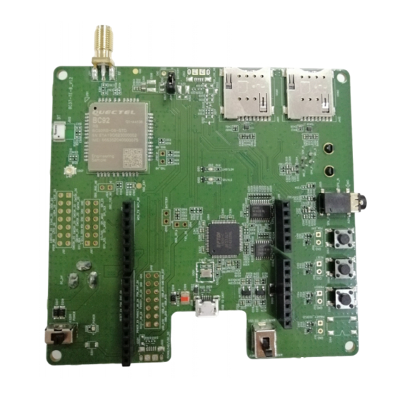
LPWA/GSM/GPRS Module Series BC92-TE-B User Guide 5.2. Top and Bottom View of BC92-TE-B Figure 12: Top View of the BC92-TE-B BC92-TE-B_User_Guide 24 / 28... - Page 26 LPWA/GSM/GPRS Module Series BC92-TE-B User Guide Figure 13: Bottom View of the BC92-TE-B BC92-TE-B_User_Guide 25 / 28...
-
Page 27: Bc92-Te-B Kit And Accessories
LPWA/GSM/GPRS Module Series BC92-TE-B User Guide BC92-TE-B Kit and Accessories 6.1. BC92-TE-B Kit Figure 14: BC92-TE-B Kit BC92-TE-B_User_Guide 26 / 28... -
Page 28: Bc92-Te-B Accessories
BC92-TE-B User Guide 6.2. BC92-TE-B Accessories Figure 15: BC92-TE-B and Accessories Table 6: Accessory List Accessories Description. Quantity RF Antenna Rod antenna with SMA connector Cable Micro USB cable Instruction Instruction about BC92-TE-B connection and relevant accessories BC92-TE-B_User_Guide 27 / 28... -
Page 29: Appendix A References
LPWA/GSM/GPRS Module Series BC92-TE-B User Guide Appendix A References Table 7: Related Documents Document Name Remark Quectel_BC92_Hardware_Design BC92 hardware design specifications Table 8: Terms and Abbreviations Abbreviation Description GPRS General Packet Radio Service LPWA Low Power Wide Area DFOTA Delta Firmware Upgrade Over-the-air...
Need help?
Do you have a question about the BC92-TE-B and is the answer not in the manual?
Questions and answers