
Related Manuals for Harvest TEC 442P


Summary of Contents for Harvest TEC 442P
- Page 1 OWNER’S MANUAL Model 442P / 442U / 442UP 25 and 55 Gallon Preservative Applicators Forage Harvester 442P-442U-442UP-23- OwnerManual Revised 3/23...
- Page 2 European Parliment and the Council of 17 May 2006 and other applicable European Directives including Directive 2004/108/EC on the Electromagnetic compatability. The application of preservatives for hay Harvest Tec system will be turned on after being installed on a farm press has been declard in conformity with the Machinery Directive.
-
Page 3: Table Of Contents
HARVEST TEC 442P / 442U / 442UP MANUAL INDEX PAGE REFERENCE CHART TOOLS NEEDED INSTALLATION OF THE 442P APPLICATOR TANK AND SADDLE INSTALLATION OPTIONAL BEACON INSTALLATION PUMP MANIFOLD INSTALLATION ELECTRONIC PUMP ASSEMBLY INSTALLATION DRAIN / FILL KIT INSTALLATION GAUGE AND HOSE MANIFOLD INSTILLATION... -
Page 4: Reference Chart
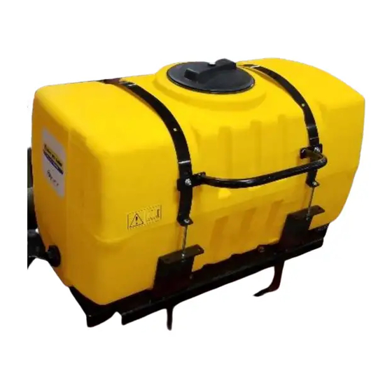
Congratulations on purchasing a Harvest Tec Model 442P/442U/442UP applicator. This applicator is designed to apply Harvest Tec buffered acid. The model 442P/442U/442UP base kit includes the following parts: tank, frame, pump, gauge, hose, electronic control box, and miscellaneous hardware. For your convenience we have included a parts break down for the model 442P/442U/442UP applicator. -
Page 5: Installation Of The 442P Applicator
Installation of 442P Applicator (55-Gallon Applicator System) Tank and Saddle Installation 1. Locate the left saddle leg, 001-4703XPL, and mount to the left side of baler. Locate one leg shim bracket, 001-4703XS, and place in between the leg and side of the baler. Use three 1/2" x 1-1/4”... - Page 6 Tank and Saddle Installation (continued) Installation of Optional Beacon 1. Bolt beacon L-Bracket to beacon support (001-4703XBM) using two 5/16” x 3/4” bolts and 5/16” flange nuts. 2. Secure beacon support to top of right saddle leg (001-4703XPR) at point A using four 3/8” x 1” hex bolts and flange nuts.
-
Page 7: Drain / Fill Kit Installation
Installation of Pump Manifold (442P) Mounting Front Pump Plate Support Baler Mounting Holes 001-4703XJ Drain Fill Kit Mounting Holes A. Mount the Pump Mounting Bracket (001-4703XJ) to the angled support tube with two 5/16” x 1” hex bolts, flats, locks, and nuts. Use the specified mounting holes as shown in the figure above. - Page 8 001-4120S Pump Mounting Plate Holes Installation of Drain / Fill Kit (442P) Locate parts bag 1. Thread 3/4" elbow fitting (003-EL3434) into end of tank. Run 3/4" hose from the elbow down the frame to the bottom of the baler. Locate the two holes on the baler’s angled support bracket that line up with the holes in the valve bracket and attach using two 5/16”...
- Page 9 Installation of Gauge and Hose Manifold (442P) A. Drill two 3/8” holes and mount pressure gauge to sheet metal. Bend the gauge bracket to adjust the angle. B. Secure with two 5/16” x 1” flange bolts and flange nuts.
-
Page 10: Installation Of The 442U / 442Up Applicator
INSTALLATION OF 442U/442UP APPLICATOR (25-Gallon Applicator System) INSTALLATION OF TANK, MOUNTING BRACKETS, GAUGE, & DRAIN/FILL LINE 442U TANK MOUNTING BRACKET Locate the tank base bracket (001-4442U). This bracket will mount on the front of the baler is show below. Depending on the year of the baler only two of the required three holes may be premade on the baler. - Page 11 450 ROLL-BELT UTILITY PLUS TANK MOUNTING (442UP) Place the base bracket (001-4442PU) between the side sheets and fasten with 2x ½”-13 hex bolt, lock washer, flat washer from the outside of the side panel on EACH SIDE, into the weld nuts on the base bracket.
- Page 12 INSTALLATION OF TANK, GAUGE, & DRAIN/FILL LINE CONT. 442U / 442UP Mount the tank on the tank base bracket (001-442U or 001-442UP) as shown below and on the previous page. The position the tank and saddle so that the additional side hole on the tank will be facing the front of the baler.
-
Page 13: Installation Of Spray Nozzle Assembly
INSTALLATION OF SPRAY NOZZLE ASSEMBLY Placement of Spray Nozzle Assembly- 442P Shield 001-4435NCP ate the shield under the frame. B. Position the spray shield support (001- 4435NCP) behind the shield with the formed flange to the rear. C. Attach spray shield support to baler frame with one 3/8”... - Page 14 Placement of Spray Nozzle Assembly- 442U / 442UP The cross bar on the wind guard above the pick-up head provides a mounting point for the nozzle pipes. Space the nozzles by the chart below: PICK-UP HEAD LEFT SIDE CENTER RIGHT SIDE WIDTH (Use plugged fitting) (Use 2-way fitting)
-
Page 15: Installation Of Controls
INSTALLATION OF CONTROLS APPLY RATE DECAL (if not already applied onto control box) Apply the rate decal that came in the bag with this book and place it just to the right of the speed dial. LOCATION OF CONTROL BOX Locate the control in an area that allows operation for adjusting or turning the controls while operating the baler. -
Page 16: Operating Instructions
OPERATING INSTRUCTIONS The 442P/442U/442UP applicator is very simple to operate. After installing the applicator, fill the tank with 5 gallons of water. With control box connected to the applicator and the power cord hooked to the 12-volt battery we can start the test. First flip on the toggle switch. You might hear the buzzing of the motor. -
Page 17: Calibration
CALIBRATION There are three things that you need to know when calibrating your applicator. First you need to know how many tons per hour you bale. Second you need to know the rate, or how many pounds of product to apply for a given ton per hour. Finally you need to know what tips to use and at what pressure to set the gauge. -
Page 18: Determining Rate Of Chemical
To find the exact number of pounds required, for a given hay moisture, refer to the label on the drum or contact the manufacture. Harvest Tec applicators come with low, medium, and high sets of tips. If your chemical requires rates other than what these tips deliver you will need to purchase them through your dealer. - Page 19 GENERAL CALIBRATION CHART IN POUNDS PER HOUR Use the following chart for all applications that require pounds measurements. POUNDS PER HOUR WITH THREE NOZZLES INCLUDED IN KIT YELLOW GREEN BLUE BLACK 650067 XR11001 XR110015 XR11002 XR11004 CENTER 650033 650050 6501 6502 6503 OUTSIDE...
-
Page 20: Routine Maintenance
8. WARNING: Do not climb on baler for maintenance. WINTER STORAGE If Harvest Tec product is being used, winterization is not necessary as long as the tank lid seals tightly and there are no leaks in the system allowing moisture to infiltrate the system. -
Page 21: Troubleshooting Checks
TROUBLESHOOTING CHECKS PROBLEM POSSIBLE CAUSE SOLUTION Pump will not run. 1. Circuit breaker tripped 1. Check for short, low voltage, on electronic unit. and reset breaker. 2. Pump locked up. 2. Clean or rebuild pump if motor is OK. 3. Damaged wire. 3. -
Page 22: Parts Breakdown
Parts Breakdown Tank and Saddle 442P Description Part # Description Part # 50 Gallon tank 030-9203SQ Tank Support 001-4703XPG Tank Strap 001-4402 Leg Shim 001-4703XS Hand Rail 001-6707HRS Beacon Bracket 001-4703XBM Saddle 001-4703X Tank Cap and Gasket 005-9022H Left Tank Leg... -
Page 23: Model 442U/442Up Tank And Saddle
MODEL 442U/442UP TANK AND SADDLE Ref Description Part # Tank 005-9022 Tank saddle 001-4442 Strap 001-4402 Tank mounting bracket 001-4442U Tank mounting bracket- 450 Roll Belt 001-4442PU 005-9022C Lid gasket 005-9022CG Tank fitting 005-9100 Shims 001-4442US MODEL 442U/442UP BASE KIT Ref Description Part # Ref Description... - Page 24 Pump lead 006-4583 Box Plug 006-4581M Box Plug 006-4581 After Serial # 4550 Pre-Serial # 4549 Complete Control Box 030-0457 Parts Breakdown for Drain Fill (Model 442P) Ref Description Part # Ref Description Part # Straight fitting 003-A3434 Male coupler 002-2205G...
-
Page 25: 442U/442Up Nozzle Assembly
442U / 442UP Drain-Fill Kit Ref Description Part # Ref Description Part # Jiffy clip-large 008-9009 Male shut-off 002-2205G Jiffy clip-small 008-9010 Female coupler 002-2204A Ball valve 002-2200 Straight fitting 003-A3434 Valve bracket 001-6702H Elbow fitting 003-EL3434 Hose clamp 003-9004 442U/442UP Nozzle Assembly Description Part#... - Page 26 442P Spray Shield Assembly Description Part # Ref Description Part# Spray Sheild Holder 001-4435NCP Eva Tubing 1/2" 002-9001 Spray Sheild 001-4435NSX Hex Plug 1/4" 003-F14 1/4" x 1/2" Straight Fitting 003-A1412 ¼ NPT Tip Silver* 004-T8001-PT 1/4" x 1/2" 003-A1412F ¼...
- Page 27 442P Installation Base Kit Description Part # Ref Description Part# Pump Bracket 001-4703XJ Elbow 003-EL3812 1/2” Fitting 003-A1212 Harness Pump Lead 26ft 006-4574 Ball Valve 002-2212 Hose Clamp 003-9003 1/2” Nipple 003-M1212 Tee 1/4" 003-TT14 Elbow 1/2” Elbow Fitting 1/4” x 1/2"...
- Page 28 NOTES...
- Page 29 NOTES...
- Page 30 NOTES...
- Page 31 Harvest Tec, LLC. within 30 days of the failure. Parts must be returned through the selling dealer and distributor, transportation charges prepaid.
- Page 32 HARVEST TEC, LLC. P.O. BOX 63 2821 HARVEY STREET HUDSON, WI 54016 PHONE: 715-386-9100 1-800-635-7468 FAX: 715-381-1792 Email: info@harvesttec.com...
Need help?
Do you have a question about the 442P and is the answer not in the manual?
Questions and answers