Table of Contents
Advertisement
Quick Links
Advertisement
Table of Contents

Related Manuals for Diamond Products CC5555GK-3-36


Summary of Contents for Diamond Products CC5555GK-3-36
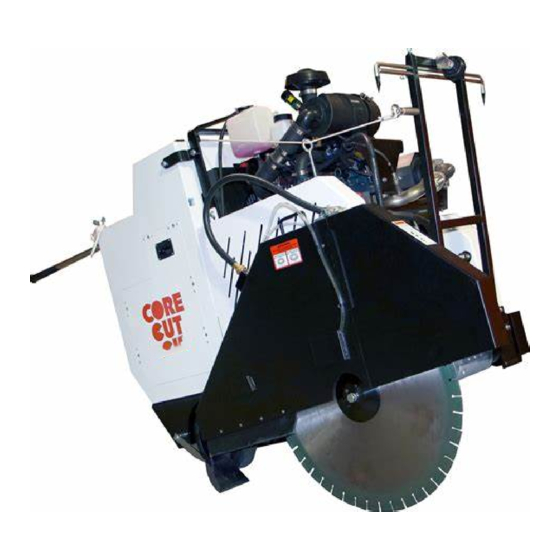
- Page 1 CONCRETE SAW OPERATOR’S MANUAL CC5555GK-3 February 2019 Part #: 1802669...
- Page 2 Select an option below to find your Equipment We sell worldwide for the brands: Genie, Terex, JLG, MultiQuip, Mikasa, Essick, Whiteman, Mayco, Toro Stone, Diamond Products, Generac Magnum, Airman, Haulotte, Barreto, Power Blanket, Nifty Lift, Atlas Copco, Chicago Pneumatic, Allmand, Miller Curber, Skyjack, Lull,...
-
Page 3: Table Of Contents
TABLE OF CONTENTS Introduction ................................. 7 CC5555GK-3 Controls ............................8 CC5555GK-3 Dimensions ..........................9 CC5555GK-3 Specifications ........................... 10 Safety ................................. 11 Safety Alerts ..............................11 Proposition 65 ..............................11 Spark Arrester Requirement ........................... 11 Respiratory Hazards ............................11 General Safety ..............................12 Battery and Electrical Safety ........................... - Page 4 TABLE OF CONTENTS Inspecting the Blade ............................ 27 Blade Speed ..............................28 Installing the Blade ............................28 Removing the Outer Blade Flange ......................28 Removing the Blade ............................ 29 Blade Guard ..............................30 Installing the Blade Guard ........................... 30 Removing the Blade Guard ......................... 30 Flange Guard ..............................
- Page 5 TABLE OF CONTENTS Engine ................................37 Post Cleaning ..............................37 Service Schedule ............................38 Daily Service ..............................39 Check Engine Oil Level ..........................39 Check Fuel Level ............................39 Hydraulic System ............................40 Adding Hydraulic Fluid ..........................40 Check Radiator Coolant Level ........................40 Check Air Cleaner Element .........................
- Page 6 TABLE OF CONTENTS Belt Tension Setting ............................ 51 Testing the Belt Tension ..........................51 Adjusting the Blade Drive Belts ........................52 Replacing the Blade Drive Belts ........................53 Primary Transmission V-Belt ........................... 55 Replacing the Primary Transmission V-Belt ....................55 Secondary Transmission V-Belt ........................
-
Page 7: Introduction
Equipment modifications should be made by Diamond Products to ensure safety and design. Any modifications made by the owner(s) are not the responsibility of Diamond Products and void all equipment warranties if a problem arises as a result of the modification. -
Page 8: Cc5555Gk-3 Controls
INTRODUCTION CC5555GK-3 Controls CC5555GK-3 Controls 1. Ignition Switch – Starts the engine and 10. Fuse/Switch Panel Cover – Allow access to provides power to certain components. fuse block assembly. 2. Engine Throttle Switch – Increases and 11. Handlebar Lock Knob – Locks the handlebar decreases engine/blade speed (RPM). -
Page 9: Cc5555Gk-3 Dimensions
INTRODUCTION CC5555GK-3 Dimensions CC5555GK-3 Dimensions Inches Millimeters A Saw Height 1245 B Saw Length – Minimum 1295 C Saw Length – Maximum 2819 D Handle Extension – Maximum Frame Length 1118 Wheel Base Length 18-1/2 G Saw Width H Frame Width (Front) Frame Width (Rear) 25-1/2 Front Wheels Inside Width... -
Page 10: Cc5555Gk-3 Specifications
INTRODUCTION CC5555GK-3 Specifications Saw Specifications Maximum Cutting Depth 14-3/4” with 36” blade Blade Shaft Diameter 2” Arbor Diameter 1” with driven pin Blade Shaft Bearings Oil Filled Blade Shaft Drive 7 V-Belts Blade Mounting Right or left Blade Raise/Lower Electro-hydraulic pump Blade Coolant Dual water tubes Blade Guard Attachment... -
Page 11: Safety
4442, maintained in effective, working order or the engine is constructed, equipped, Refer to the Diamond Products Parts List for and maintained for the prevention of fire additional information and part diagrams. Refer to pursuant to section 4443. -
Page 12: General Safety
SAFETY PRECAUTIONS DO NOT: General Safety Assume the equipment will remain still when in Read and understand all safety, operations, • • neutral or when parking/stopping the equipment and maintenance instructions provided in this on a slope. Chock the wheels to help prevent manual prior to operating or servicing the saw. -
Page 13: Battery And Electrical Safety
SAFETY PRECAUTIONS DO NOT expose yourself or anyone Battery and Electrical Safety • else to the direct line of the blade Ignitable explosive gases when operating the equipment. • emitted from the battery. DO NOT Always use an appropriate size blade and the expose the battery to sparks or open •... -
Page 14: Fuel Safety
SAFETY PRECAUTIONS Always pivot the front of the blade Make sure the equipment is in neutral when • • guard 180° (fully upward) so the starting the engine. guard does not swing down Fill the fuel tank and check the oil level prior to •... -
Page 15: Hydraulic Safety
SAFETY PRECAUTIONS DO NOT allow any person, animal, and/or Transporting Safety • objects in and around the work area while Remove the blade prior to transporting the cutting. • equipment. DO NOT install a blade on the machine until it •... -
Page 16: Display Panel Controller
Turning the ignition switch to run or start will activate a sequence of screens on the display panel. First, you will see the Diamond Products logo and then the main gauge screen which is considered the home screen. If one or more of the emergency stop triggers are activated, E-stop switch is active, or coolant level is low, an emergency shutdown window will be displayed. -
Page 17: Soft Keys (Buttons)
DISPLAY PANEL CONTROLLER Soft Keys (Buttons) The Soft Key choices provide different selection options. These will appear on the bottom of the display screen and can be selected by pushing the button directly below the soft key. Soft Key Description Freeze Frame –... -
Page 18: Status Icons
DISPLAY PANEL CONTROLLER Status Icons The Status Icons are color coded and light up when communicating to the operator. Pay close attention to any Status Icons and color if they appear. Status Icon Description Check Engine – Yellow icon is visible if the controller receives a DM1 (Active Diagnostic Trouble Code) message with an amber lamp command. -
Page 19: Main Gauge Screen
DISPLAY PANEL CONTROLLER Main Gauge Screen Dial Gauges The Main Gauge Screen is the default (Home) The three dial gauges on the home screen are as screen when the saw is turned on. There are follows: three soft key options available from the Home Engine/Tachometer Speed –... -
Page 20: Digital Gauges
DISPLAY PANEL CONTROLLER Gauges (Main Menu default screen) Digital Gauges Diagnostics The six digital gauges on the home screen User Settings provide the following input: Panel Configuration (Password Required) Service (Password Required) Oil Pressure – This gauge indicates the • System Information engine oil pressure in PSI. -
Page 21: Gauges
DISPLAY PANEL CONTROLLER Press the UP/DOWN soft keys to reach the next Gauges diagnostic in the list. Returns screen to Main Menu Diagnostics The screen displays the following items: Active Diagnostics • Logged Diagnostics • Active Diagnostics Screen Logged Diagnostics Use the UP/DOWN soft keys, and stop the cursor next to the action item Logged Diagnostics. -
Page 22: User Settings
DISPLAY PANEL CONTROLLER Screen Color Using the UP/DOWN soft keys stop the cursor next to the action item, Colors. Set your preference for day or night vision by using the +/– soft keys. To exit the screen select the Main Menu ) soft key and then the Select ( ) soft key. - Page 23 DISPLAY PANEL CONTROLLER Units Using the UP/DOWN soft keys stop the cursor next to the action item, Units. Set your unit preference using the +/– soft keys. To exit the screen select the Main Menu ( ) soft key and then the Select ( ) soft key.
-
Page 24: System Information
DISPLAY PANEL CONTROLLER System Information Blade Depth Stop Setting Scroll through the Menu list using the UP/DOWN 1. Lower the saw until the blade touches the cutting surface. soft keys, and stop the cursor next to the action 2. Press the “Zero Blade / Clear Zero” soft key item System Info. -
Page 25: Reset New Blade Depth Stop Setting
DISPLAY PANEL CONTROLLER Reset New Blade Depth Stop Setting Clear All Blade Depth Stop Settings 1. To clear the depth setting and reset to a new To clear all of the blade depth settings: setting, press the “Clear Depth Stop” soft key. 1. -
Page 26: Operating The Cc5555Gk-3
OPERATING front side of the blade. Holding the string ends Operating the CC5555GK-3 in one hand, tension the lines out toward the front pointer rod. Handlebars The handlebars help the operator guide and maneuver the saw. Adjusting the Handlebars 1. Loosen both handle lock knobs. 2. -
Page 27: Rear Pointers
OPERATING Rear Pointers Diamond Blades The rear pointer rods act as guides when cutting. WARNING Adjusting the Rear Pointers DO NOT exceed the blade’s maximum recommended speed when cutting. Excessive blade speeds can cause blade breakage, resulting in serious injuries and/or death. Using the proper blade (size and type) preserves the blade and improves cutting and operator efficiency, resulting in lower costs. -
Page 28: Blade Speed
Contact technical support prior to running the saw. Refer to the RPM & Gear Position chart posted on the saw, or in the Diamond Products’ Parts List for additional information. Removing the Outer Blade Flange CC5555GK-3 RPM Chart... -
Page 29: Removing The Blade
OPERATING Place the wedge lock washer onto the blade shaft bolt and insert the bolt into the blade shaft. 10. Tighten the bolt by hand as much as possible, and slowly lower the blade until it just touches the ground’s surface. 11. -
Page 30: Blade Guard
OPERATING 6. Align and fit the outer flange alignment pin and 3. Connect one end of the water supply hose to shaft into the blade shaft and inner flange the gearbox and the other end to the blade alignment pin hole. guard hose fitting. - Page 31 Select an option below to find your Equipment We sell worldwide for the brands: Genie, Terex, JLG, MultiQuip, Mikasa, Essick, Whiteman, Mayco, Toro Stone, Diamond Products, Generac Magnum, Airman, Haulotte, Barreto, Power Blanket, Nifty Lift, Atlas Copco, Chicago Pneumatic, Allmand, Miller Curber, Skyjack, Lull,...
-
Page 32: Flange Guard
OPERATING Flange Guard Installing the Flange Guard 1. Place the square mount of the flange guard down onto the blade guard mount on the frame base and slide down until fully seated on the frame base. Water Supply Connection Connect the water supply hose from the gearbox to the blade guard hose fitting. -
Page 33: Water Pump
OPERATING Water Pump Lowering Speed The lowering speed metering valve changes the The water pump (optional item) directs water from saw’s lowering speed. The valve is located inside the water source hose to the saw blade. the upright compartment on the right side of the 1. -
Page 34: Forward Control
OPERATING You will need to rotate the output shaft BY Forward Control HAND to complete this motion. Push the speed control lever forward to the desired traveling speed. The maximum speed the saw will move forward, at full throttle, is 250 ft. /min. Reverse Control Pull the speed control lever backward to the desired traveling speed. -
Page 35: Unleaded Fuel
OPERATING Ignition Switch Fuel Tank Cap 4. Remove the fuel tank cap. 5. Fill the fuel tank with unleaded fuel only. Refer to the engine manual for a list of appropriate Ignition Switch fuels. STOP - turns off the engine. 6. -
Page 36: Starting The Engine
5 minutes. panel. First you will see the Diamond Products Turn the key to Stop and remove the key. logo display and then the main gauge screen is displayed. -
Page 37: Tasks Prior To Cutting
OPERATING Push the speed control lever forward to reach Tasks Prior to Cutting the desired traveling speed for maximum Complete the following tasks prior to cutting: efficiency. Raise and lower the blade as necessary, paying attention to the cutting depth Raise the blade to provide proper clearance indicator. -
Page 38: Maintenance
MAINTENANCE that the saw is cool prior to cleaning. Ensure Maintenance affected electrical equipment is properly covered or de-energized prior to cleaning with General water or air. Failure to read and comply with the Cleaning Techniques maintenance instructions provided in this manual prior to performing maintenance may Various cleaning options can be utilized result in serious injuries and/or death, and may... -
Page 39: Service Schedule
MAINTENANCE Service Schedule The service schedule is based primarily on the standard operating time of the machine. The frequency of the maintenance tasks can be increased based on the working environments of the machine. 1000 Daily Hrs. Hrs. Hrs. Hrs. Hrs. - Page 40 MAINTENANCE Daily Service Check Fuel Level Prior to checking the fuel level, ensure that there is Check Engine Oil Level no blade installed on the saw and that the saw Prior to checking the engine oil level, ensure that frame is in a level position. there is no blade installed on the saw and that the 1.
-
Page 41: Hydraulic System
MAINTENANCE Hydraulic System WARNING Turn the engine off prior to performing maintenance on the hydraulic system. Lower the saw to the floor so it is level to release the pressurized hydraulic fluid in the hydraulic system prior to performing maintenance on the hydraulic system. Always place a piece of cardboard or paper up against hydraulic components, or use a leak detection fluid to check for hydraulic fluid... -
Page 42: Check Air Cleaner Element
MAINTENANCE Draining the Gearbox Heat Exchanger – Freezing Temps To avoid water freezing in heat exchanger and potentially causing housing cracks it is necessary to drain the Heat Exchanger daily or when not in use for extended periods, in freezing ambient temperatures. -
Page 43: Draining The Optional Water Pump - Freezing Temps
MAINTENANCE Water Valve - ON From the fuse/switch panel cover plate, turn the water pump to the ON position. Water Supply to 3-Speed Gearbox CAUTION 3. Disconnect the hose from the outlet of the water Do not allow the pump to operate dry for more valve. -
Page 44: Clean The Air Cleaner Element
MAINTENANCE 100 Hour Service Clean the Air Cleaner Element WARNING DO NOT operate the saw without the filter installed Service the outer primary filter according to the restriction indicator service bar. Replace the filter annually. DO NOT over-service or under-service the filter. -
Page 45: Changing Oil - Three Speed Gearbox
MAINTENANCE 7. Remove the oil filter located on the front of the engine using a filter wrench. 8. Dispose of the oil and filter in accordance with city, state and federal regulations. 9. Shut oil drain valve and replace red plastic drain plug. -
Page 46: Replacing The In-Line Fuel Filter
MAINTENANCE 10. Open the fuel shutoff valve. 500 Hour Service 11. Reinstall the right side access panel onto the Replacing the In-Line Fuel Filter upright assembly. Replace the in-line fuel filter every 500 hours or 12. Dispose of the used fuel and filter according to yearly depending on the amount of sediment in the city, state, and federal regulations. -
Page 47: 1000 Hour Service
MAINTENANCE CAUTION Remove the radiator cap only when it feels cool to the touch, and always open it slowly to relieve any built up pressure. 2. Slowly remove the radiator cap. 3. Attach a hose with a 1/4” male thread fitting onto the petcock drain vale located on the lower front end of the radiator. -
Page 48: Handlebars
MAINTENANCE 3. Place the inner flange onto the indented portion Handlebars of the blade shaft. The handlebars generally require little or no 4. Apply Loctite 262 (red) or an equivalent to the maintenance and, when used correctly, should setscrew threads. remain in good condition. -
Page 49: Battery
MAINTENANCE 4. Remove the positive battery boot and Battery disconnect the positive battery cable lead from the positive battery terminal. WARNING 5. Pull the battery up off the battery platform, Ignitable explosive gases are emitted keeping it level. from the battery. DO NOT expose the 6. -
Page 50: Circuit Breakers And Terminal Blocks
MAINTENANCE operating the saw, the magnetic sensor needs to Circuit Breakers and Terminal Blocks be adjusted or replaced. There are two 50 amp circuit breakers associated with the CC5555GK-3. The first 50 amp breaker, for the cooling fan, is located inside the upright compartment on the right side of the saw. -
Page 51: Speed Control Lever
MAINTENANCE Speed Control Lever When the speed control lever is out of sync with the saw’s movement; for example, if the saw moves forward when the lever is at Neutral adjustments are needed. Adjusting the Speed Control Lever With saw running, move the speed control lever forward or reverse until the saw does not move. -
Page 52: Optional Water Pump
Testing the Belt Tension Belt System Test the blade drive belt tension on a daily basis using a sonic tension meter sensor (can be ordered through Diamond Products), in accordance with WARNING manufacturers specifications. Turn the engine off prior to performing belt maintenance. -
Page 53: Adjusting The Blade Drive Belts
MAINTENANCE Adjusting the Blade Drive Belts Inspect the belts for fraying, stress cracks, and/or breakage and replace immediately if there are damages. Test the belt tension. Proceed to step 3 if the belts need tensioning. Operate the saw as needed if no tension adjustments are required. Locate the PTO belt guard on the left side of the saw. -
Page 54: Replacing The Blade Drive Belts
MAINTENANCE Front Blade Shaft Assembly Bolt - Left Side Turnbuckle Tensioning Assembly Once the blade drive belts are tightened properly, tighten the jam nut on the turnbuckle tensioning assembly. Tighten the four hex head bolts that attach the blade shaft assembly to the frame. Replace the PTO and alternator belt guards. - Page 55 MAINTENANCE 3. Locate the four bolts that attach the blade shaft assembly to the frame base. Loosen the bolts using a 3/4" wrench to allow for free rotational movement of the blade shaft assembly. DO NOT remove these bolts. PTO Belt Guard Bolts – Front (3) 2.
-
Page 56: Primary Transmission V-Belt
MAINTENANCE Replacing the Primary Transmission V-Belt 1. Remove the tension from the rotary tensioner. 2. Remove the blade drive belts from the PTO sheave. 3. Remove the V-belt from the rotary tensioner idler pulley, the front transmission jackshaft pulley, and the PTO sheave. 4. -
Page 57: Rotary Tensioner
MAINTENANCE 3. Press and hold the lower right soft key button of Rotary Tensioner the display panel for approximately 10 seconds Adjusting the Rotary Tensioner until the digital “Blade Depth” gauge indicates 0.00 in. 1. Remove PTO belt guard 4. Turn the ignition switch to the OFF position. 2. -
Page 58: Model And Serial Numbers
REFERENCES Appendix A Model and Serial Numbers Record the saw’s serial number below for future reference and customer service purposes. Serial Number Record the engine’s model and serial numbers below for future reference and customer service purposes. Model Number Serial Number... -
Page 59: Troubleshooting
REFERENCES Appendix B Troubleshooting Table 1: Troubleshooting Symptom Problem Solution Emergency stop button Pull up on emergency stop button. activated? Out of fuel? Check for fuel in tank. Fuel filter or fuel lines clogged? Replace fuel filter or fuel lines. Air in fuel lines? Bleed fuel lines. - Page 60 REFERENCES Table 5: Troubleshooting (cont.) Symptom Problem Solution Misaligned rear axle? Adjust rear axle alignment. Excessive force applied while Reduce forward speed. sawing? Blade does not cut straight. Contact Discount-equipment. Wrong blade for application? Check belt tension on a regular Loose belts causing slippage? basis.
-
Page 61: Additional Resources
CC5555GK-3 Concrete Saw Parts List, Ohio 2018 • A Guide for Professional Concrete Cutters • Training Manual – Introduction to Diamond Blades, Bits, and Equipment • Diamond Products’ Equipment Catalog • Discount-equipment’ Website (www.discount-equipment.com) • Kubota (www.kubotaengine.com) Operator’s Manual, Kubota SI Engine WG1605-G-E3, Code No. EG523-8916-6. - Page 62 EQUIPMENT AND PARTS WARRANTY Discount-equipment warrants all equipment sold by it against defects in workmanship or materials for a period of one (1) year from the date of shipment to Customer. The responsibility of Discount-equipment under this Warranty is limited to replacement or repair of defective parts, of such parts as shall appear to us upon inspection at such parts, to have been defective in material or workmanship, with expense for transportation and labor borne by Customer.
- Page 63 Select an option below to find your Equipment We sell worldwide for the brands: Genie, Terex, JLG, MultiQuip, Mikasa, Essick, Whiteman, Mayco, Toro Stone, Diamond Products, Generac Magnum, Airman, Haulotte, Barreto, Power Blanket, Nifty Lift, Atlas Copco, Chicago Pneumatic, Allmand, Miller Curber, Skyjack, Lull,...
Need help?
Do you have a question about the CC5555GK-3-36 and is the answer not in the manual?
Questions and answers