Sign In
Upload
Download
Table of Contents
Contents
Add to my manuals
Delete from my manuals
Share
URL of this page:
HTML Link:
Bookmark this page
Add
Manual will be automatically added to "My Manuals"
Print this page
×
Bookmark added
×
Added to my manuals
Manuals
Brands
ZKTeco Manuals
Turnstiles
TS2000 Series
User manual
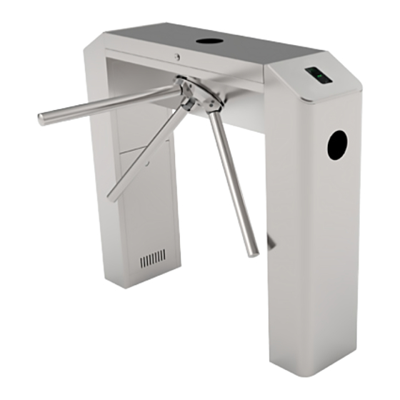
ZKTeco TS2000 Series User Manual
Tripod turnstile
Hide thumbs
1
2
3
4
5
6
7
8
9
10
11
12
13
Table Of Contents
14
page
of
14
Go
/
14
Contents
Table of Contents
Troubleshooting
Bookmarks
Table of Contents
Technical Specifications
Equipment Installation
Cable Diagram
Equipment Precautions and Maintenance
Troubleshooting
Attachment 1 Default Factory Settings
Attachment 2 Connection Diagram of Control Board and Access Control Panel
Advertisement
Quick Links
Download this manual
TS2000 Series Tripod Turnstile User Manual
Version: 2.4
Date: Jan, 2018
Table of
Contents
Previous
Page
Next
Page
1
2
3
4
5
Advertisement
Table of Contents
Need help?
Do you have a question about the TS2000 Series and is the answer not in the manual?
Ask a question
Questions and answers
Related Manuals for ZKTeco TS2000 Series
Turnstiles ZKTeco TS2200 Series User Manual
Vertical tripod turnstile (11 pages)
Turnstiles ZKTeco TS2211 User Manual
Vertical tripod turnstile (11 pages)
Turnstiles ZKTeco TS2222 User Manual
Vertical tripod turnstile (11 pages)
Turnstiles ZKTeco TS1000 Pro User Manual
Tripod turnstile (16 pages)
Turnstiles ZKTeco TS2000PRO Series User Manual
Tripod turnstile (18 pages)
Turnstiles ZKTeco TS2000 Pro Series User Manual
Tripod turnstile (18 pages)
Turnstiles ZKTeco TS1000 Pro Series Installation Manual
Tripod turnstile (8 pages)
Turnstiles ZKTeco TS 1000 Pro Series Installation Manual
Tripod turnstile (7 pages)
Turnstiles ZKTeco TS 1000 Pro Series Installation Manual
Tripod turnstile (8 pages)
Turnstiles ZKTeco TS1000D User Manual
Tripod turnstile (14 pages)
Turnstiles ZKTeco TS2011 User Manual
Tripod turnstile (14 pages)
Turnstiles ZKTeco TS2022 User Manual
Tripod turnstile (14 pages)
Turnstiles ZKTeco TS2000 Plus Series Installation Manual
(14 pages)
Turnstiles ZKTeco TS2000 Plus User Manual
(30 pages)
Turnstiles ZKTeco TS2200 Pro Series Installation Manual
Tripod turnstile (15 pages)
Turnstiles ZKTeco TS1000 Series User Manual
Vertical tripod turnstile (13 pages)
This manual is also suitable for:
Ts2000
Ts2011
Ts2022
Table of Contents
Print
Rename the bookmark
Delete bookmark?
Delete from my manuals?
Login
Sign In
OR
Sign in with Facebook
Sign in with Google
Upload manual
Upload from disk
Upload from URL


Need help?
Do you have a question about the TS2000 Series and is the answer not in the manual?
Questions and answers